Introduction
Today, we are going to tear down a wireless phone charger launched by Tesla. The charging module is suitable for Model S, produced from 2012 to 2020, and Model X, produced from 2015 to 2020. It can provide 7.5W charging power and is powered by a USB-A port. Next, let's take it apart to see its internal components and structure.
Product Appearance
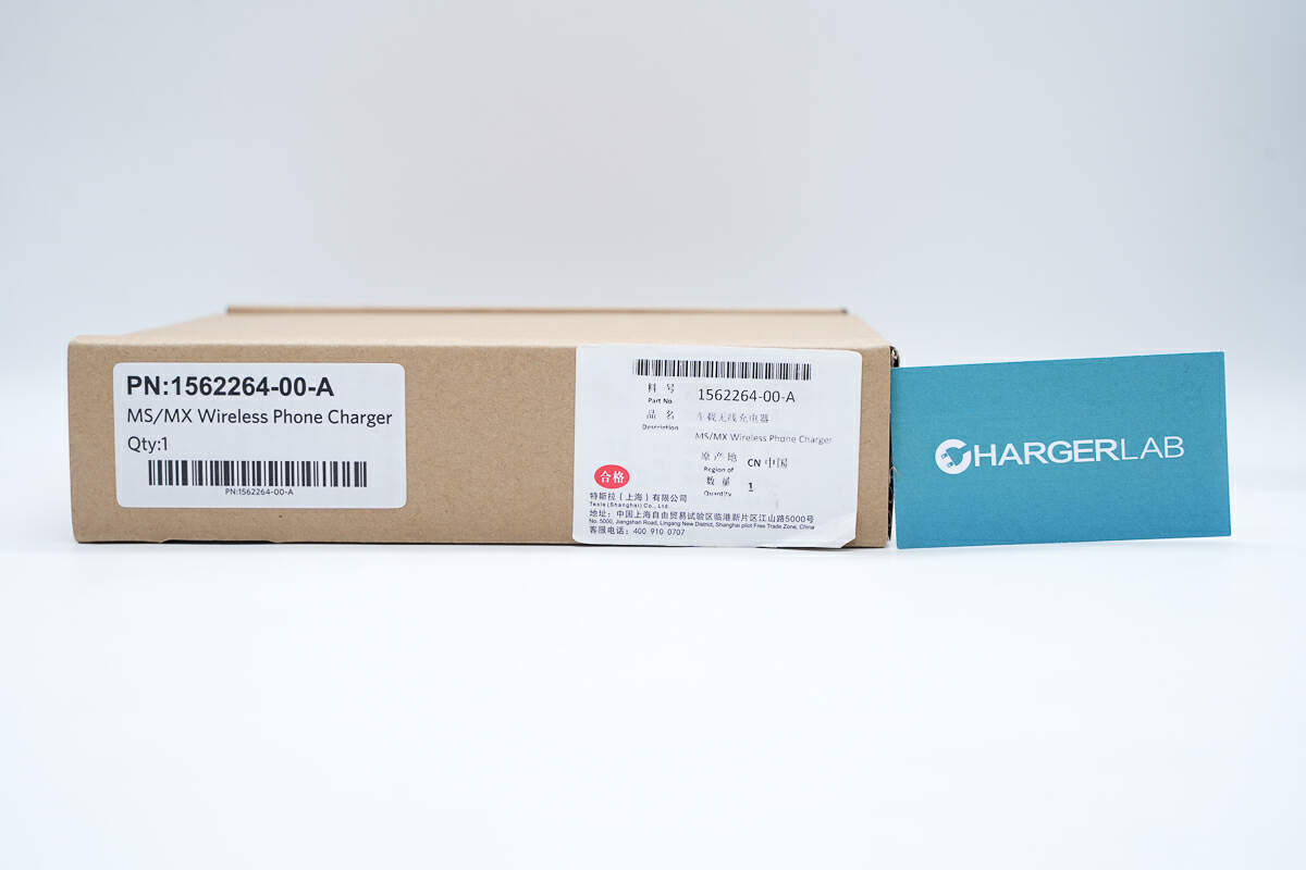
The Tesla Wireless Phone Charger comes in a cardboard box.
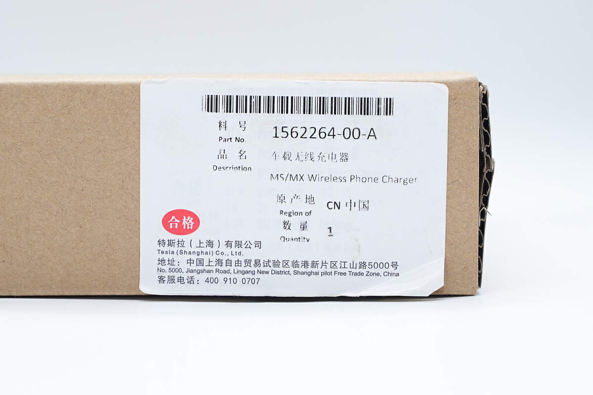
There is a label on the lower right corner of the box.
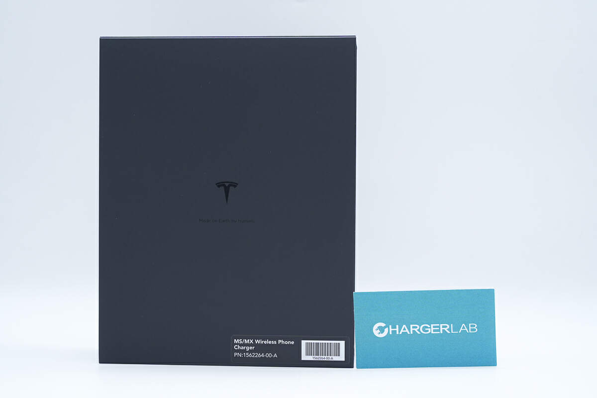
Inside the carton is a black packaging box.

"Made on Earth by humans" is printed below the Tesla logo.
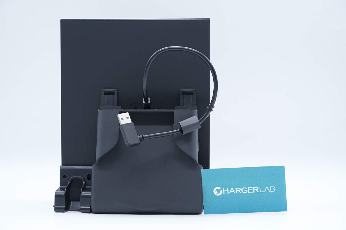
The box contains the wireless phone charger and a fixed bracket.
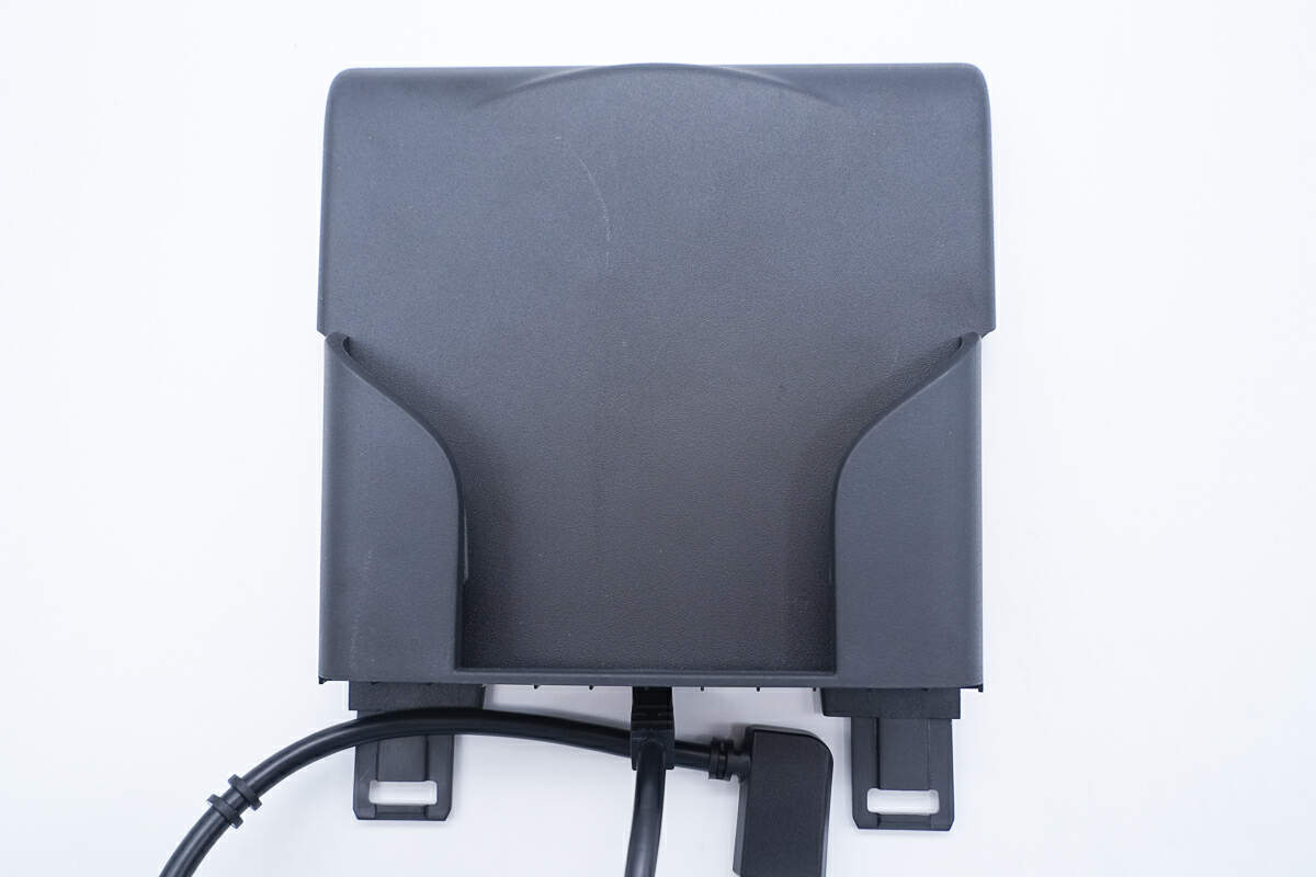
Its front is used to place the phone for wireless charging and also serves as a fixation.
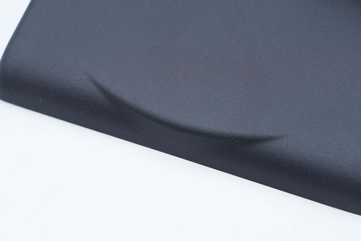
The bump indicates the location of the coil.
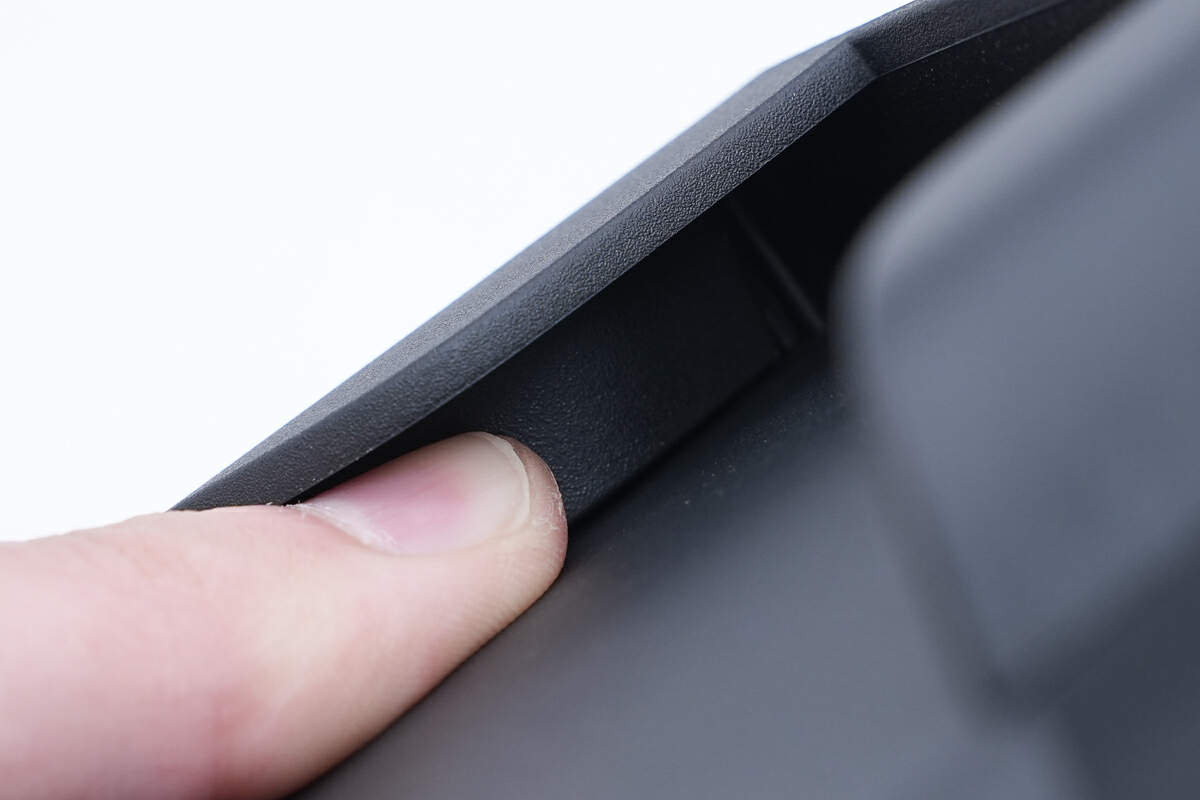
The shells on both sides of the panel are used to fix the phone.
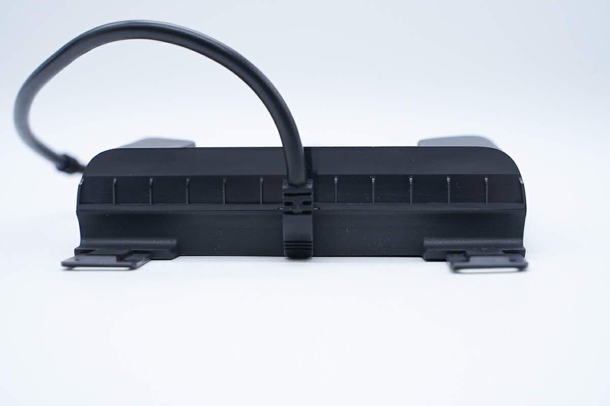
There is a power cord at the bottom.
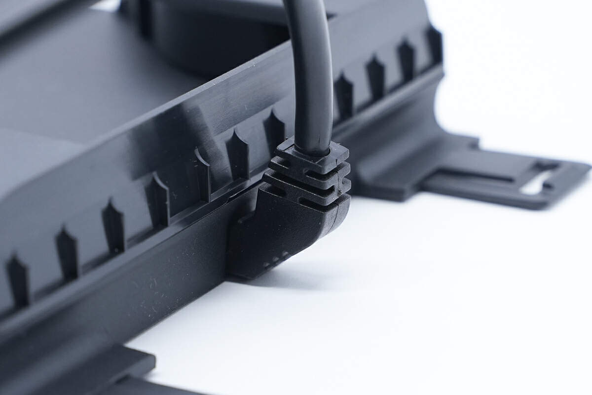
The connection is protected by a sheath.
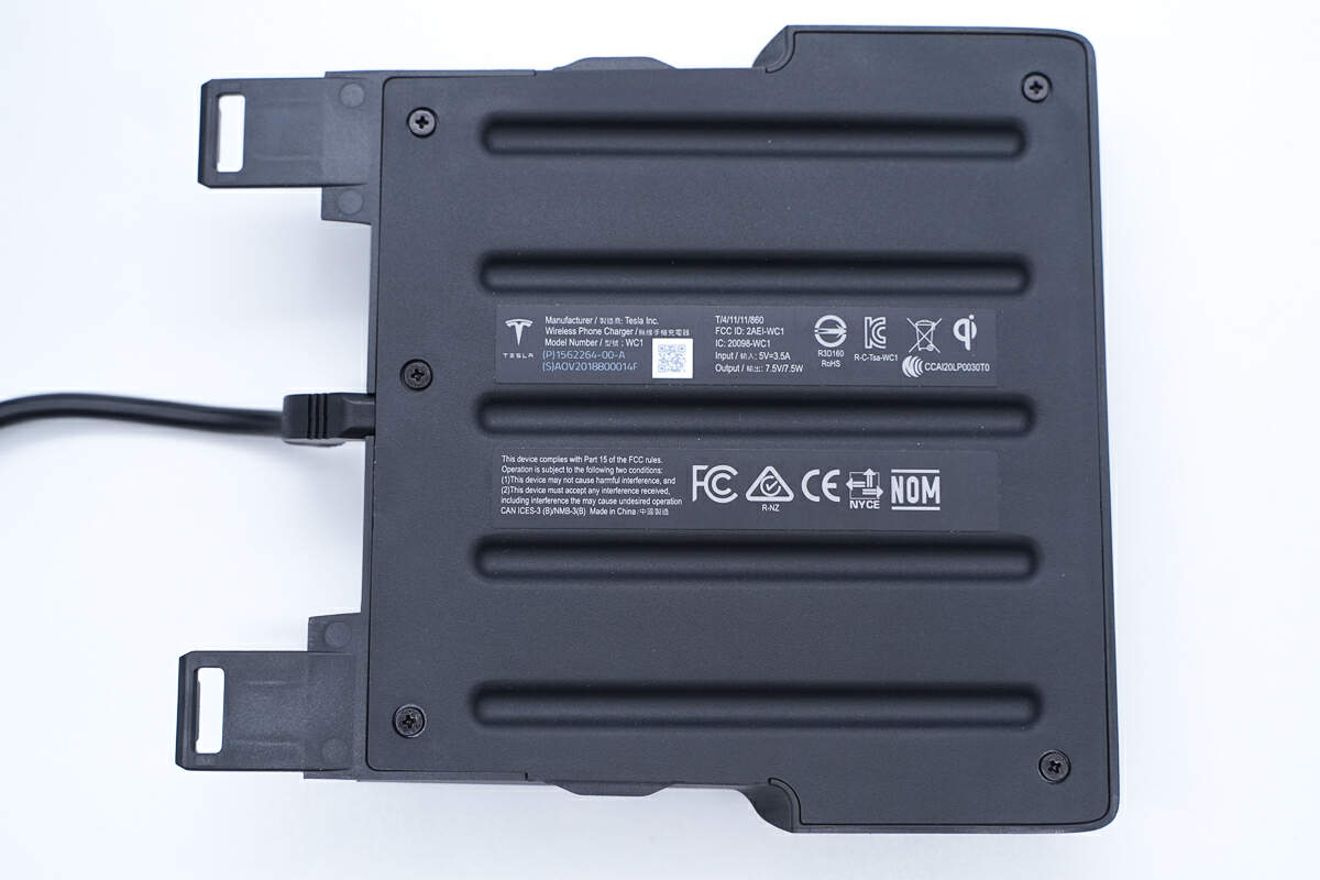
The back cover is fixed by screws, and an information label is attached to it.
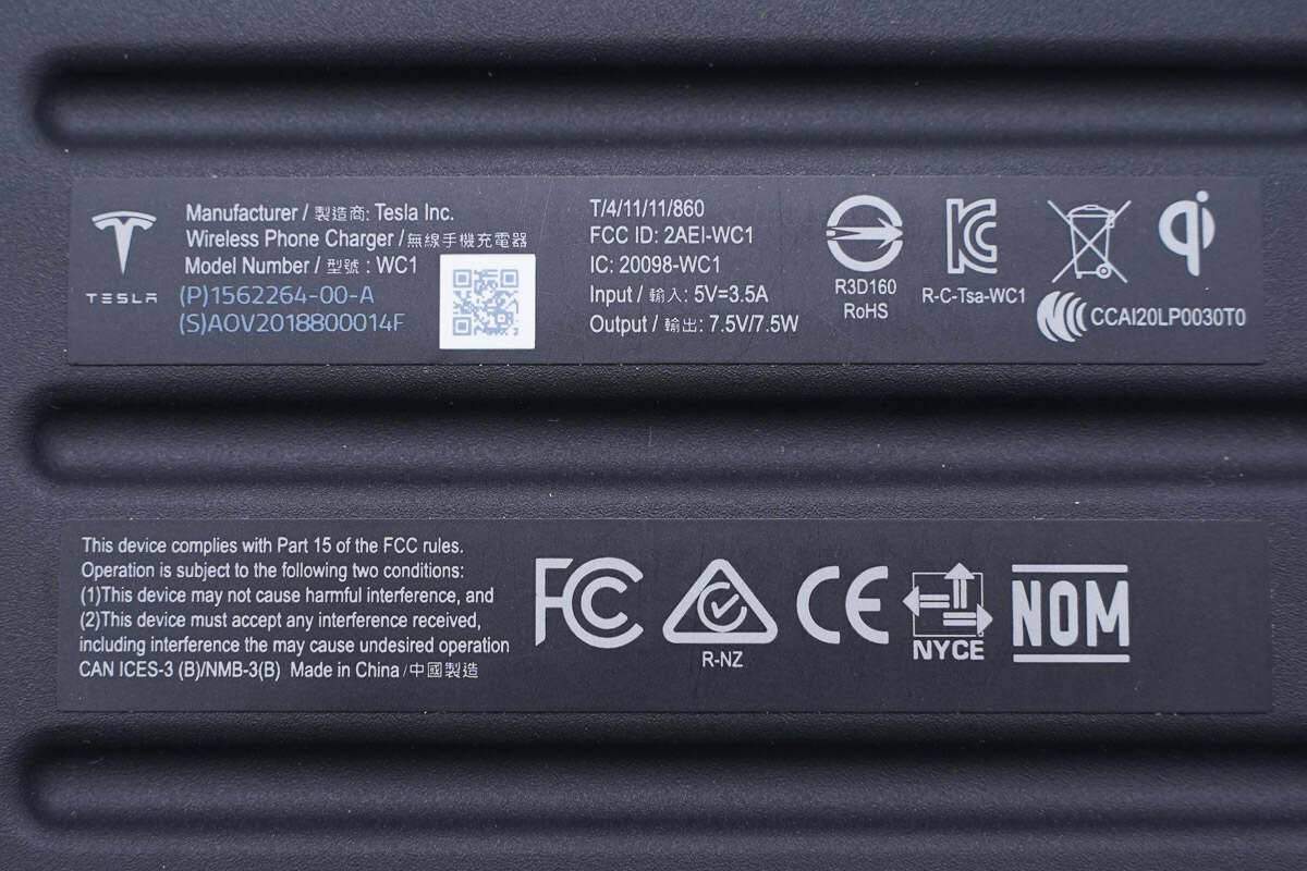
Model is WC1. It can support input of 5V 3.5A. The output is 7.5V/7.5W.
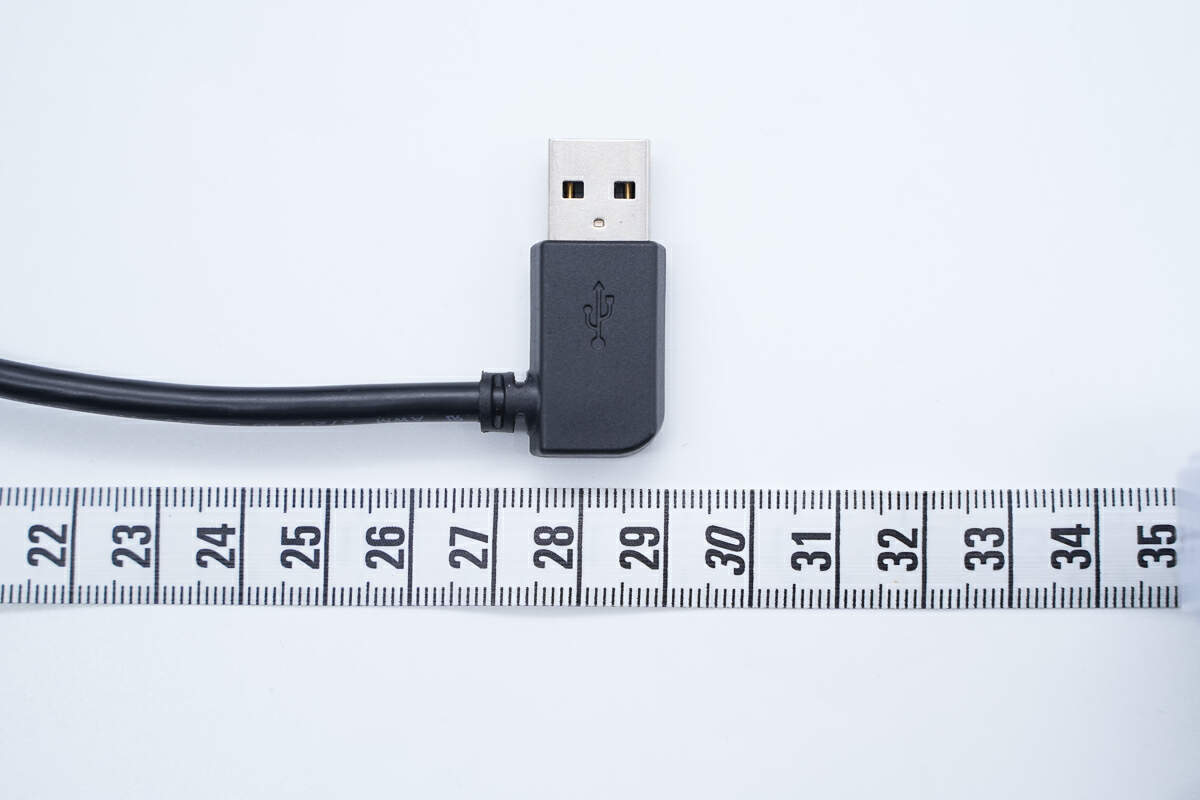
The length of the cable is about 29 cm (11.42 inches).
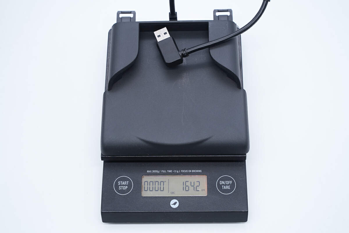
The weight is about 164 g (5.78 oz).
Teardown
Next, let's take it apart to see its internal components and structure.
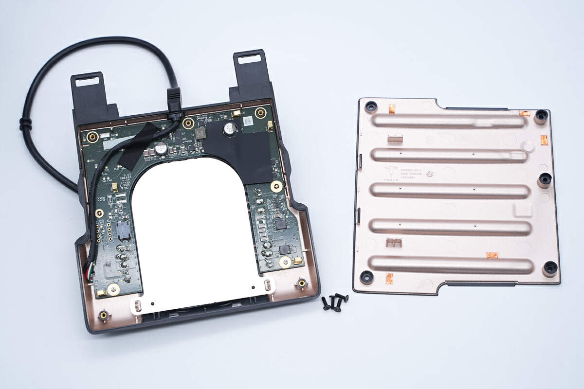
Remove the screws and disassemble the cover.
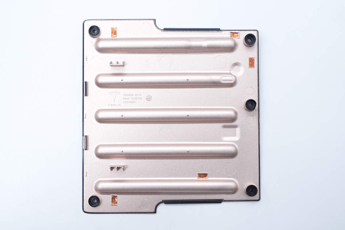
The inside of the back cover is metalized to provide shielding.
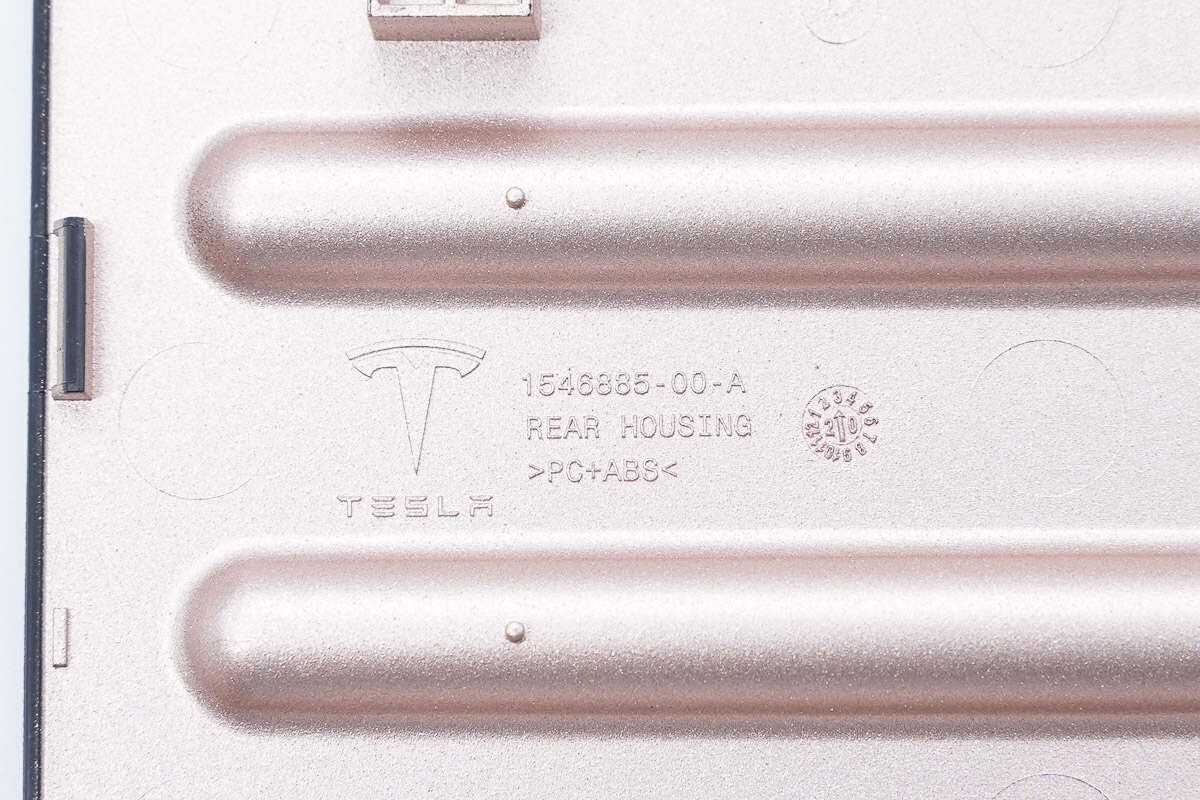
It is printed with the Tesla logo, made of PC+ABS material, and produced in March 2020.
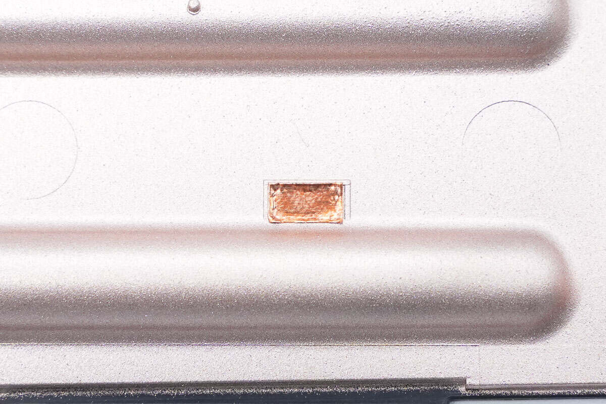
The conductive copper foil is pasted at the position corresponding to the PCB contact point.
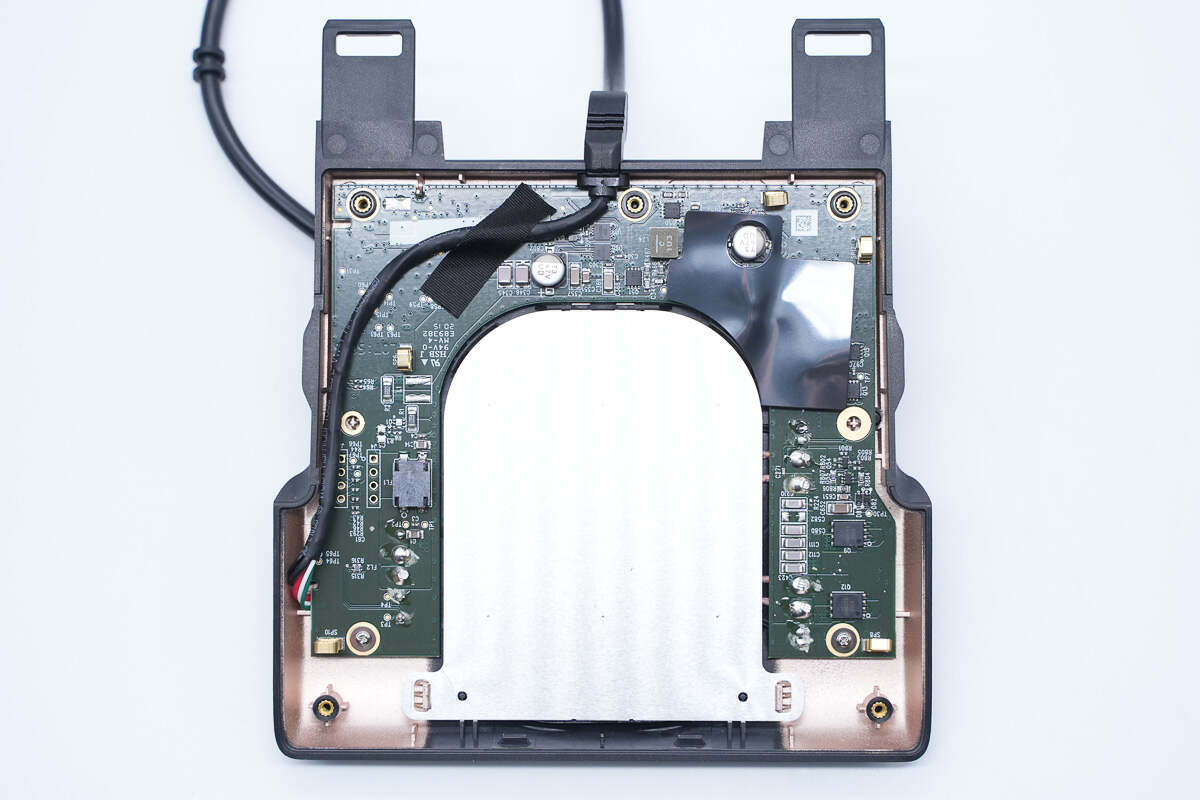
Screws and positioning columns fix the PCBA module, and springs are welded to the corresponding positions of the conductive copper foil for grounding.
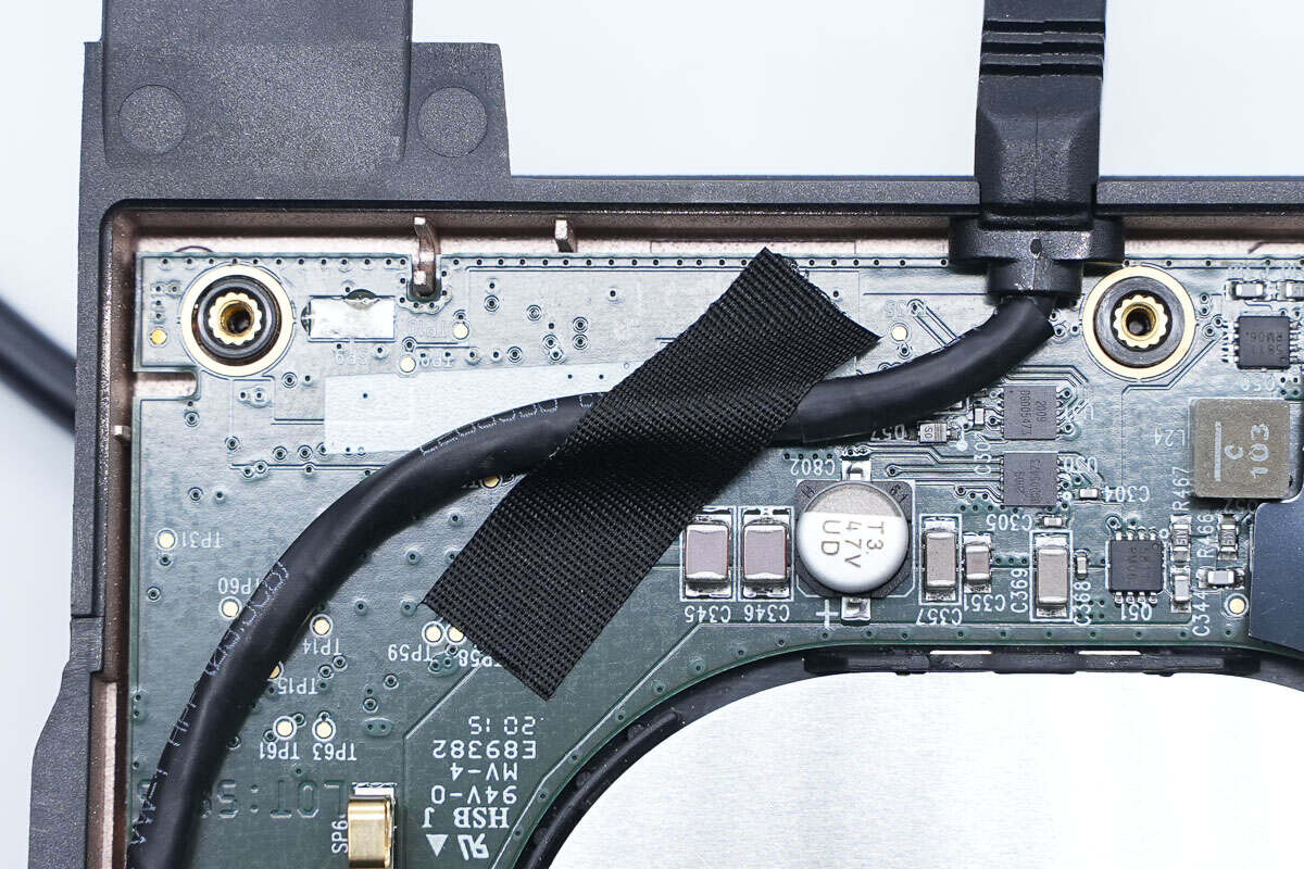
The input cable is fixed with tape.
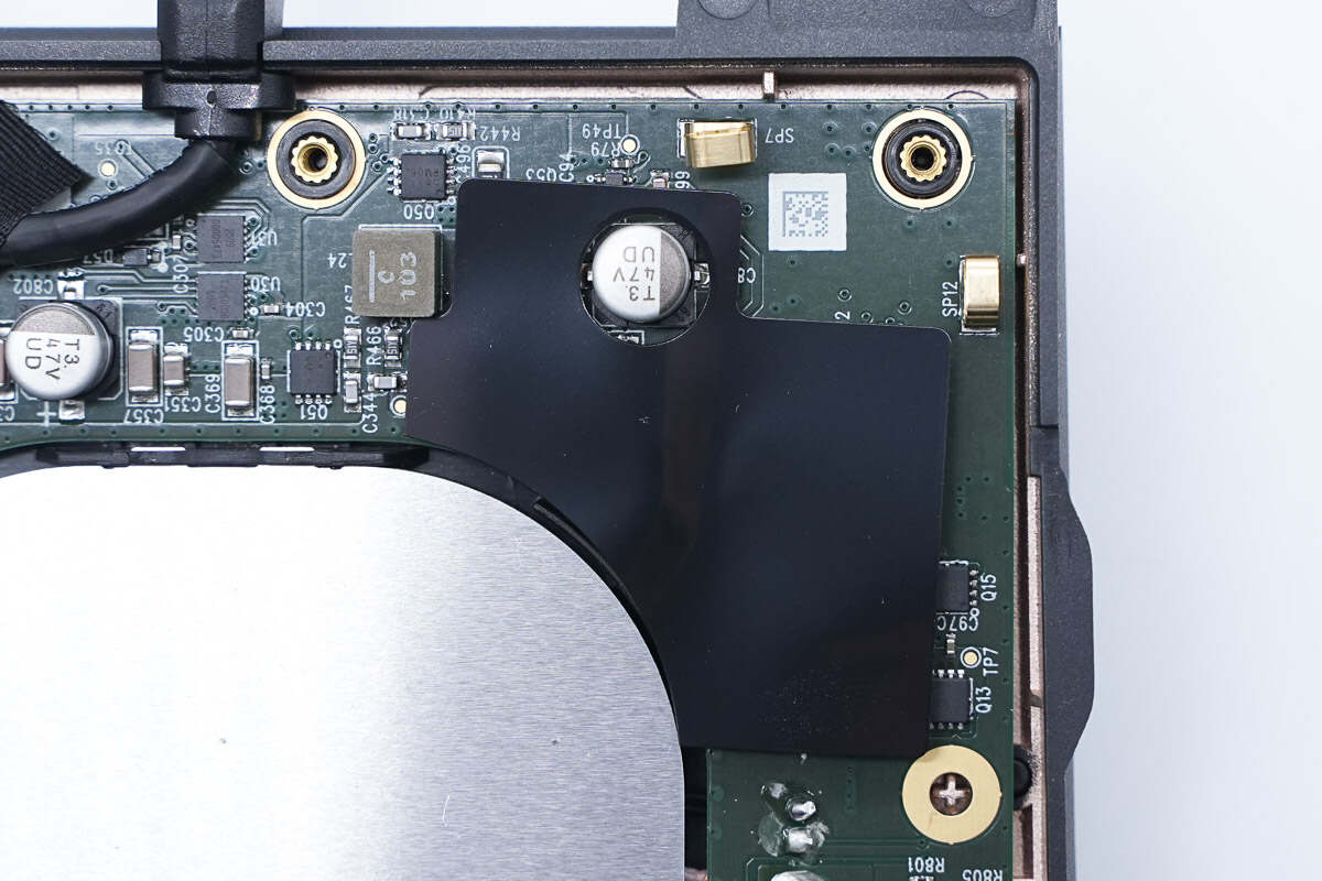
This is the plastic sheet for insulation.
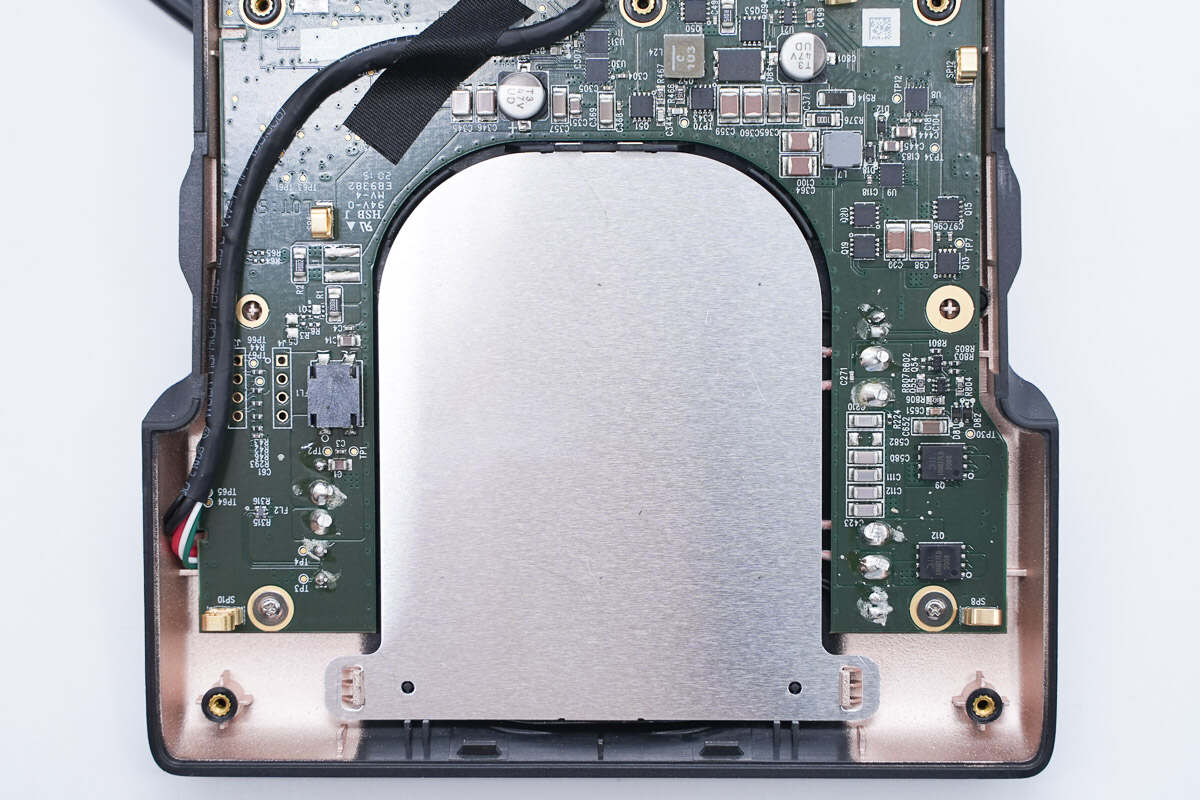
The aluminum plate is fixed by clips.
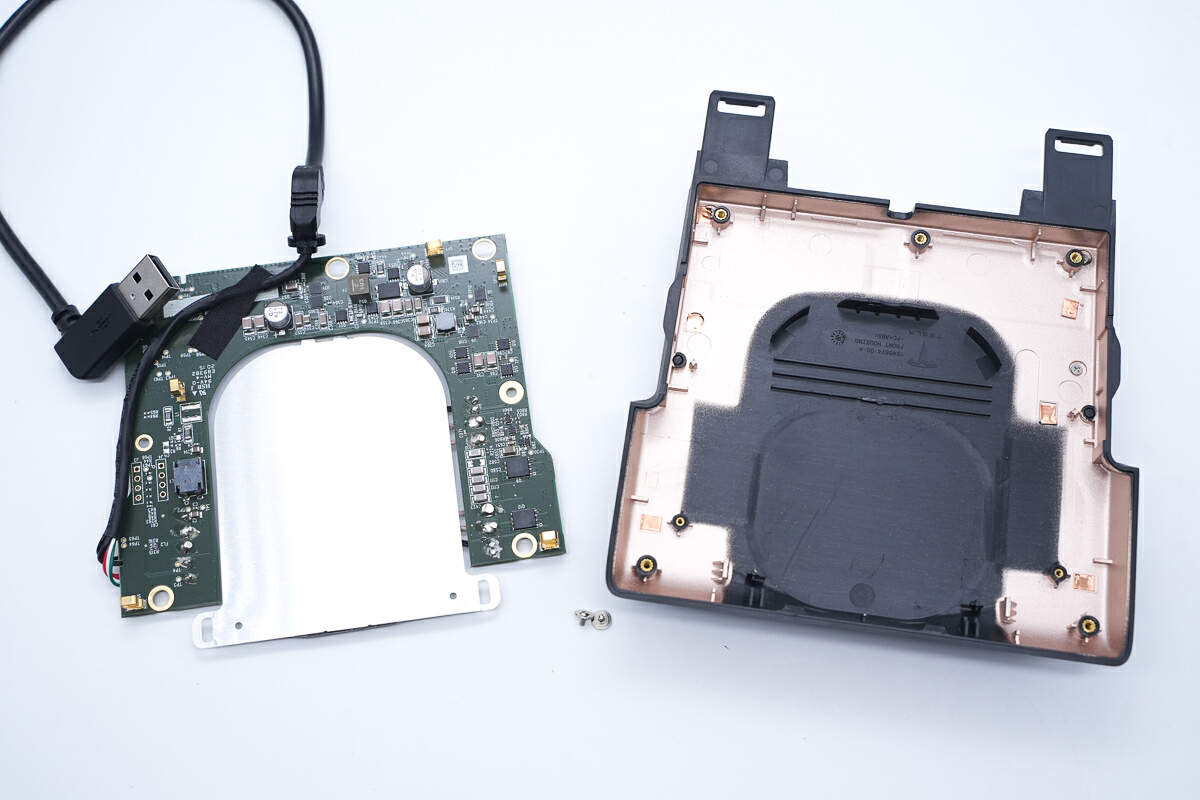
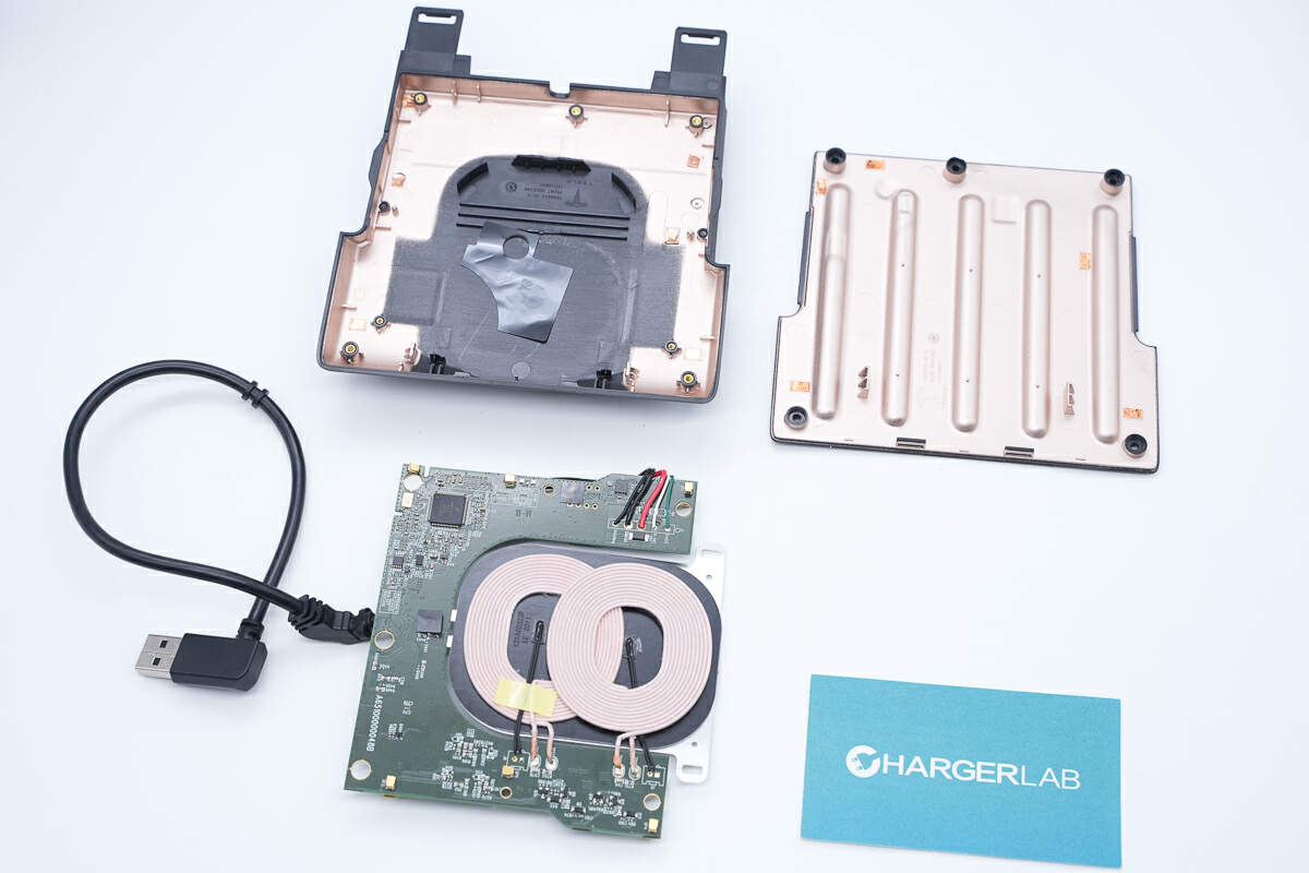
Take out the PCBA module.
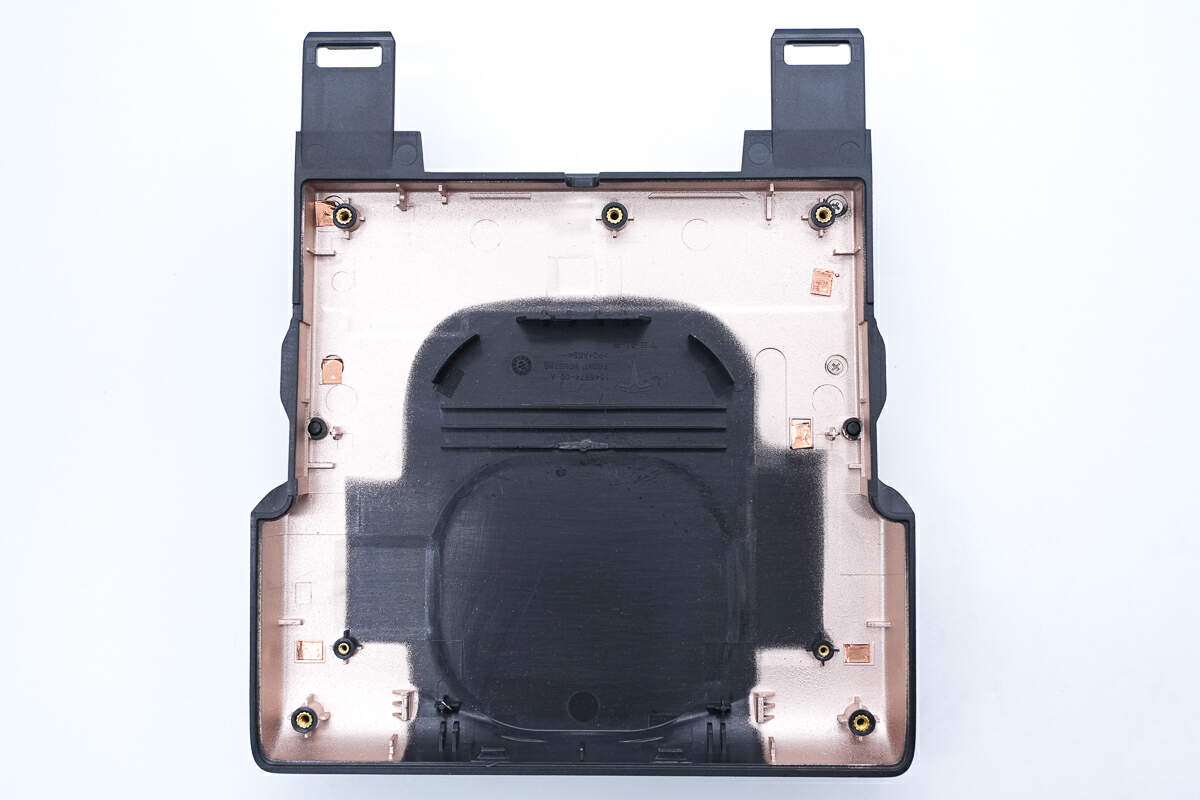
The inside of the shell is also shielded by metallization.
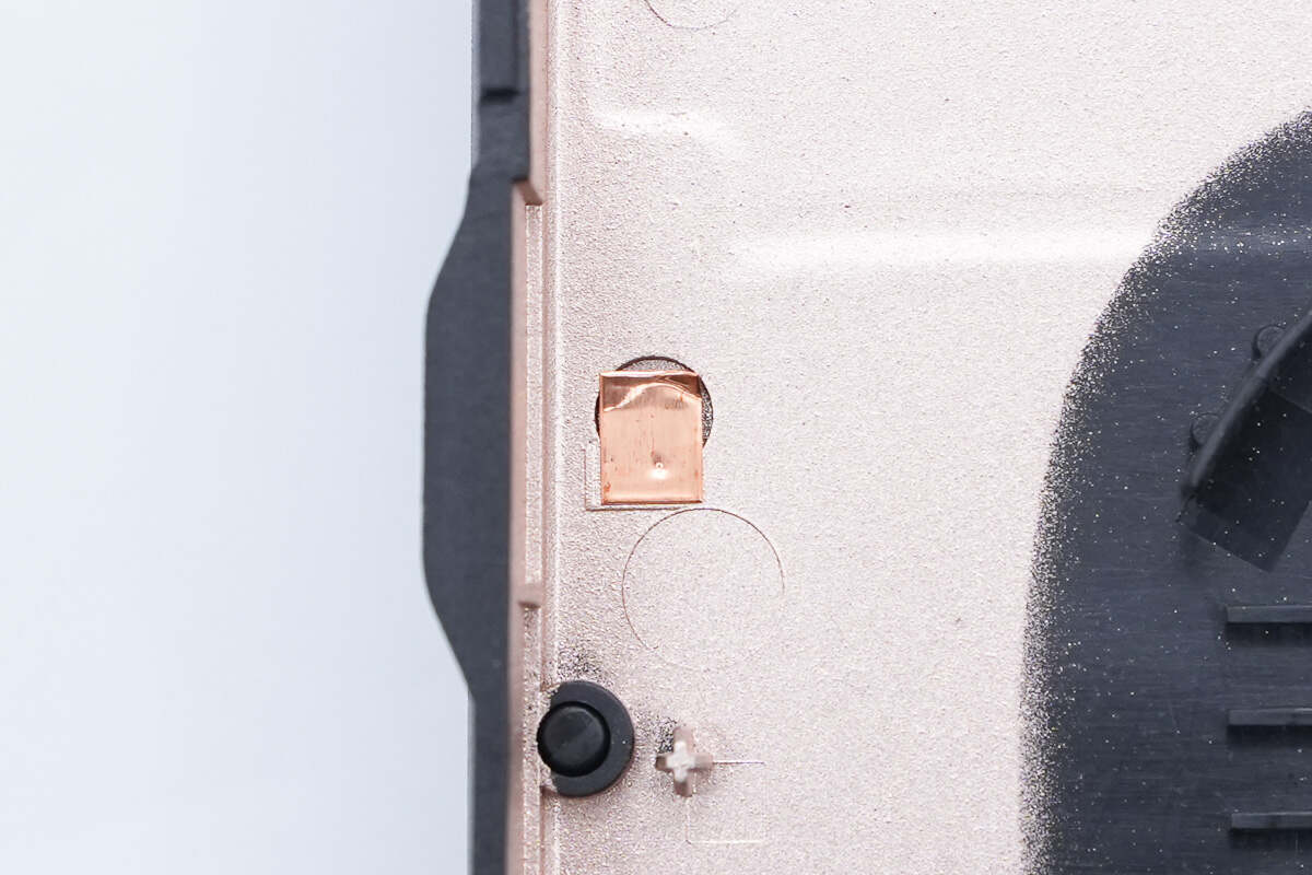
The conductive copper foil is pasted at the position corresponding to the PCB contact point.
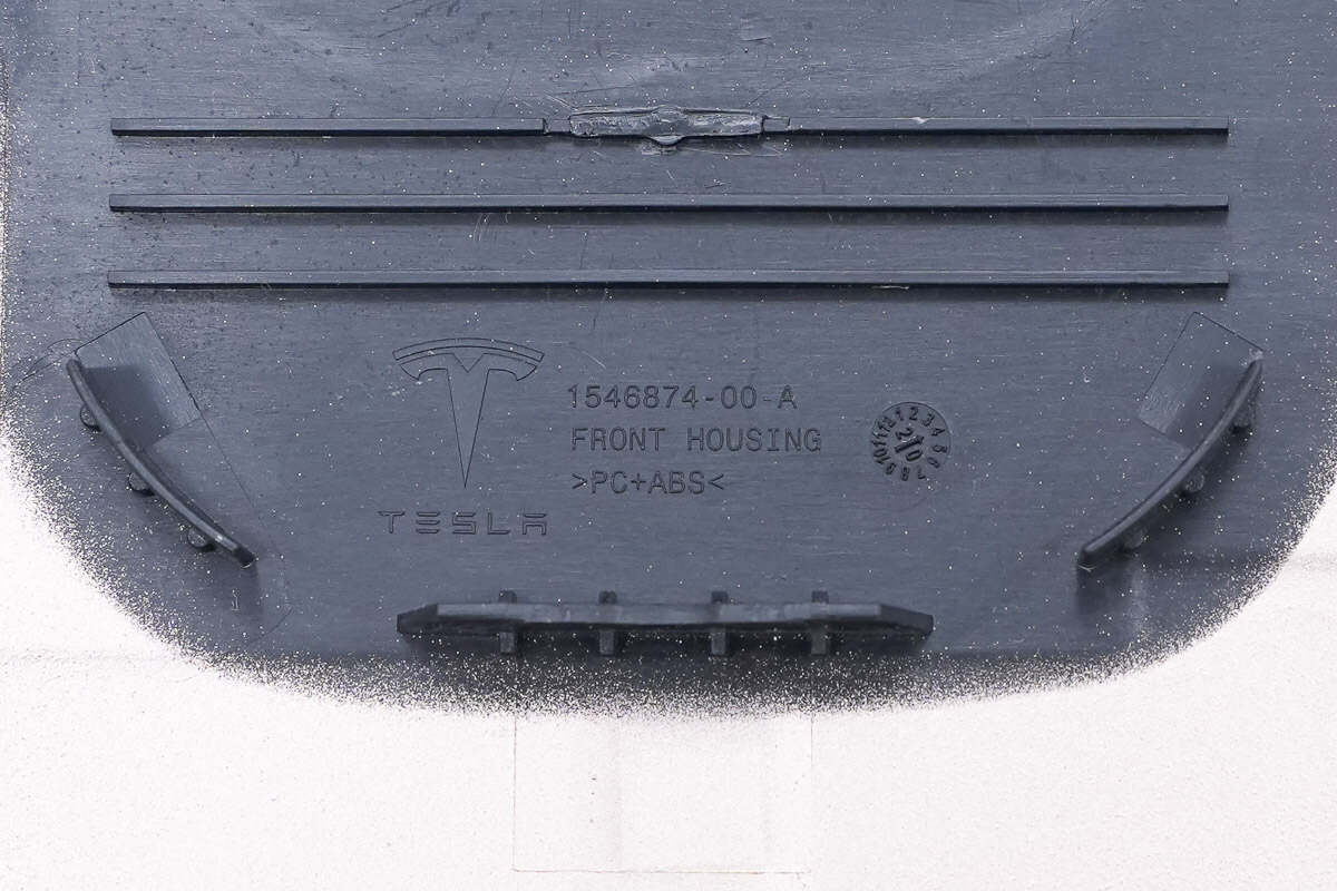
It is also made of PC+ABS.
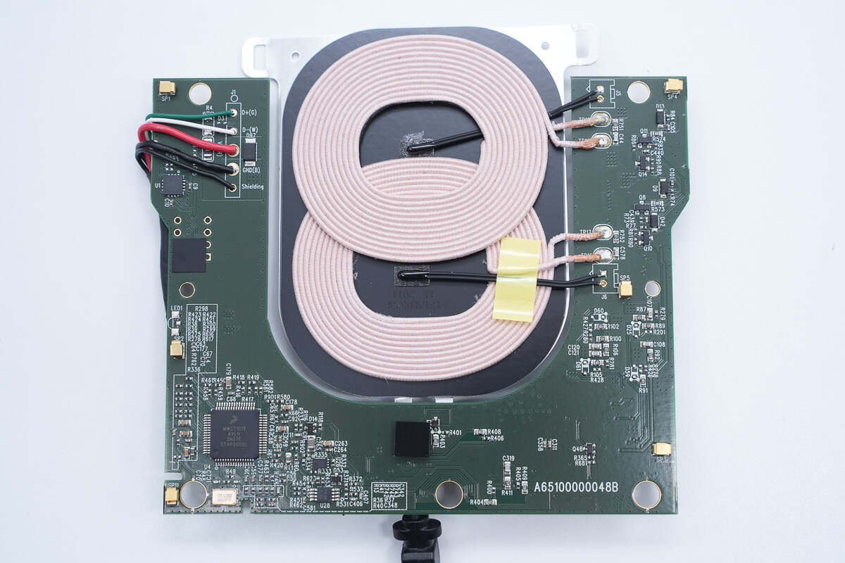
The input wires are welded on the front of the PCBA module, as well as the wireless charging master control chip, wireless charging coil, and thermistor.
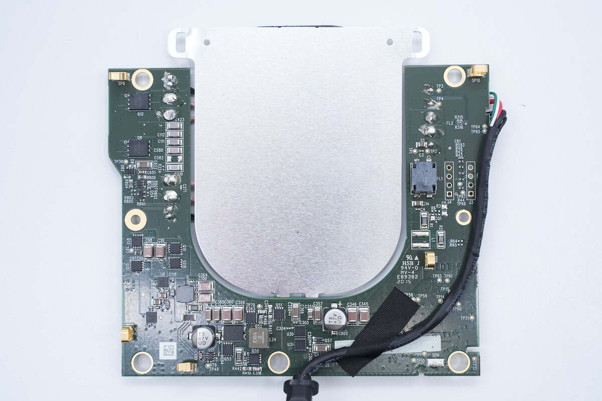
On the back are MOSFET, resonant capacitor, wireless charging power MOSFET, synchronous buck-boost circuit, and filter inductor.
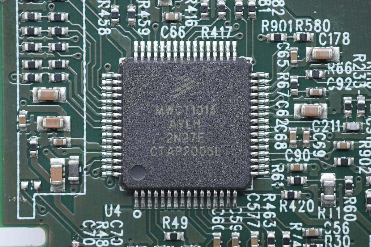
The wireless charging master control chip is from NXP and adopts LQFP64 package. It is an automotive-grade multi-coil wireless charging transmitter controller with integrated digital demodulation, fixed operating frequency, integrated synchronous buck-boost control, and power full-bridge control. Model is MWCT1013AVLH.
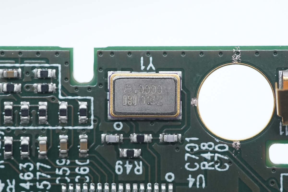
This is the external crystal oscillator. 8.000MHz.
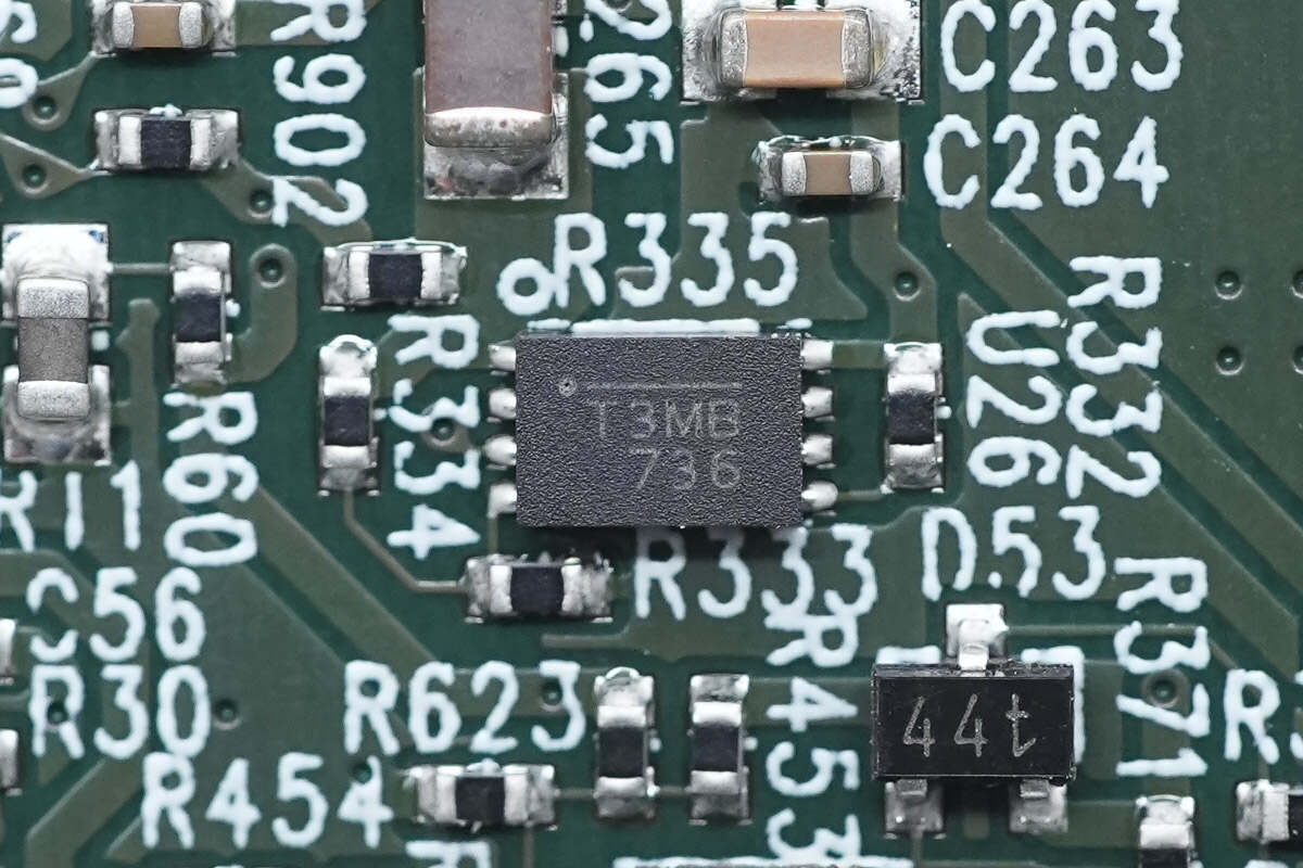
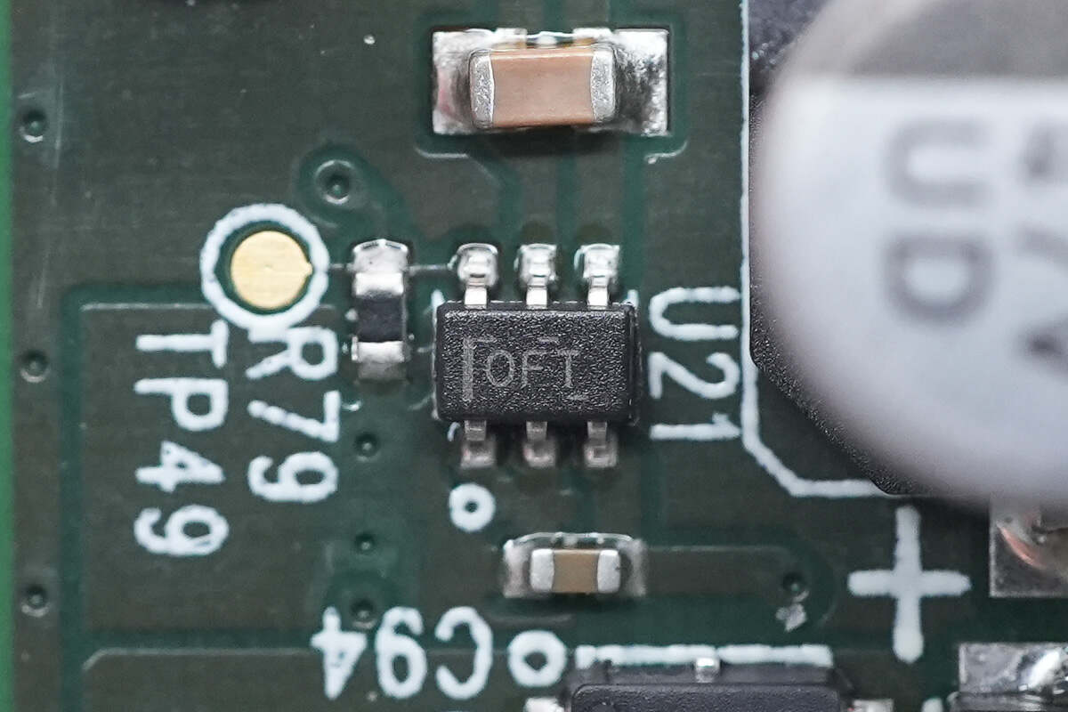
The voltage regulator chip used to power the MCU comes from MPS and is marked with T3. It is an automotive-grade 500mA output linear regulator that supports 2.5-6.5V input voltage, meets the AEC-Q100 standard for automotive applications, and adopts QFN-8 package. Model is MPQ8904.
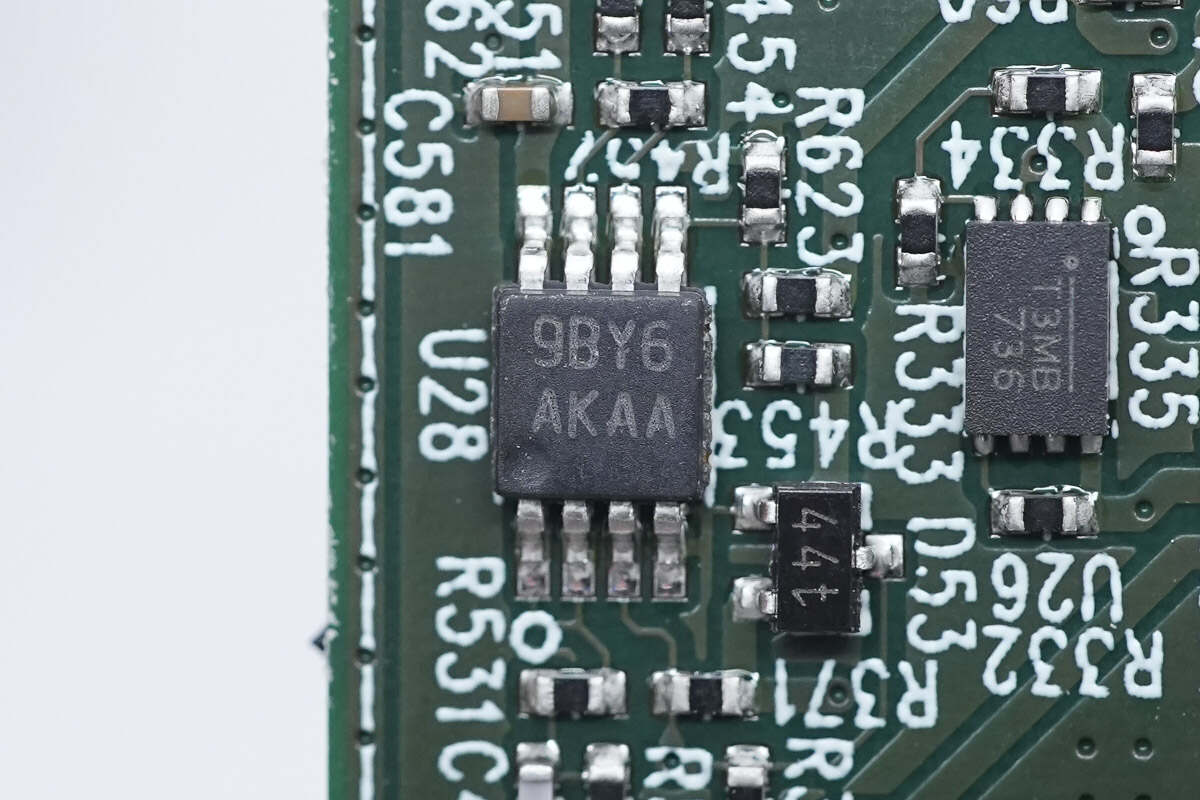
The dual Op Amp is from TI and marked with AKAA. It adopts VSSOP8 package. Model is LMV822-Q1.
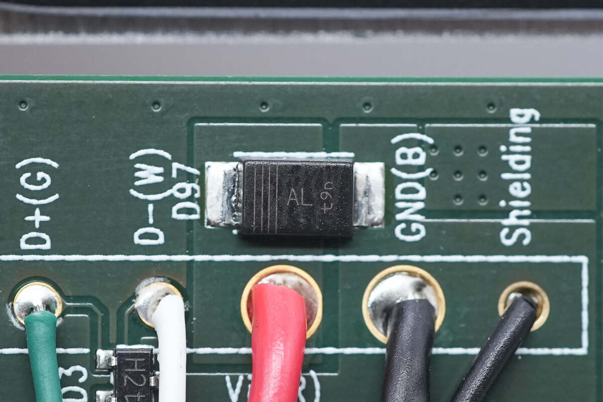
The TVS used for overvoltage protection is from Nexperia and adopts SOD-123W package. It is marked with AL. It has a withstand voltage of 20V and meets the AEC-Q101 standard. Model is PTVS20VS1UR.
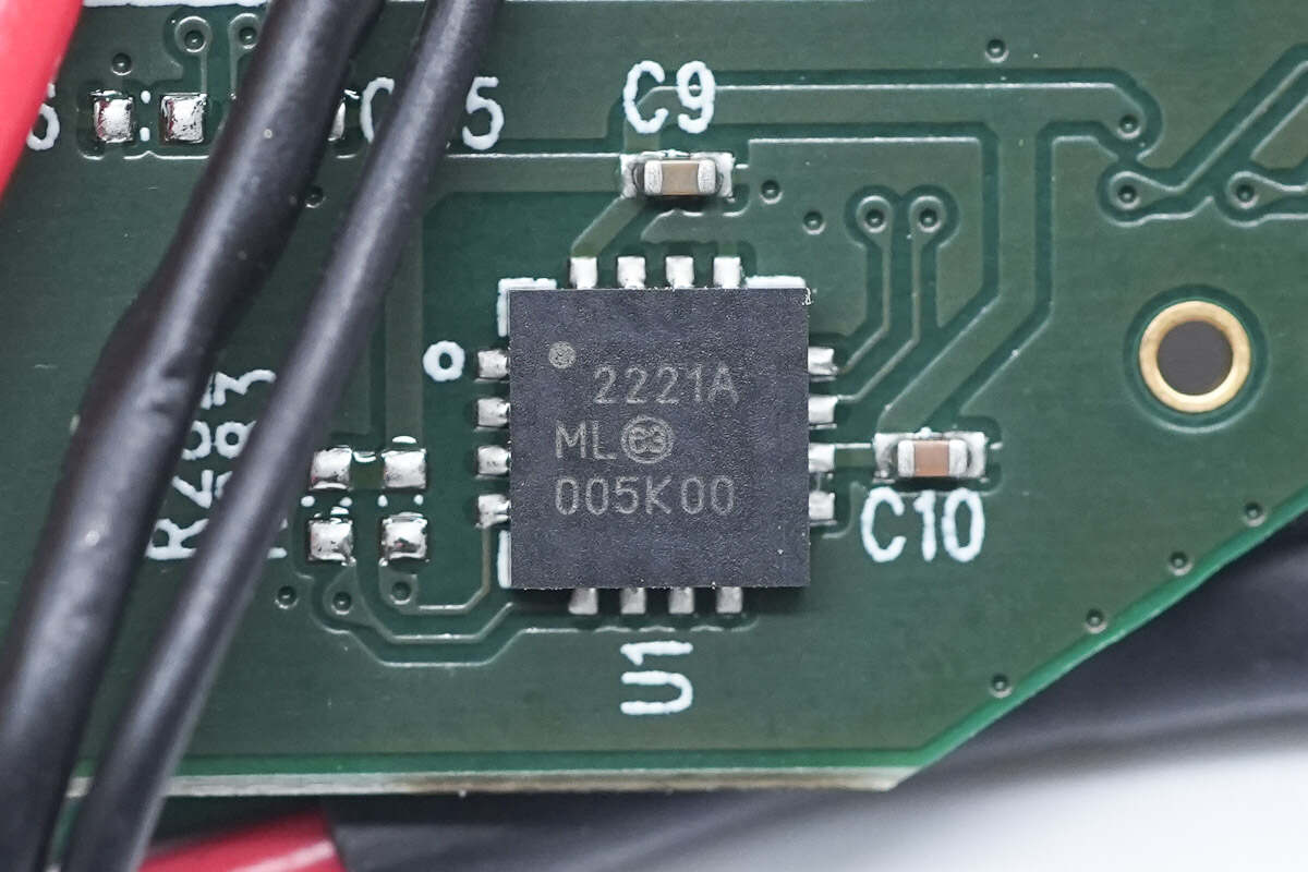
The USB 2.0 to I2C/UART protocol converter is from Microchip and adopts QFN4*4 package. It supports a full-speed USB connection, has a GPIO interface, can transmit I2C bus data through the USB interface, and meets the AEC-Q100 standard. Model is MCP2221A.
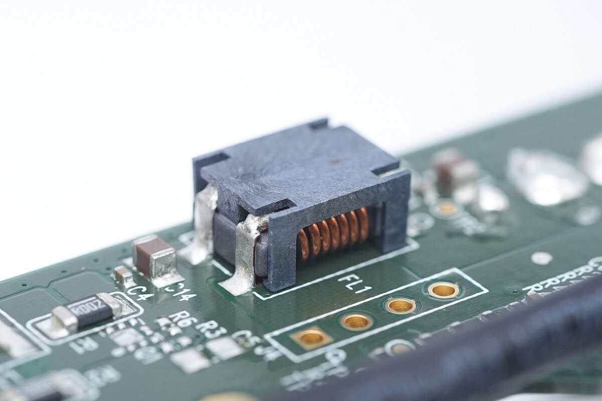
The filter inductor is soldered by chip.
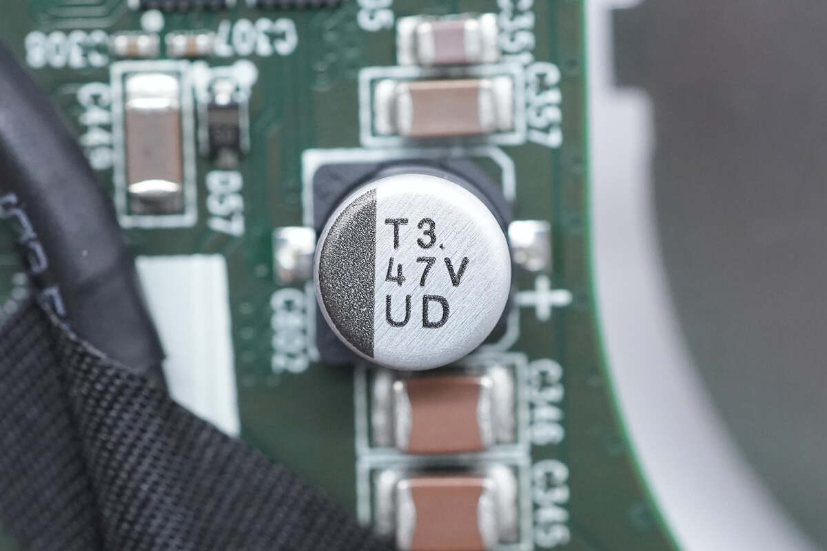
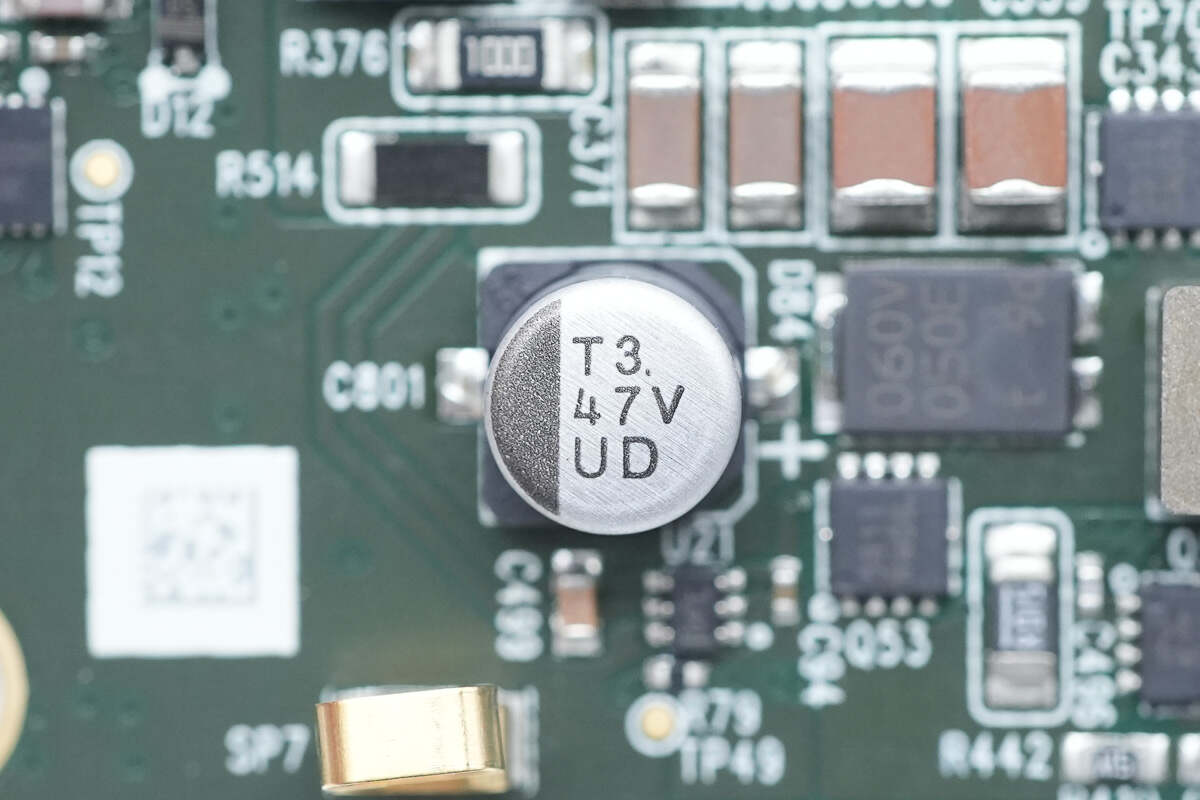
The electrolytic capacitor is connected in parallel with MLCC capacitors for input filtering. The filter capacitor is from nichicon, a UUD series low-resistance chip capacitors that meet AEC-Q200 standards. 47μF 35V.
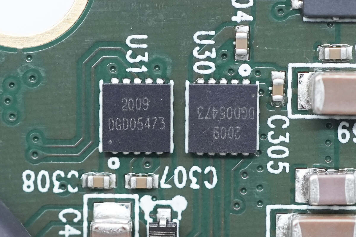
The two half-bridge drivers for driving the synchronous buck-boost circuit MOSFET are from DIODES and adopt U-DFN3030 package. Model is DGD05473.
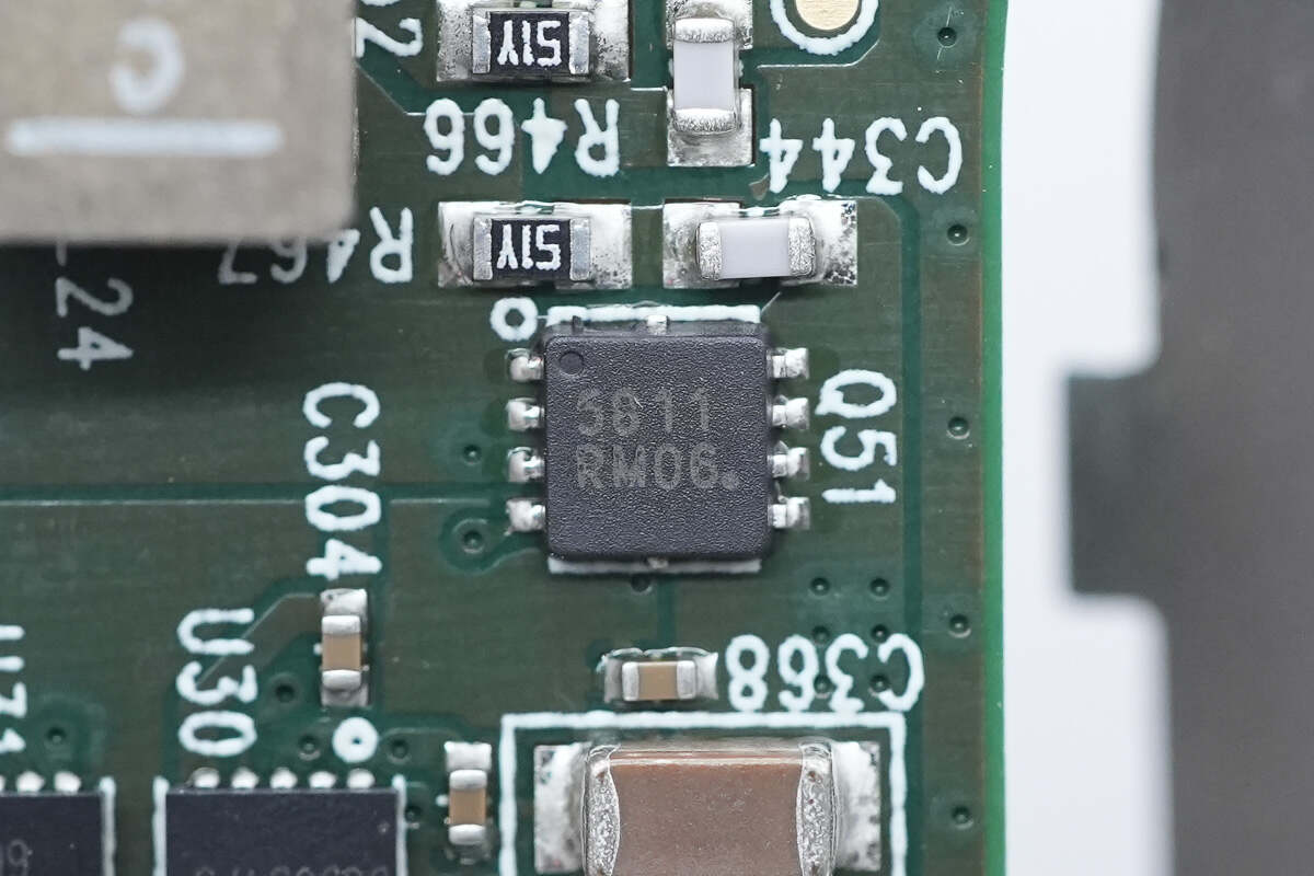
The synchronous buck-boost MOSFET is from onsemi and adopts WDFN8 package. 40V 6.7mΩ. Model is NVTFS5811NL.
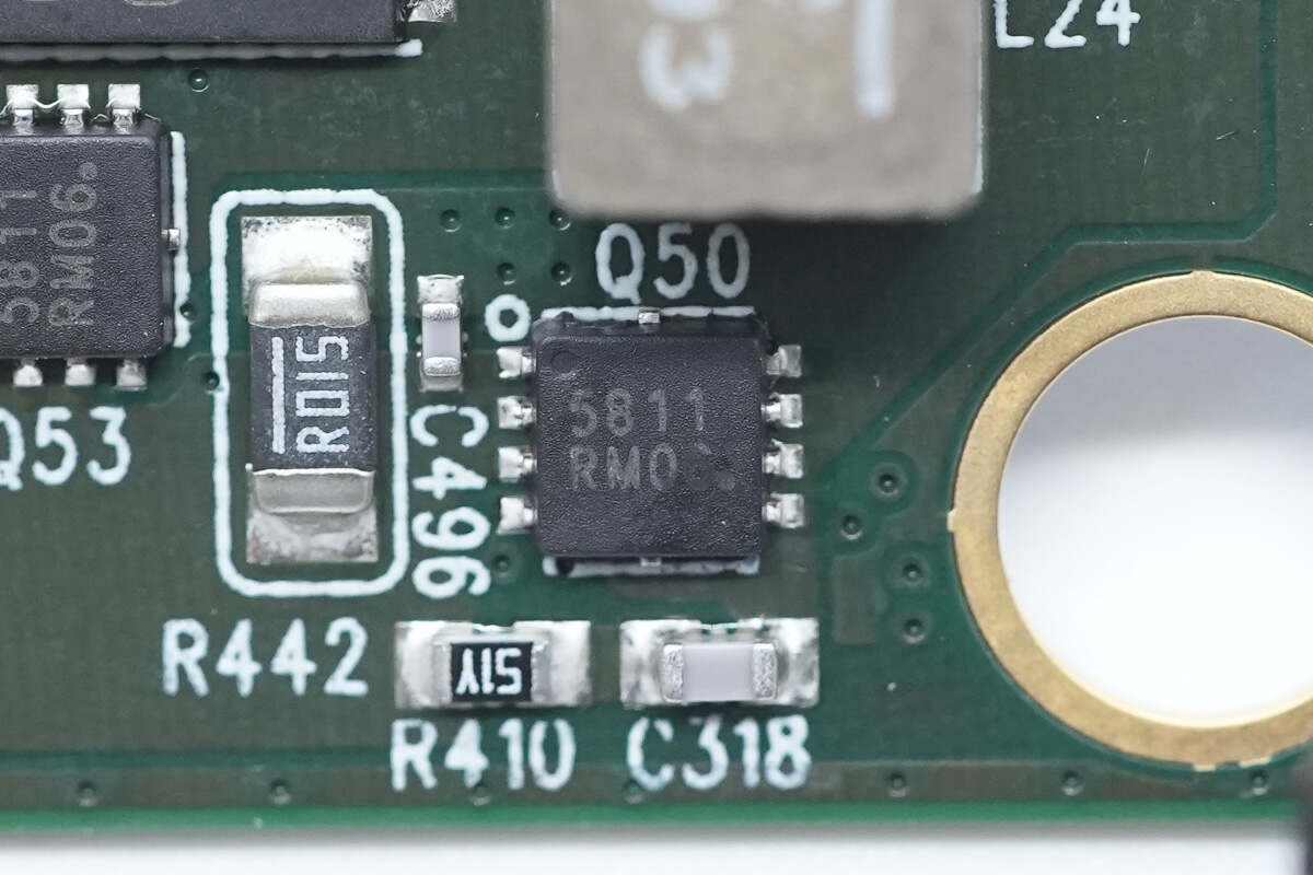
The input NMOSFET model is the same, and a sampling resistor is provided on the left side for current detection. 15mΩ.
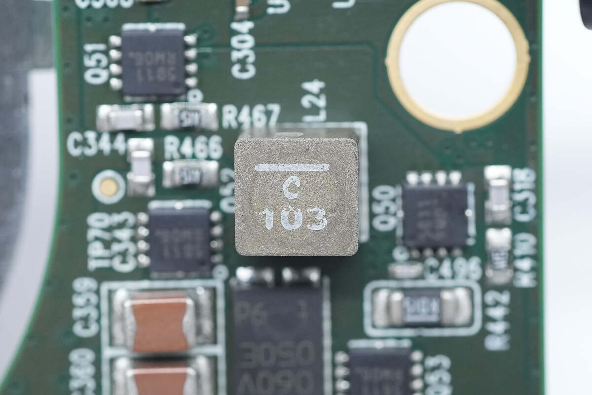
The alloy inductor used for buck-boost voltage conversion is from Coilcraft. 10μH.
The output PMOSFET model is the same.
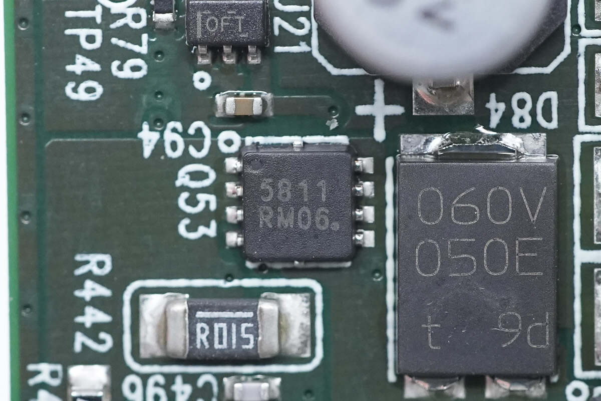
The output NMOSFET models are the same.
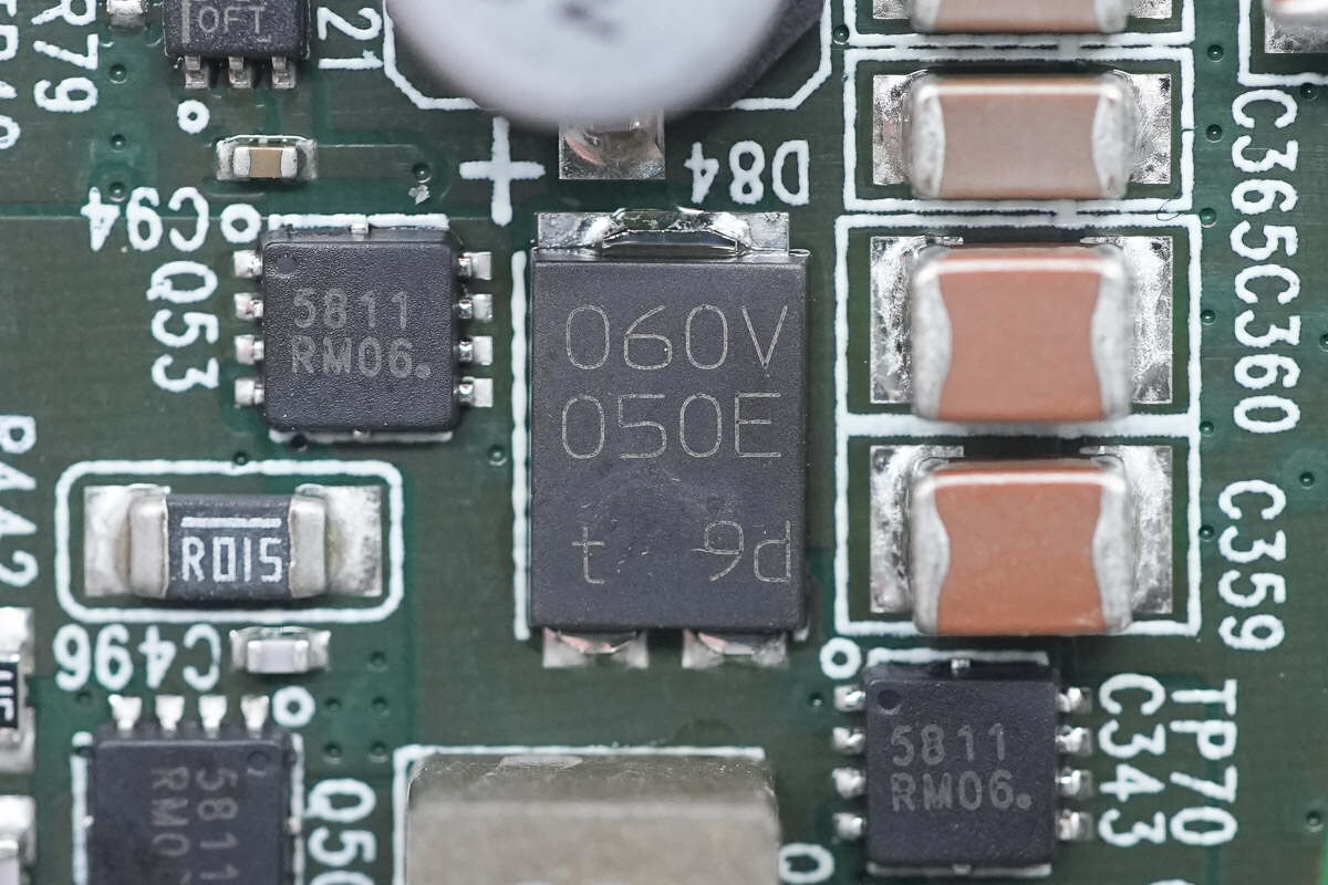
The Schottky diode is from Nexperia and adopts SOT1289 package. It is AEC-Q101 qualified. 60V 5A. Model is PMEG060V050EPD.
The filter capacitor is from nichicon. 47μF 35V.
The current sense amplifier is from TI and adopts SC70 package. It is an automotive-grade bidirectional current sensor that meets the AEC-Q100 standard. Model is INA214-Q1.
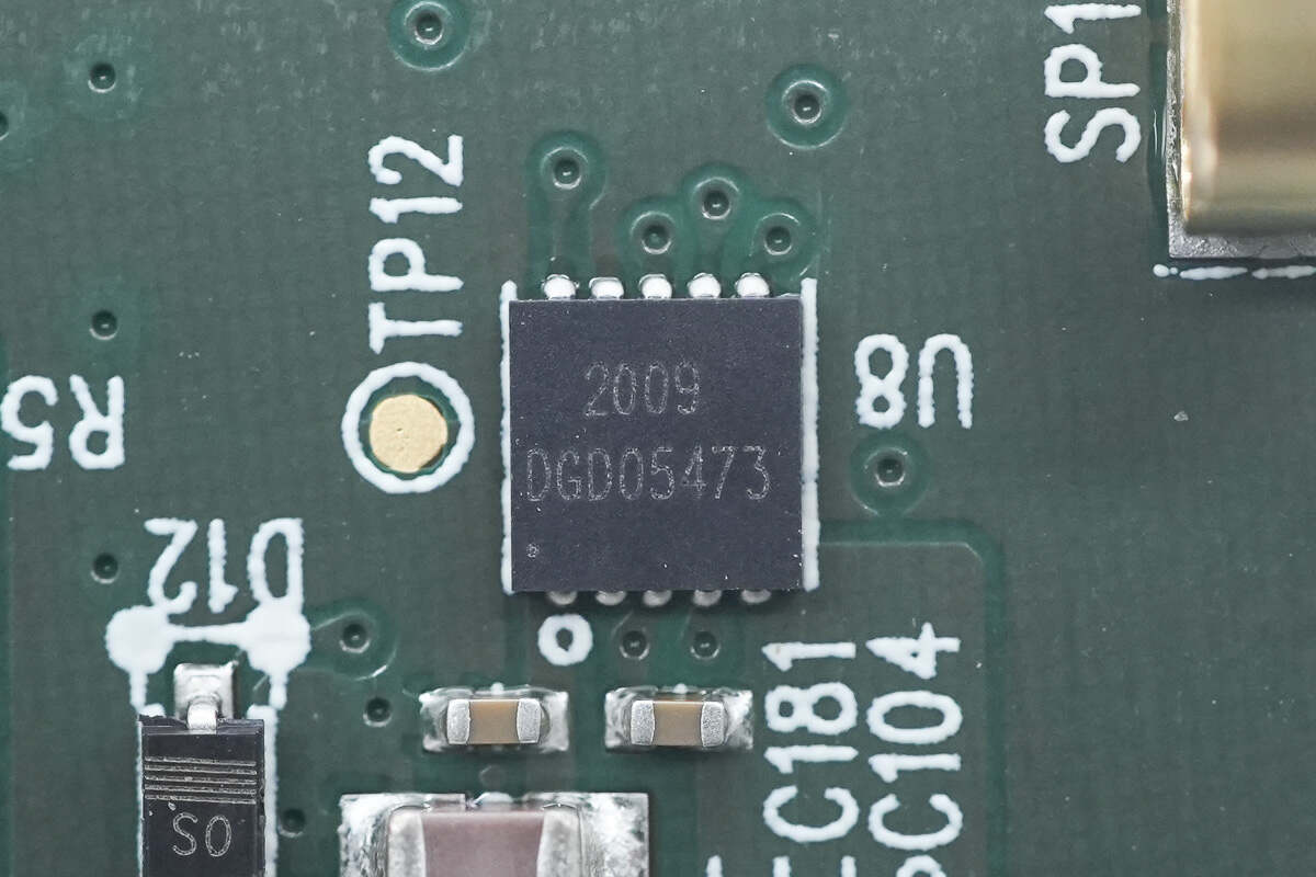
The half-bridge driver for driving the wireless charging power MOSFET is from DIODES. Model is DGD05473.
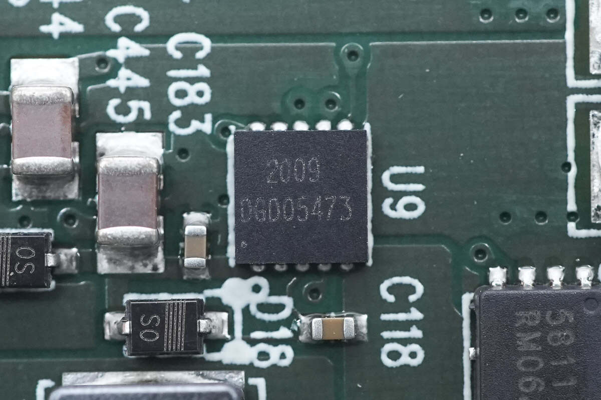
The other model is the same.
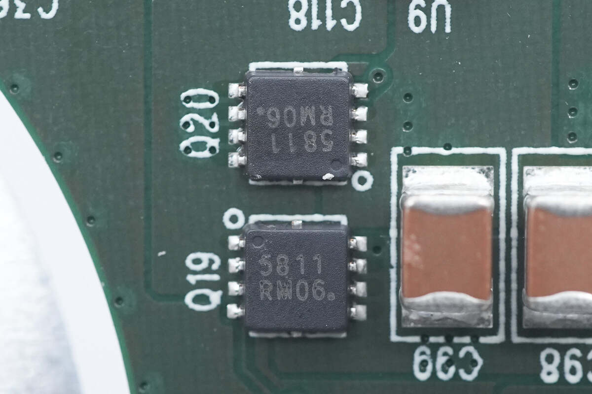
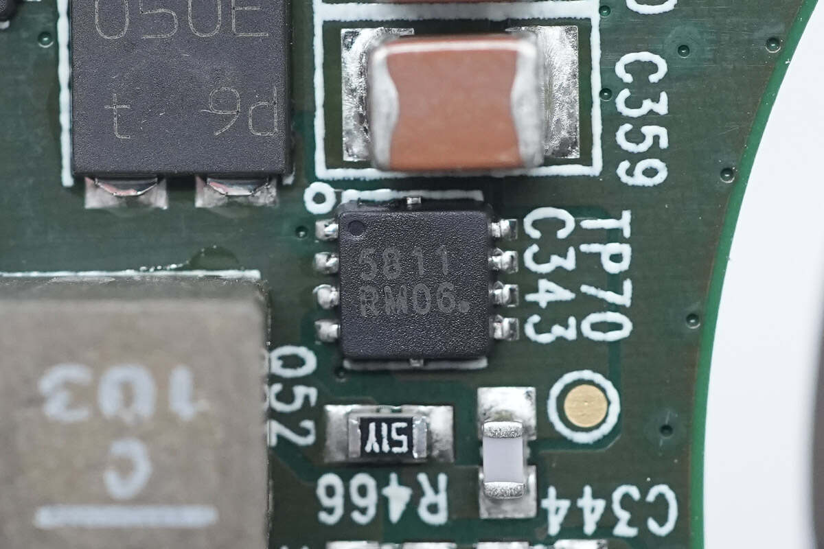
The power MOSFET for wireless charging is from onsemi. Model is NVTFS5811NL.
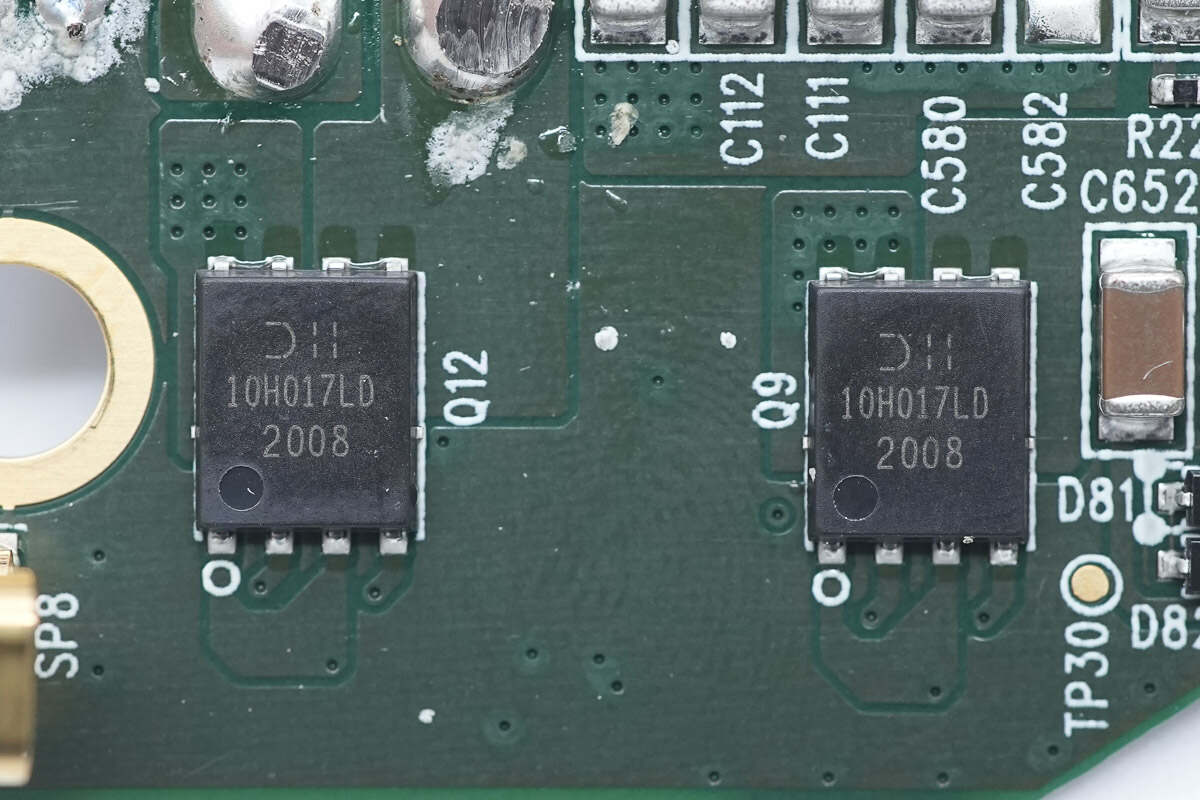
The MOSFET used for wireless charging coil switching is from DIODE and adopts PowerDI5060-8 package. 100V 17.4mΩ. Model is DMT10H017LPD.
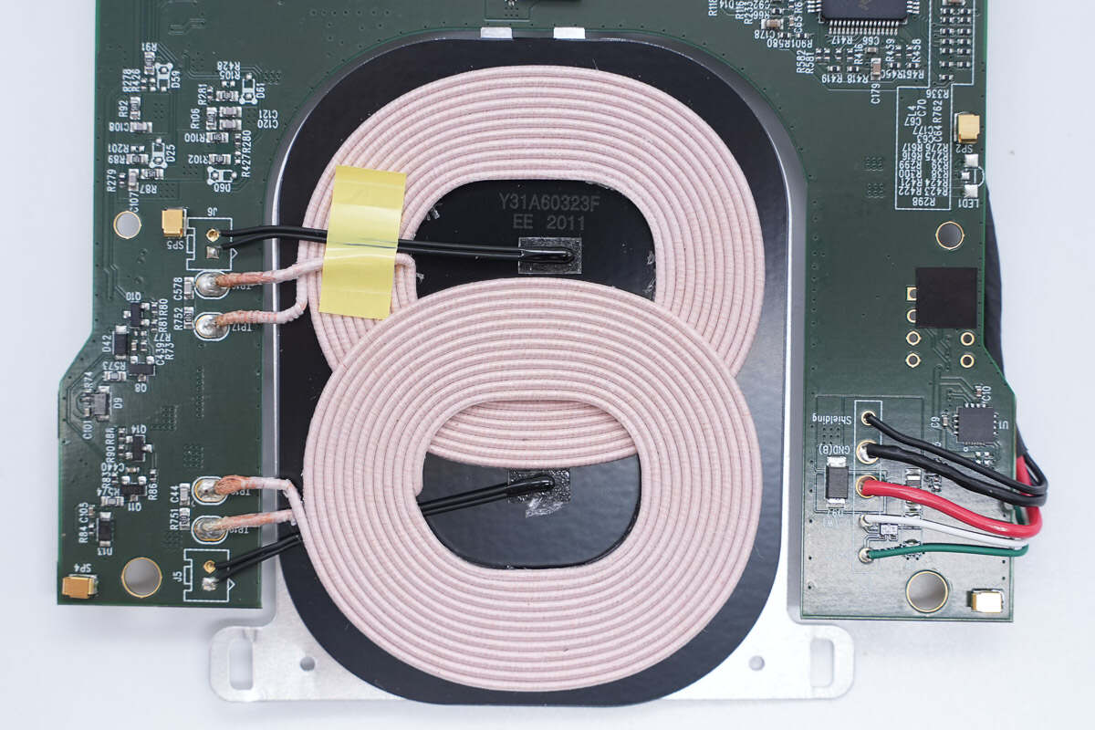
The two wireless charging coils are placed overlapping.
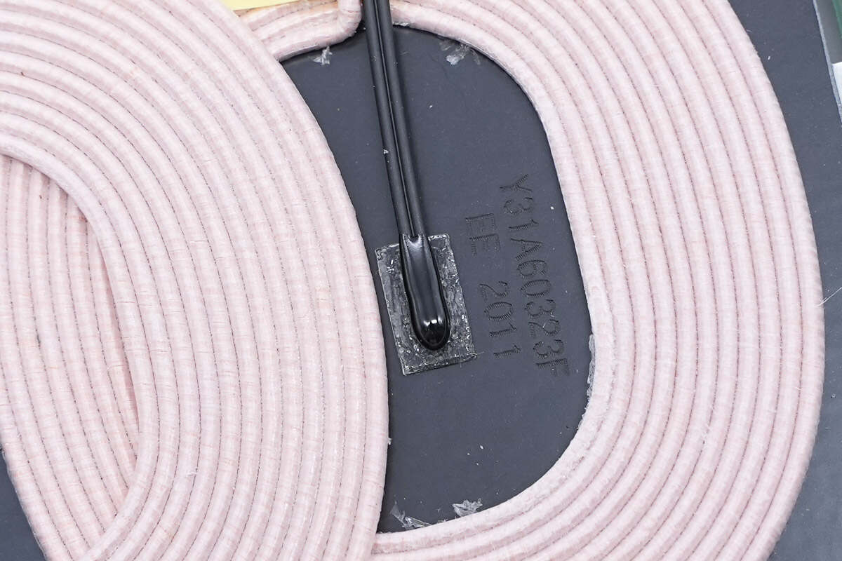
There is a thermistor in the center of the coil to detect the temperature.
Well, those are all components of the Tesla Wireless Phone Charger.
Summary of ChargerLAB
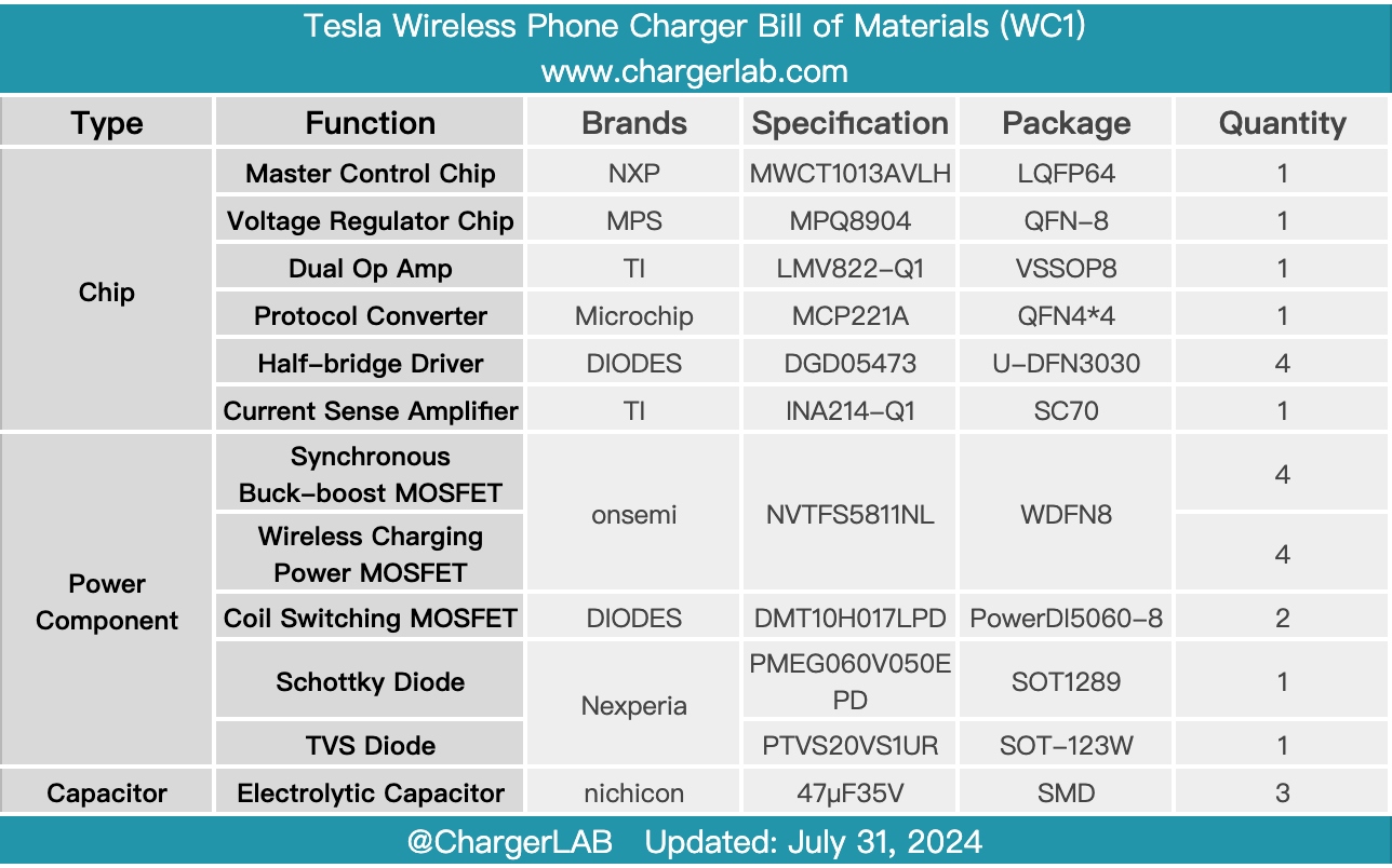
Here is the component list of the Tesla Wireless Phone Charger for your convenience.
Tesla's in-car wireless charger is officially produced for the early Model S and Model X that did not support wireless charging. It supports 7.5W output power and is powered by a USB-A port. It can charge one phone and fix the phone through the structural design.
After taking it apart, we found it uses the NXP MWCT1013AVLH master control chip with four DIODES DGD05473 drivers, which are used for synchronous buck-boost MOSFET and wireless charging full-bridge MOSFET driving, respectively. The inside of the shell is shielded by metallization, the shrapnel is welded on the PCB for contact and grounding, and automotive-grade components are used. The solution and materials are solid and reliable.
Related Articles:
1. Review of Tesla Wireless Portable Charger
2. 5000mAh | Teardown of Tesla Wireless Portable Charger (TSL02)
3. Teardown of Tesla Model Y 15W Wireless Charging Module