Introduction
As a pure electric vehicle, the Tesla Model Y not only has a very intelligent control system but also has interior configurations that keep up with the times. Model Y is equipped with an extra-large touch screen that displays all vehicle functions centrally and also supports rich functions such as voice interaction and games.
The front and rear rows of Model Y are each equipped with two USB-C ports, which can be used to charge phones and other devices, supporting a maximum power of 36W.
In addition to wired charging, the Tesla Model Y also supports wireless charging. The wireless charging module is located next to the front armrest box, which is convenient for phones to be charged wirelessly. The tilted placement makes it easy to check messages while charging.
Tesla Model Y Wireless Charging Experience
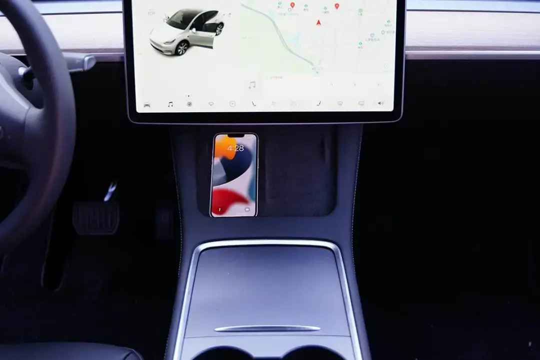
Place the iPhone 13 on the left side of the wireless charging panel and it can be charged normally.
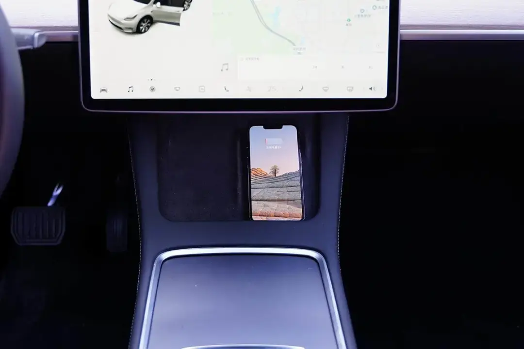
Place another iPhone 13 on the right side of the wireless charging panel and it can be charged normally.
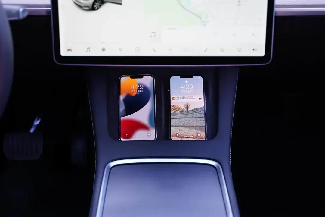
When two iPhone 13s are on it simultaneously, they can be charged normally. After observing for a while, there was no interruption in charging.
Teardown
We remove the wireless charging module from the car, and then we'll take it apart.
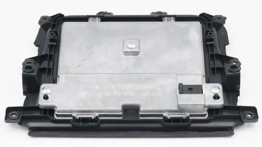
The front of the module is covered with suede, which is non-slip and comfortable to the touch. It also adopts a partitioned design, which can meet the wireless charging needs of the driver and co-pilot seats at the same time. It can also ensure that the phone is stable and does not slip while driving. There are fixing holes and fixing posts on the edge of the module.
The back of the module is covered with a large metal heat sink, which is fixed with three hexagonal screws and four clips at the bottom.
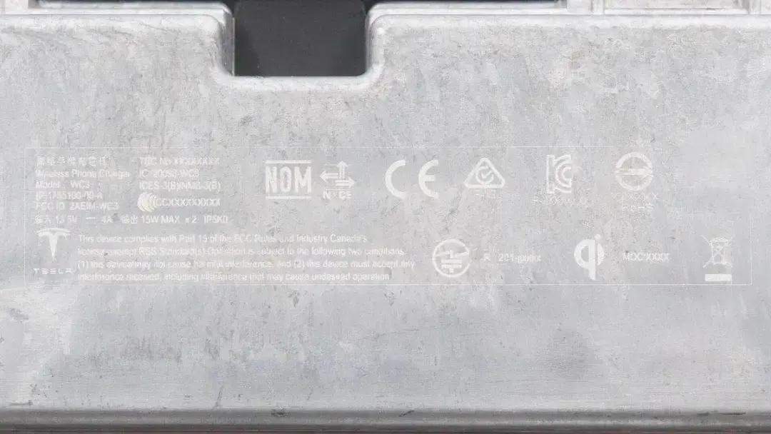
There are some specs info on the metal heat sink. Model is WC3. It can support input of 13.5V 4A. And it can support a maximum output of 15W. It supports the Qi standard and has passed NOM, NYCE, CE, KC, RoHS, and other certifications.
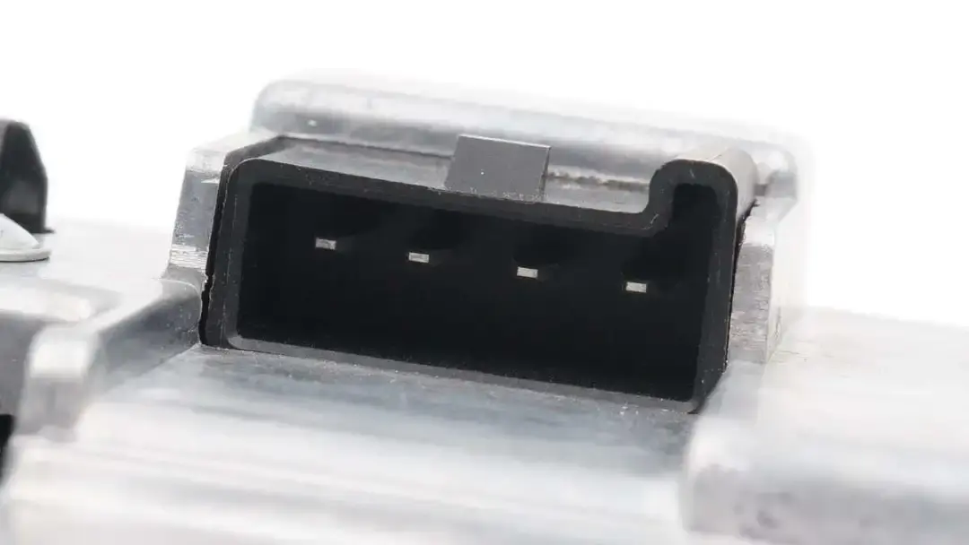
There is a buckle on the case of the power socket.
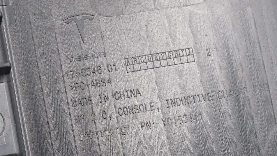
The plastic sheet of the module is made of PC + ABS fireproof material.
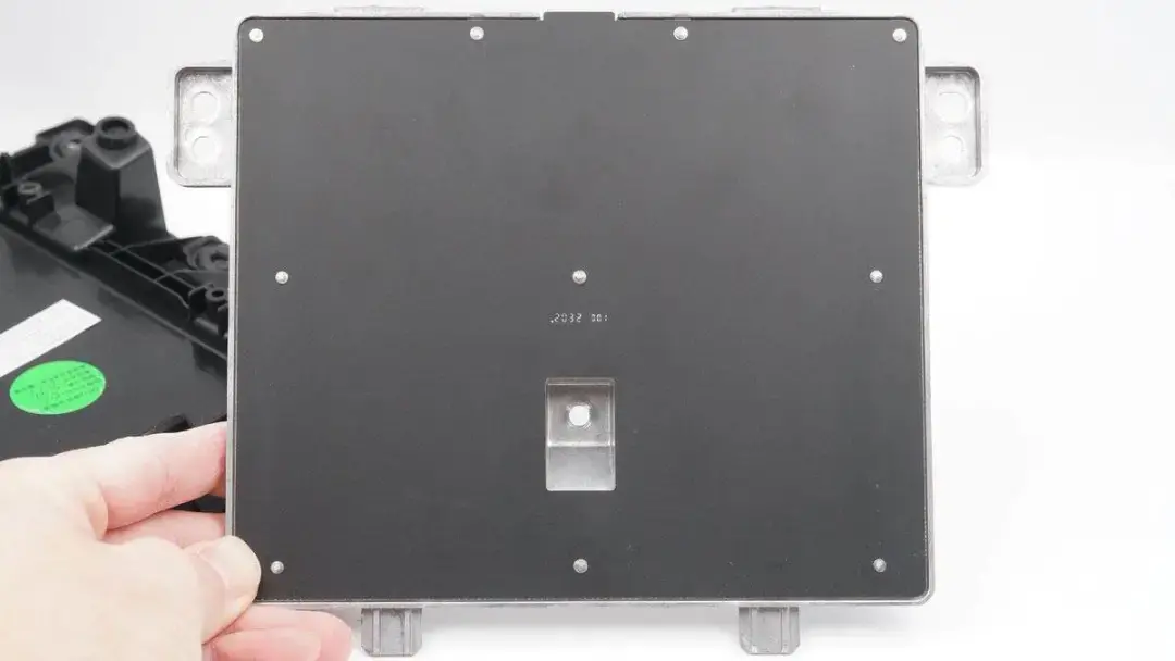
The front of the wireless charging coil module is covered with a fiberboard and coated with black.
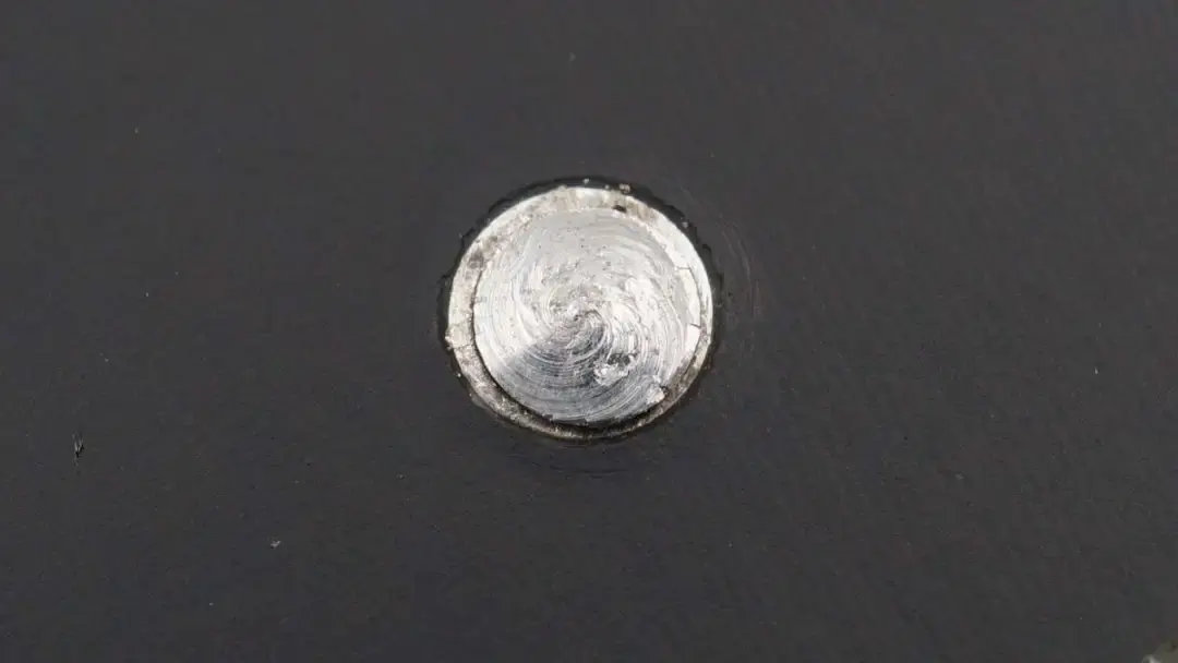
The fiberboard is fixed with ten metal pillars.
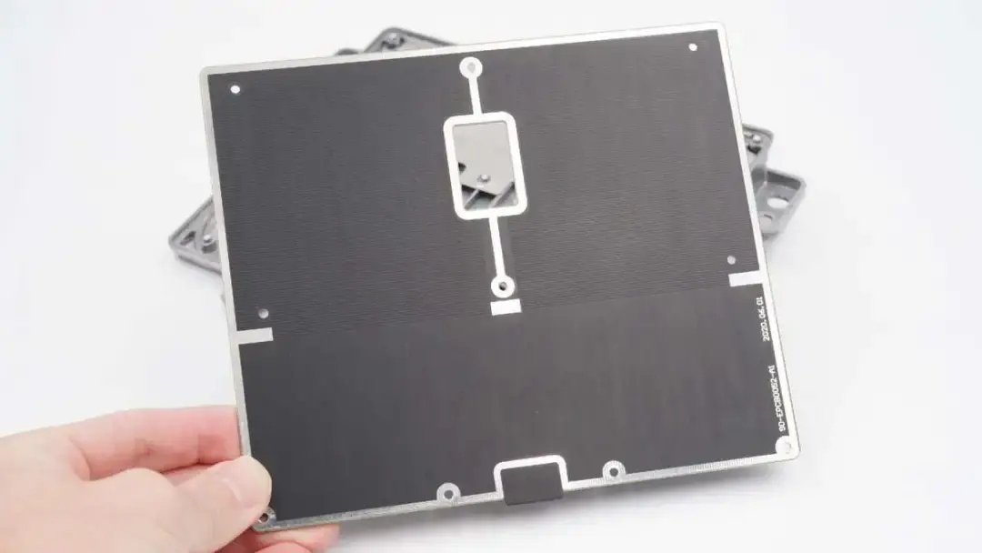
Remove the fiberboard.
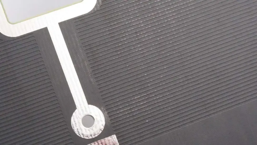
The area corresponding to the wireless charging coil is covered with grid-like copper to improve the heat dissipation effect.
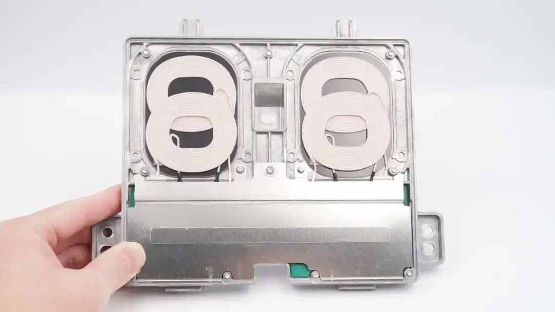
There is a wireless charging coil on the top and a metal plate covering the PCB below.
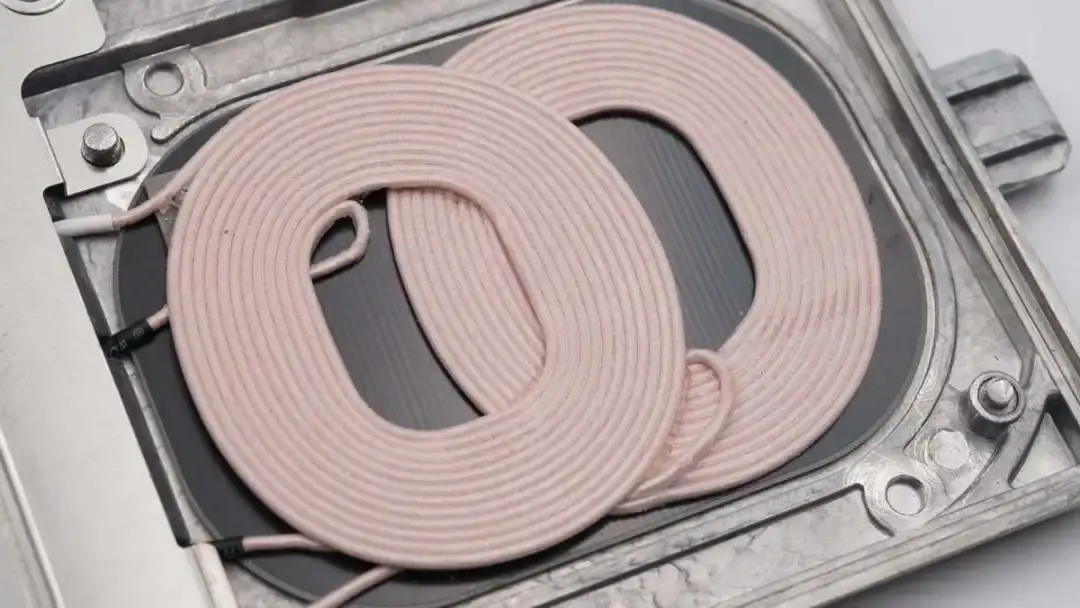
Each wireless charging area has two coils.
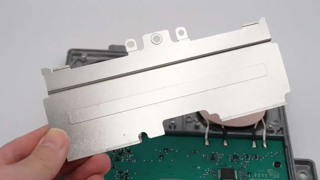
Remove the metal plate on the PCBA module.
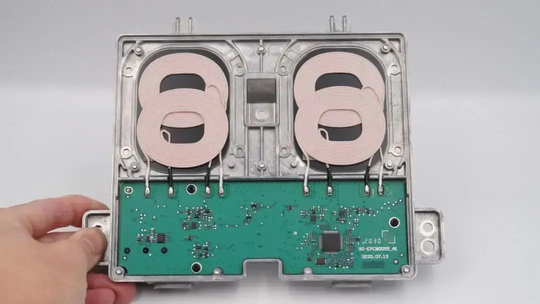
The PCBA module is fixed with screws and fixing posts.
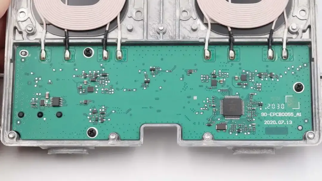
The wireless charging coil is soldered to the PCBA module.
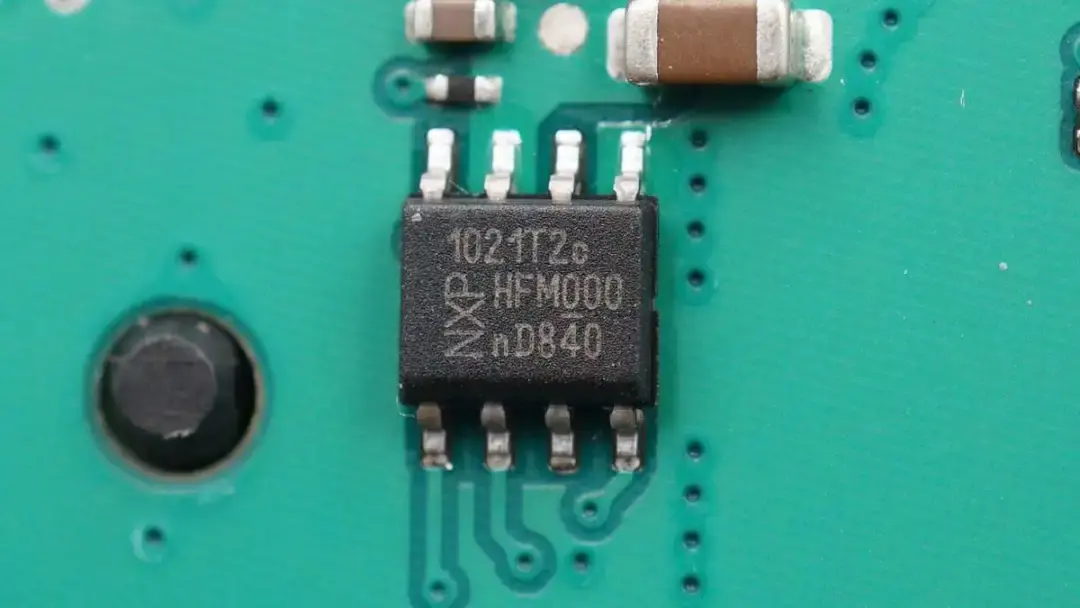
The protocol controller is from NXP. It can work with the master control chip to control the wireless charging and reduce energy consumption. Model is TJA1021.
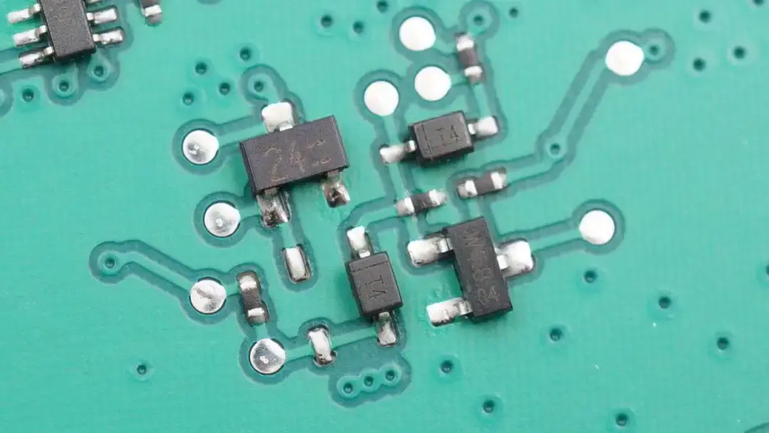
These are transistors and diodes used for signal processing.
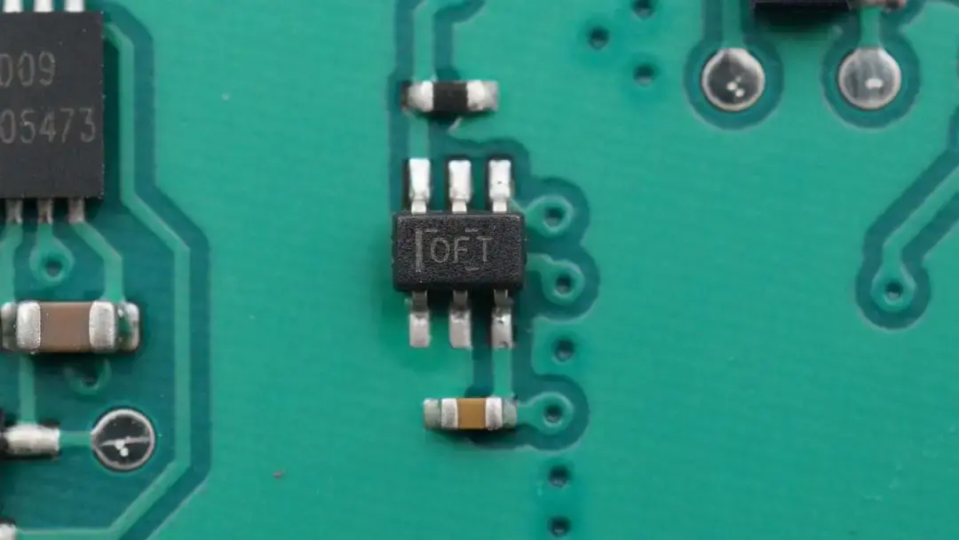
This is a bidirectional high-precision current sense amplifier, which comes from TI and is used for input current detection.
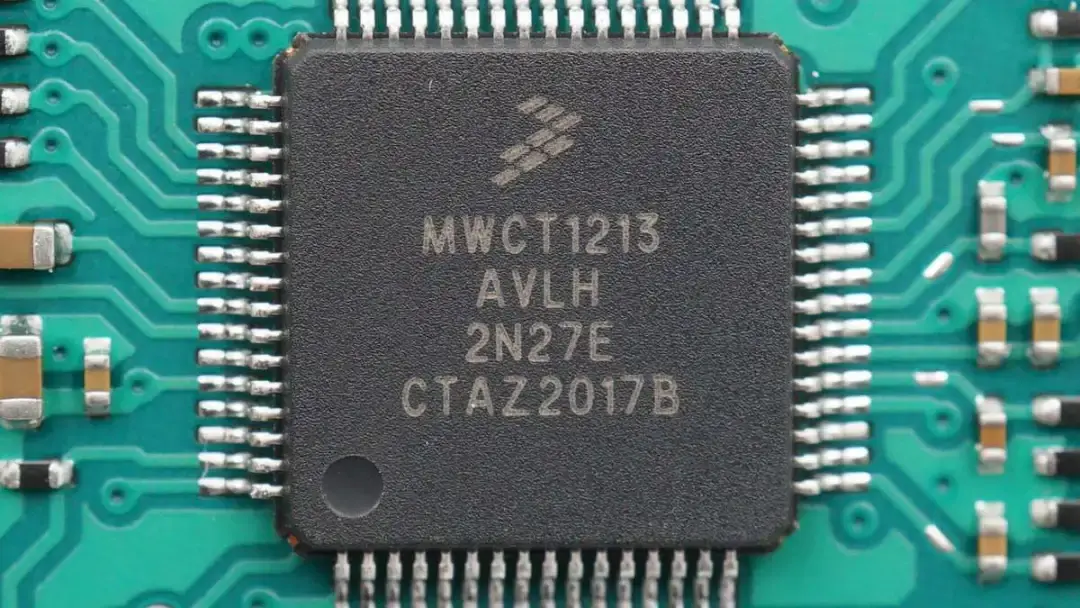
The master control chip comes from NXP. It can support a wide range of inputs of 5-24V and Qi 1.2.4 standard. And the maximum output power is 15W. Model is MWCT1213AVLH.
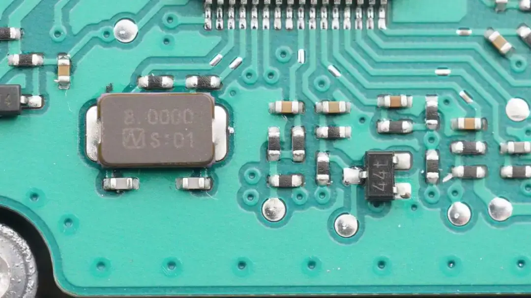
Those are passive crystal oscillator and some external components.
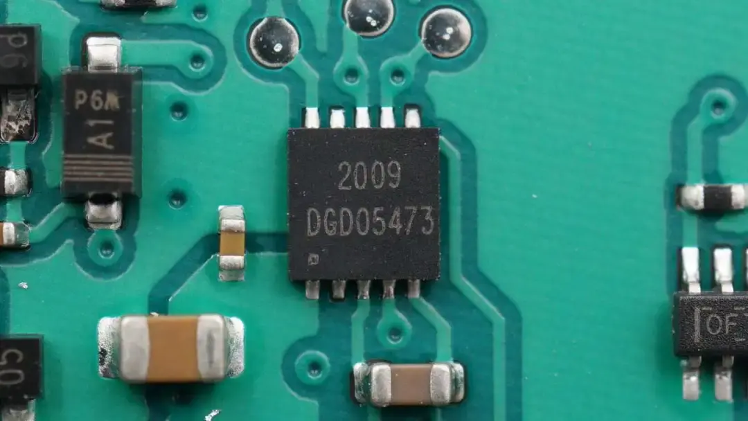
The half-bridge driver used for wireless charging MOSFET driving is from DIODES. There are four in total, two for each circuit. Model is DGD05473.
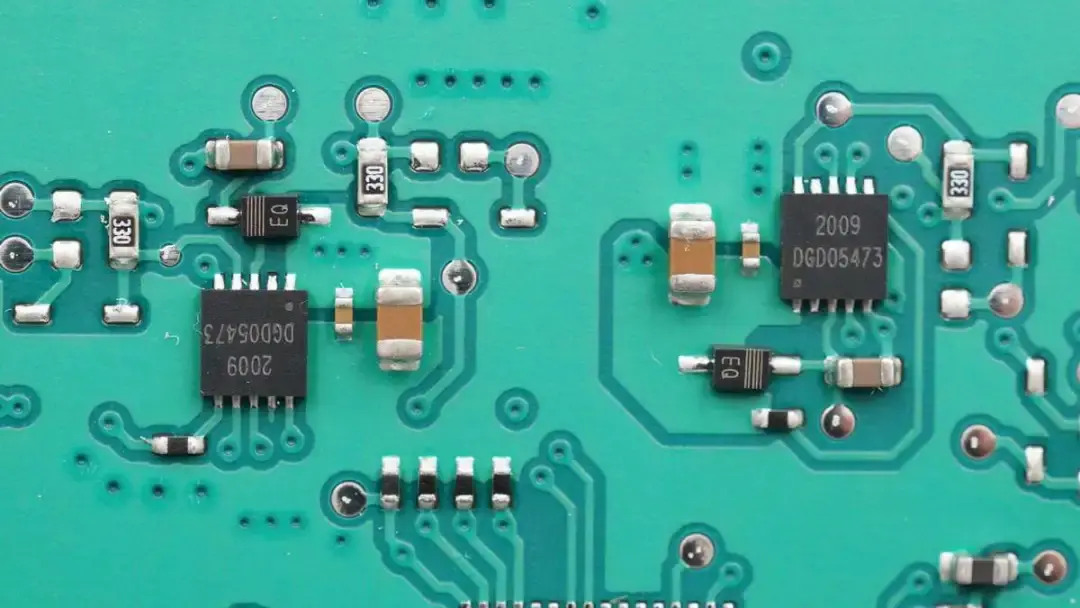
The other two half-bridge drivers are for wireless charging. Model is DGD05473.
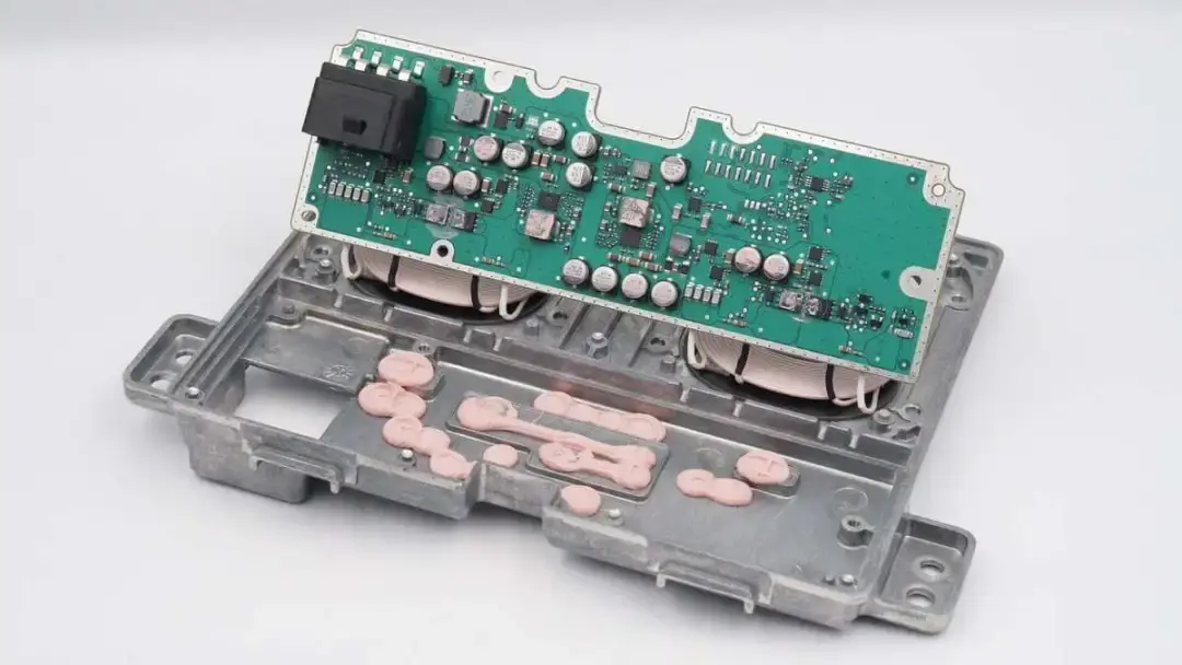
The PCBA uses potting compound to dissipate heat from components.
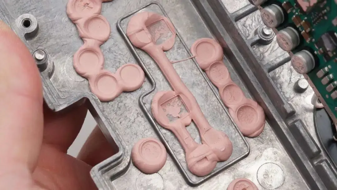
There are potting compounds.
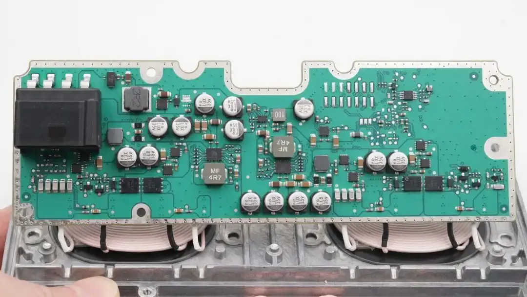
There are two independent buck-boost circuits and corresponding wireless charging full-bridge MOSFETs on the PCBA, as well as switching MOSFETs for the two coils.
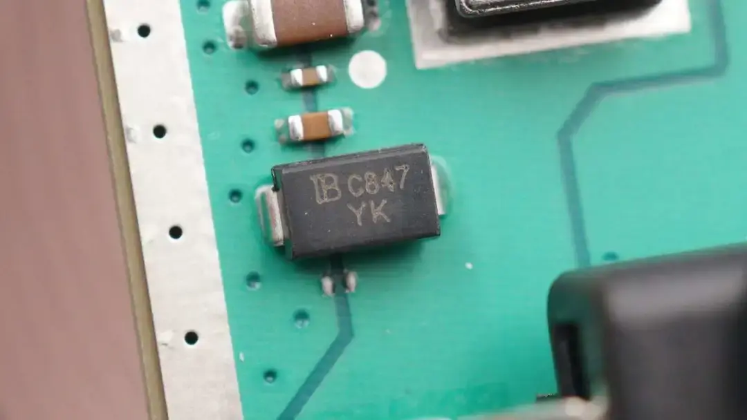
This is a TVS diode for input protection.
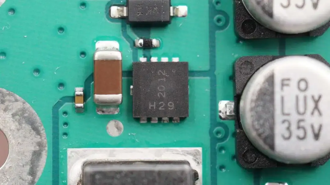
MOSFET for input protection, from DIODES.
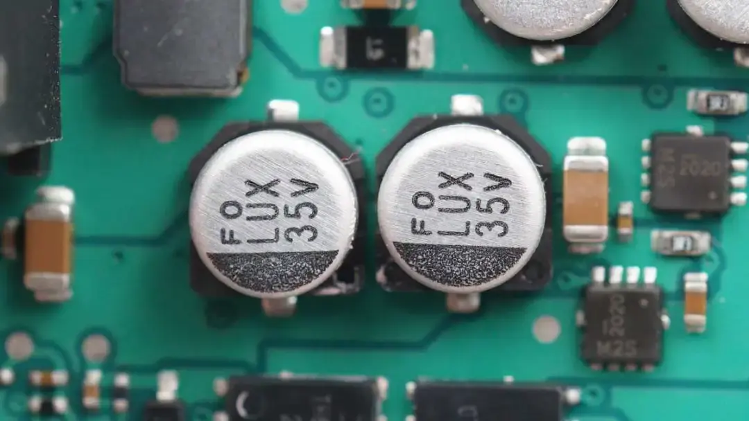
Two electrolytic capacitors are connected in parallel. The withstand voltage is 35V.
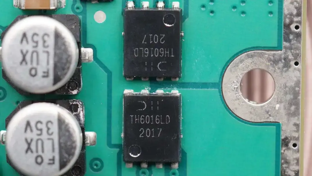
There are a total of 14 identical capacitors on the PCB. Those two switching MOSFETs come from DIODES used to switch between two coils. Model is TH6016LPDQ.
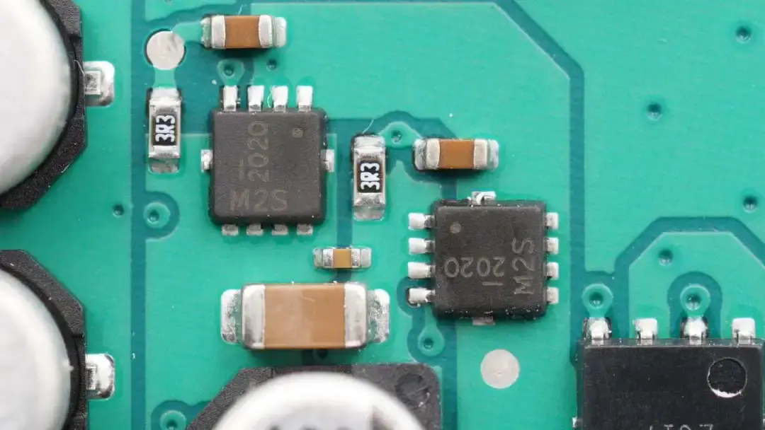
There are eight identical MOSFETs used for dual output of wireless charging from DIODES. Model is DMT47M2SFVWQ. 40V 7.5mΩ.
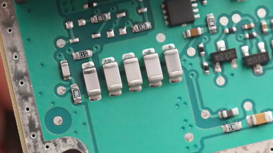
There are five white NPO resonant capacitors.
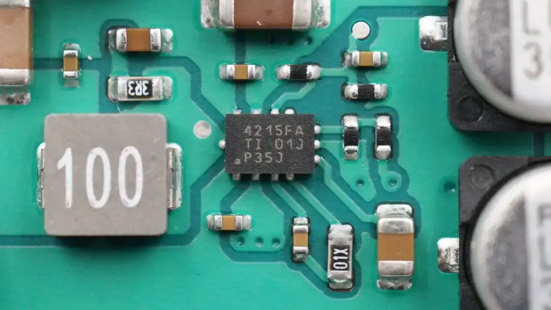
This is a TI ultra-small synchronous buck converter, which supports an input voltage of 42V.
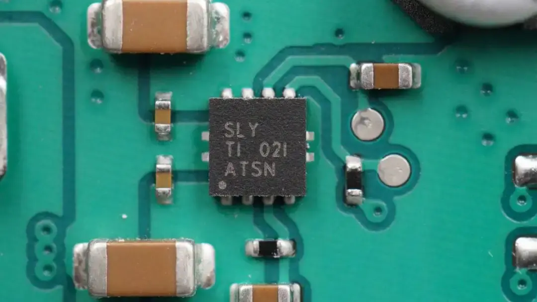
The adjustable output regulator can power the master control chip from TI. Model is TPS7A8101.
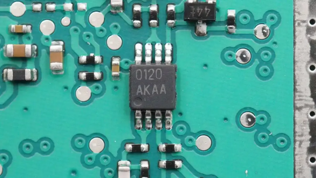
The dual op-amp is marked with 0120.
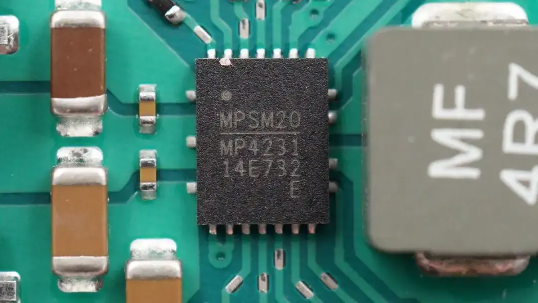
The synchronous buck-boost converter used for voltage conversion of wireless charging is from MPS. Model is MPQ4231.
Well, that's all components of this wireless charging module.
Summary of ChargerLAB
Tesla Model Y is equipped with two Type-C ports in the front and rear rows, but it still has a wireless charging module between the driver and co-driver seats. The aim is to increase charging options and provide greater convenience. This wireless charging module supports the qi wireless charging standard and is compatible with most brands of mobile phones on the market. The charging power is between 5-7.5W, and the official nominal total power can reach 15W.
After taking it apart, we found the most impressive part is the heat dissipation structure. It can adopt a large heat sink without considering the weight and have enough space to enhance heat dissipation performance. And rest of the components also come from well-known brands, such as NXP, DIODES, MPS, and TI. So, the overall quality is pretty good.
Related Articles:
1. How Fast Does Tesla Model Y Charge Your Devices - ChargerLAB Compatibility 100
2. Teardown of Tesla Model Y 15W Wireless Charging Module
3. Latest Teardown of Tesla Model Y Charging Module

