Introduction
Last year and this year, we posted two videos of the Microinverter from Enphase, which are IQ8X and IQ7+, respectively, you can click the related article on the bottom to check them out. And today, we got something different - an embedded power optimizer module from SolarEdge. Its output and functionality are configured within the module. Inside, this optimizer utilizes a synchronous buck/boost design, supporting a wide input voltage range. Now, let's delve into the teardown of this SolarEdge 330W Power Optimizer Module to examine its internal components and structure.
Product Appearance
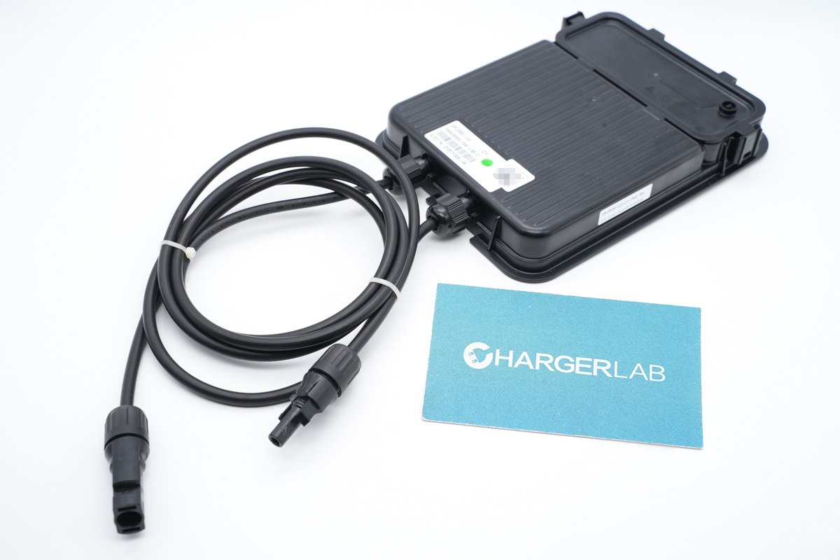
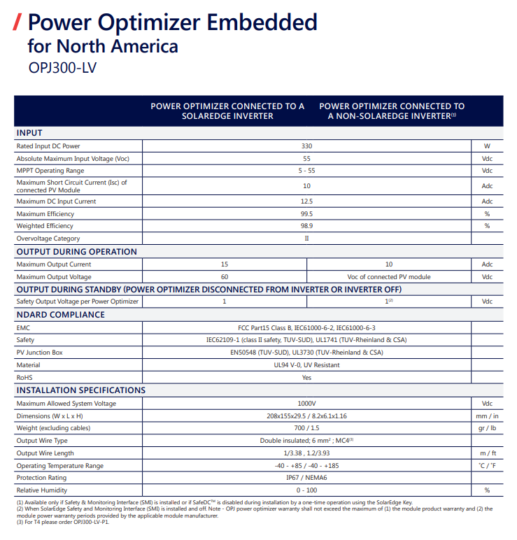
It comes with two input cables to be connected to the solar panels
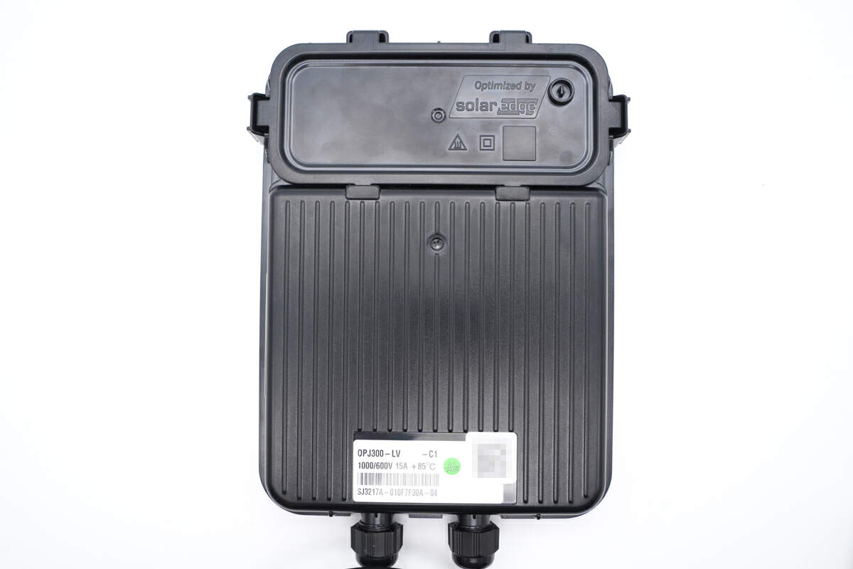
Those stripes on the plastic case can increase the heat dissipation area.
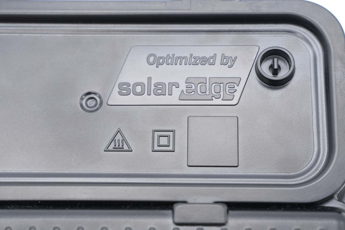
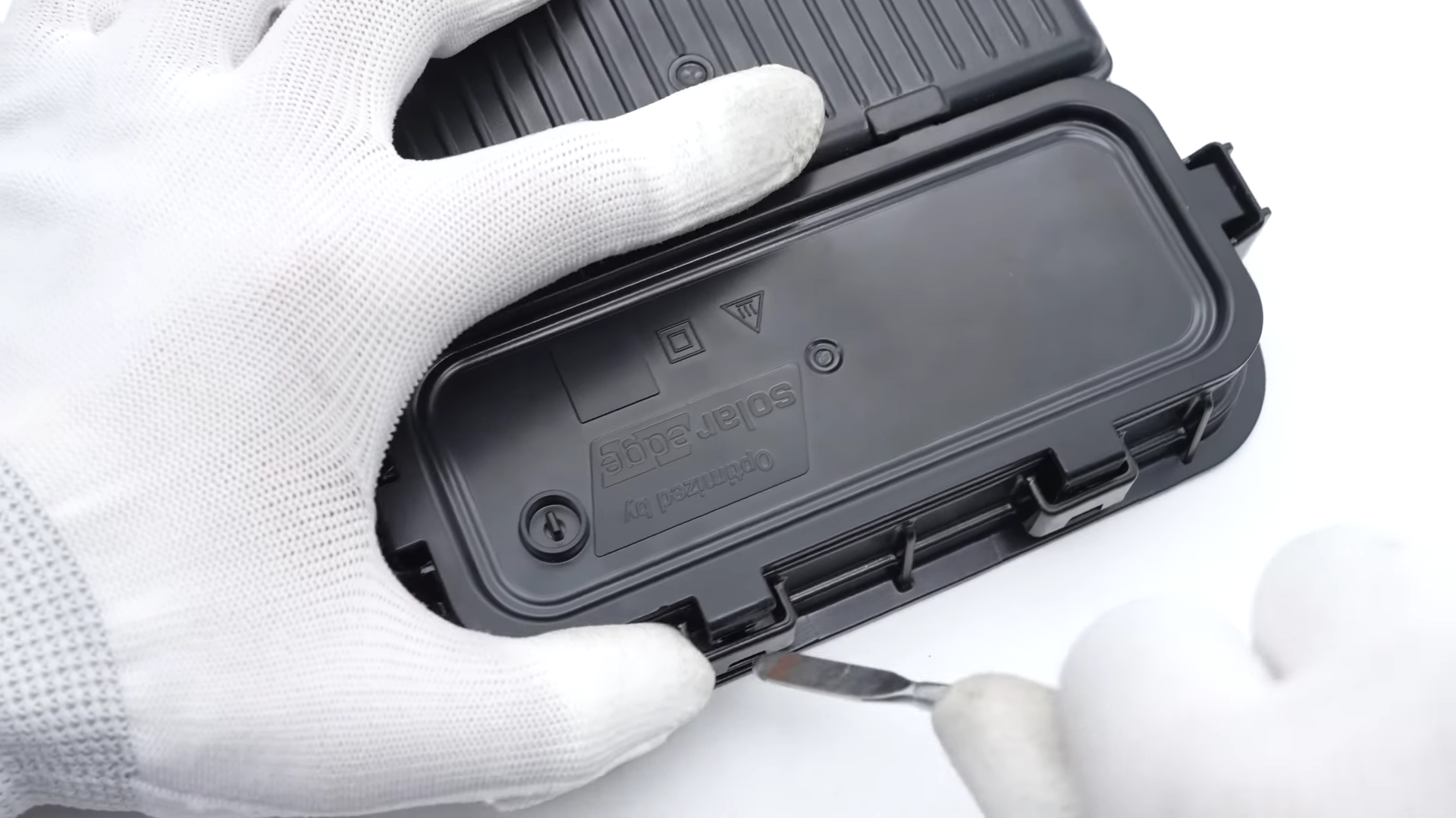
The words "Optimized by solaredge" are printed on the front cover.
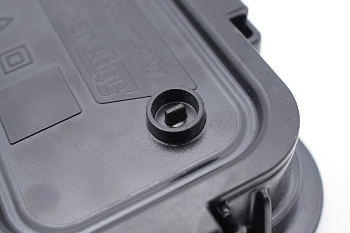
This is the opening used for ventilation.
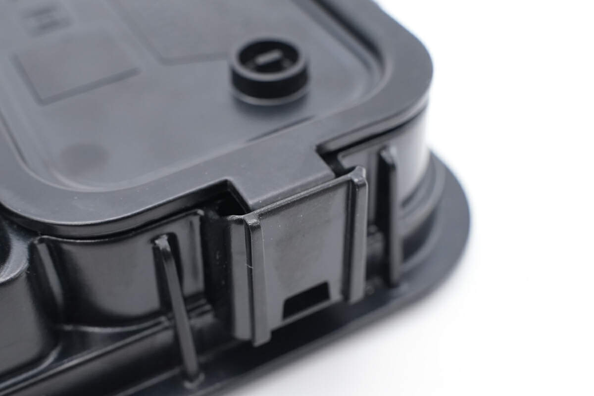
The front cover is fixed with plastic clips.
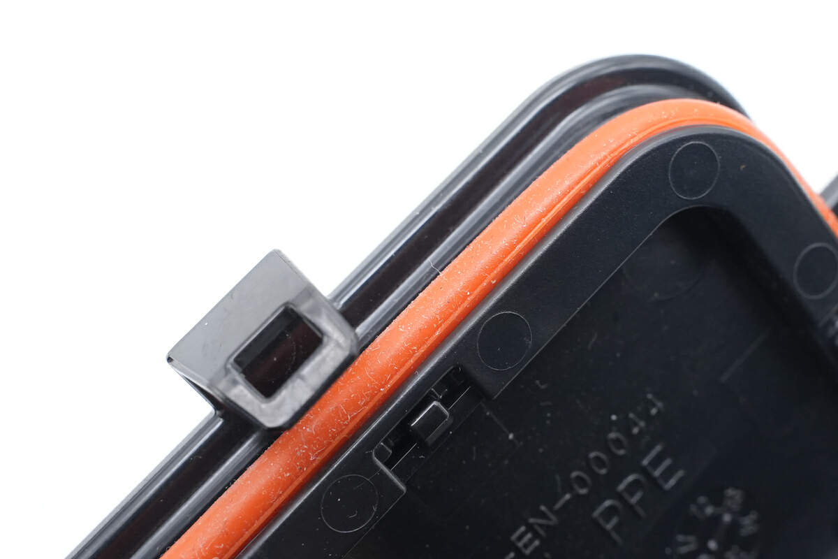
And the orange rubber seal is used for dust and water resistance.
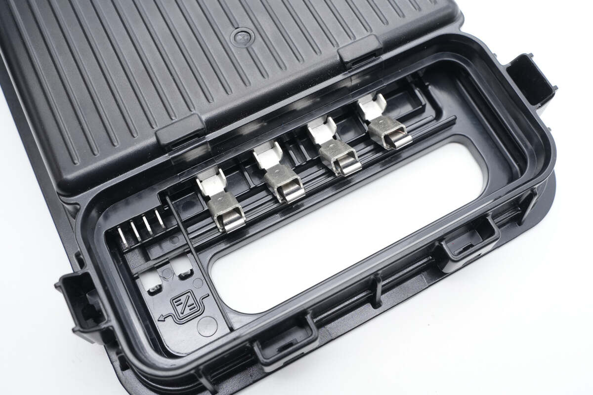
There're four ribbons on the back for output.
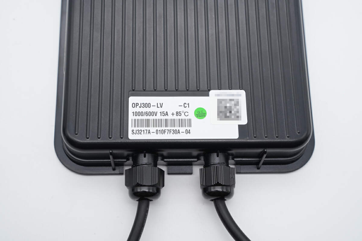
The sticker shows its model is OPJ300, you can search for more specs info on the official website.
And here is some basic info for this SolarEdge 330W Power Optimizer Module.
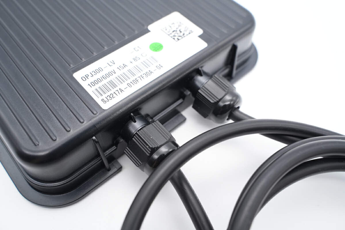
Two input cables are connected to the positive and negative side. The junction is protected by a rotatable plastic nut.
The “+” symbol means it’s a positive cable.
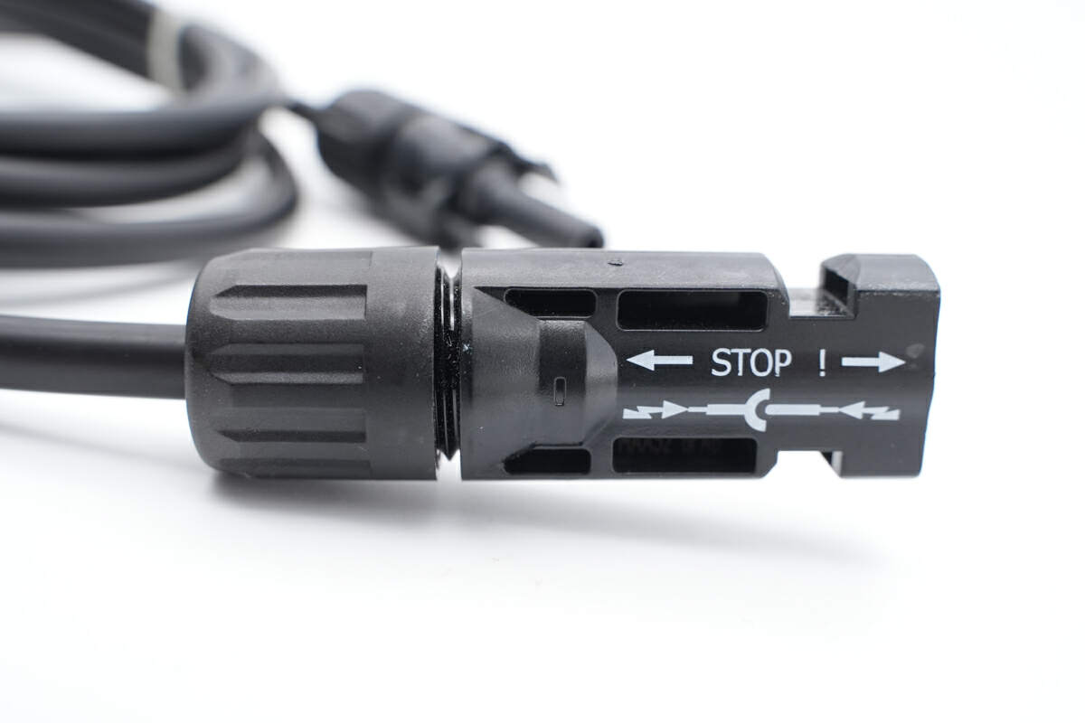
And the “-” symbol means it’s a negative cable.
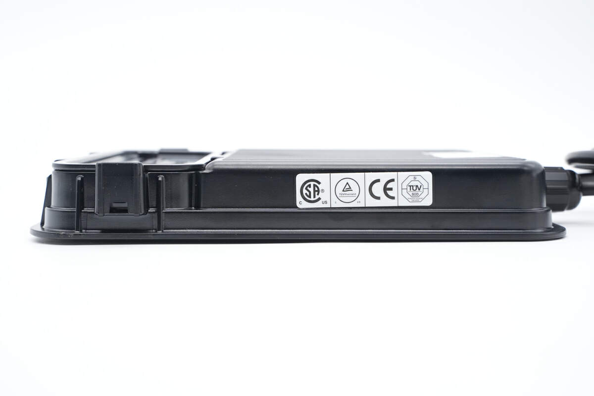
There is a product certification sticker on the side, which shows it has passed CE, TUV and other certifications.
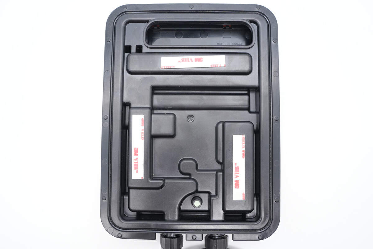
Three 3M double-sided foam tapes are pasted on the back for fixing in different places.
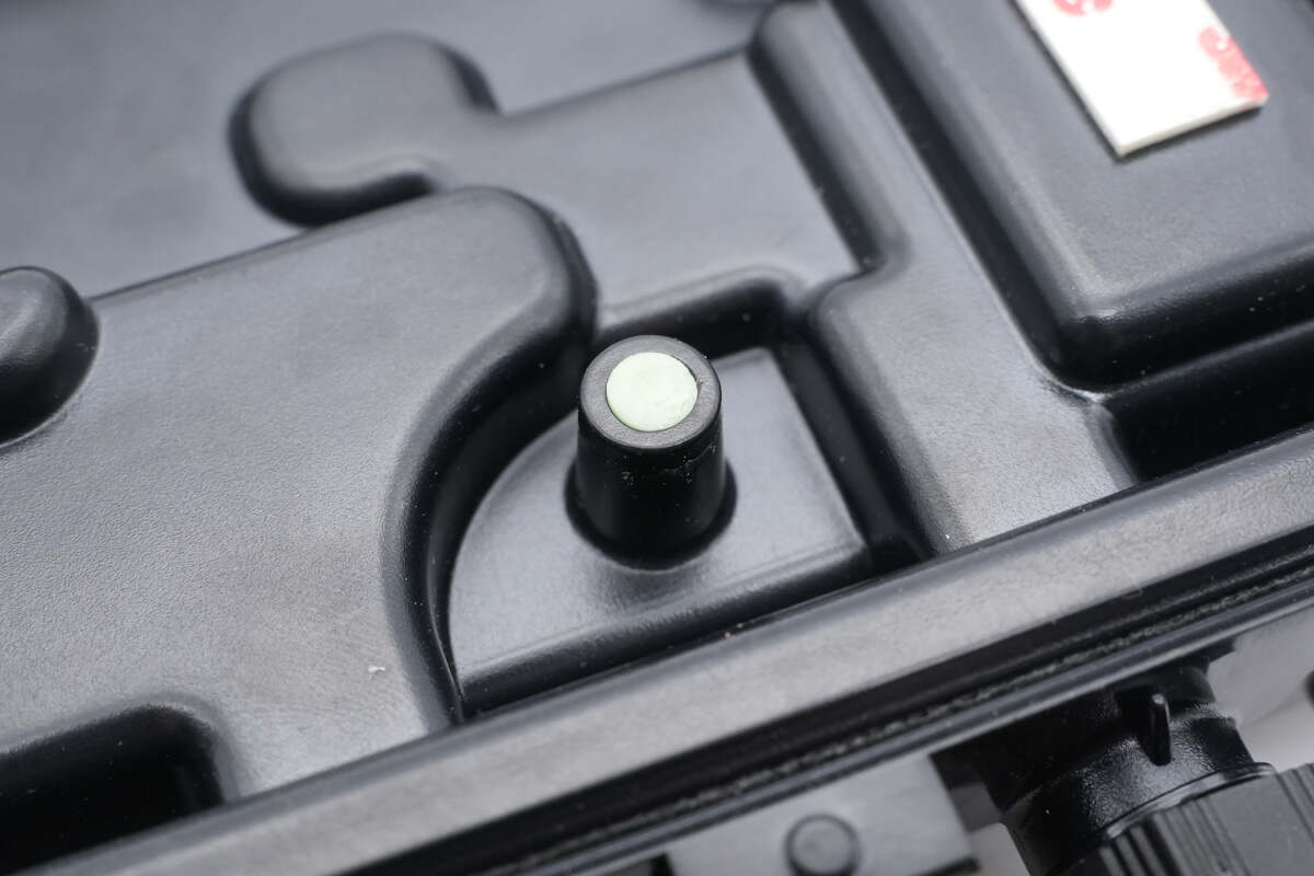
This is the opening with the internal potting filled with thermal compound.
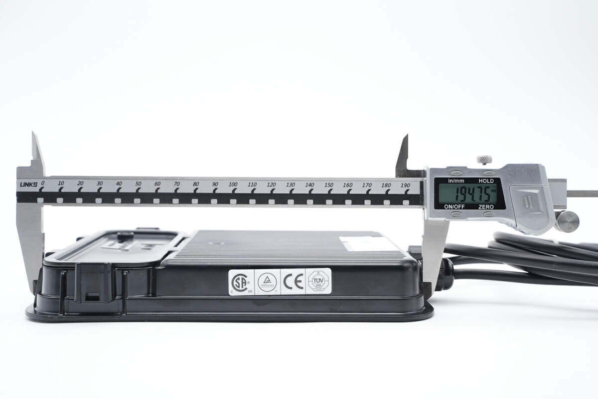
The length of this power optimizer module is about 194.8mm (7.67 inches).
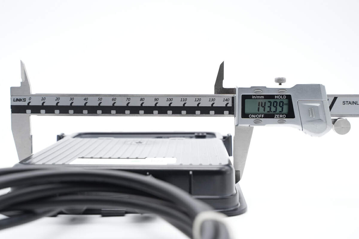
The width is about 144mm (5.67 inches).
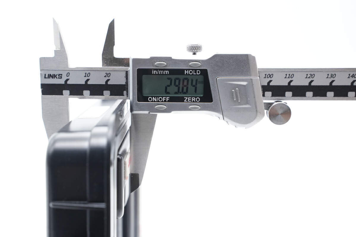
And the height is about 29.8mm (1.17 inches).
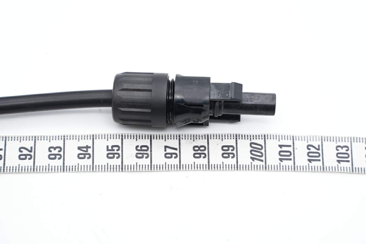
The length of the positive cable is approximately 1m (3’ 3.37”).
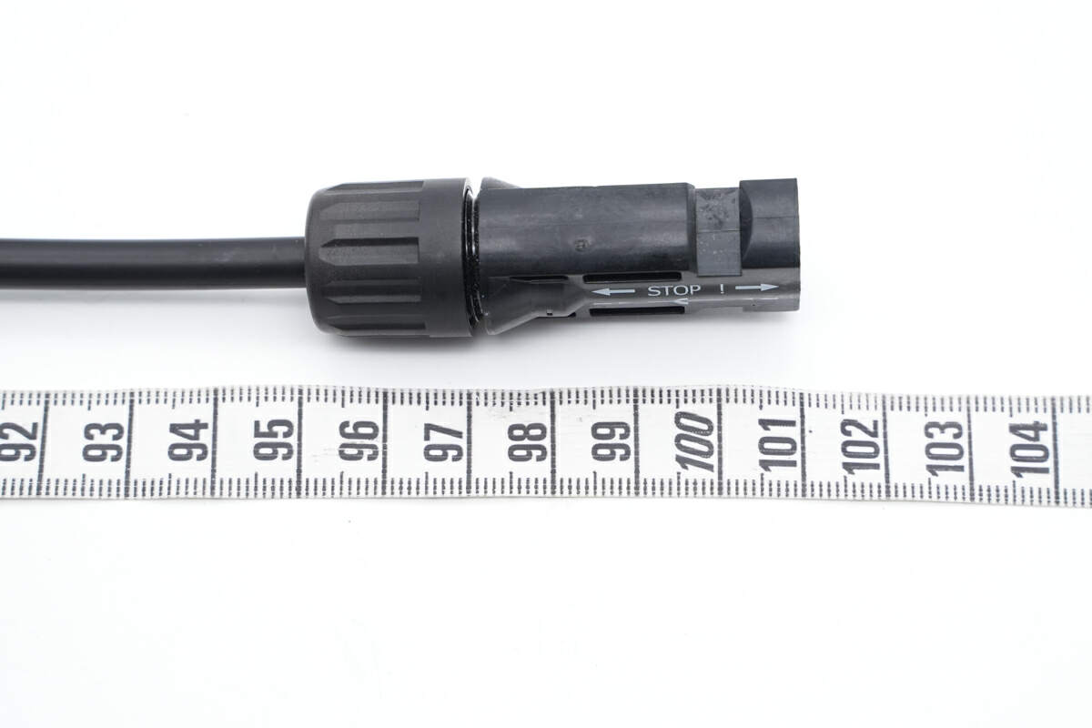
So is the negative one.
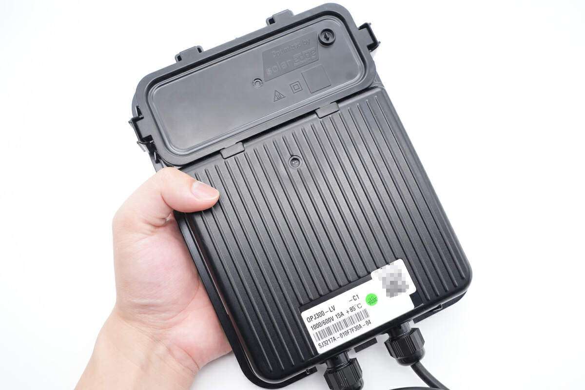
This is how it looks like on my hand.
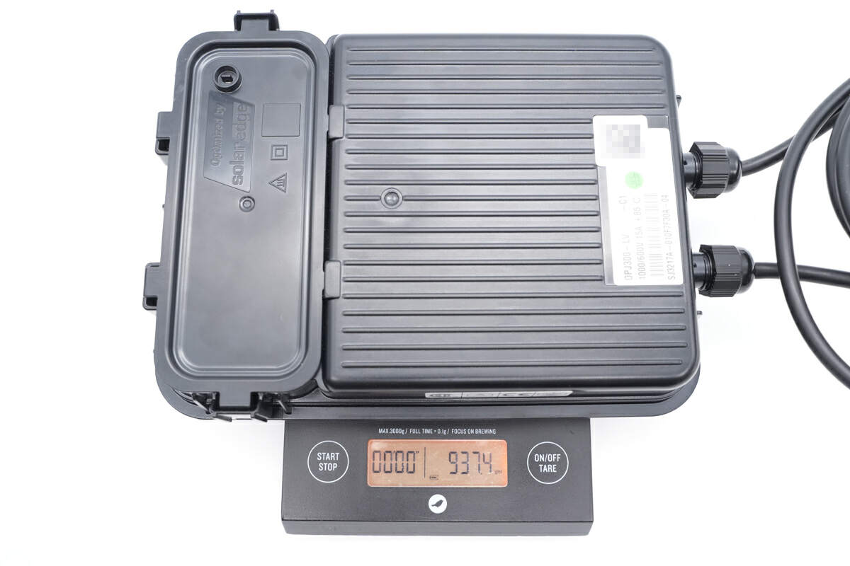
And the weight is about 937.5g (33 oz).
Teardown
Now that we have completed our unboxing and testing of this power optimizer module, it's time to take apart the device and examine its internal components and structure.
First, remove the top cover above four ribbons.
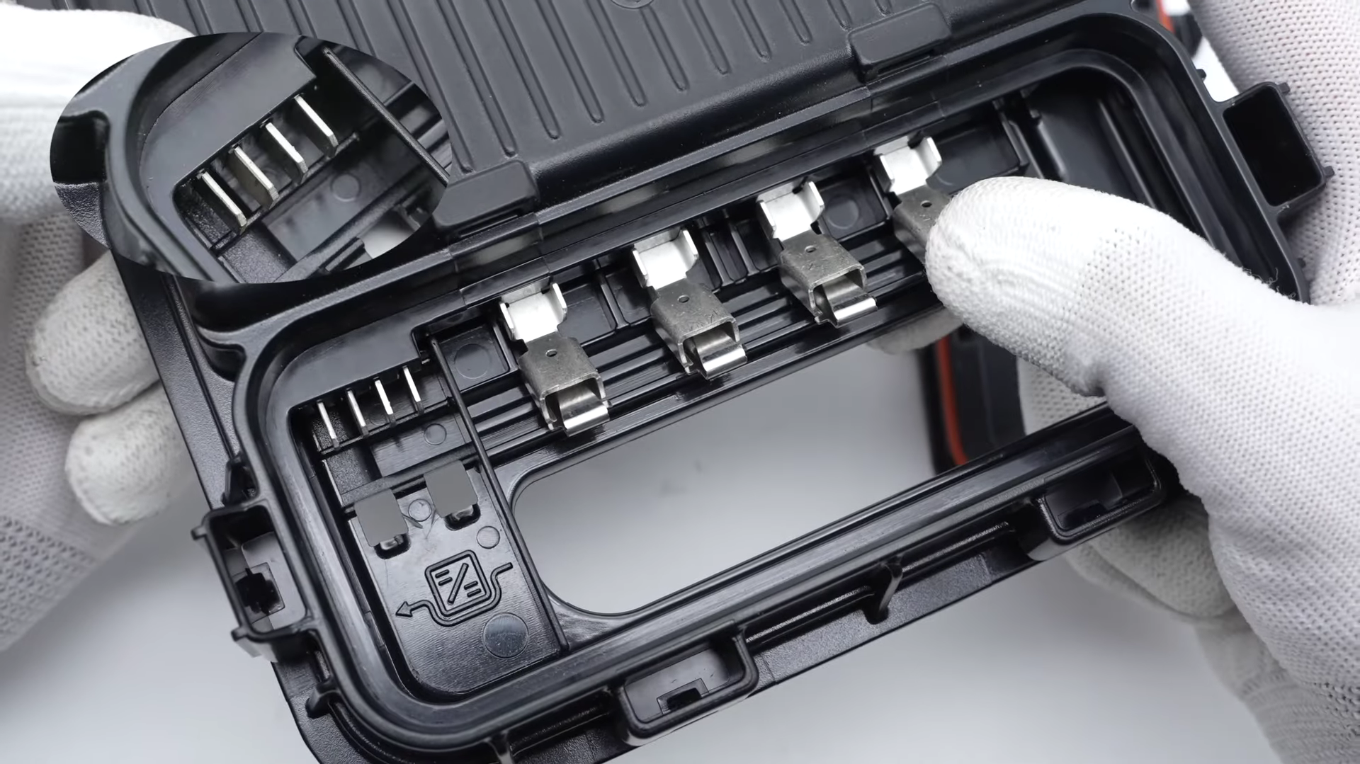
It can switch between pass-through mode and optimization mode.
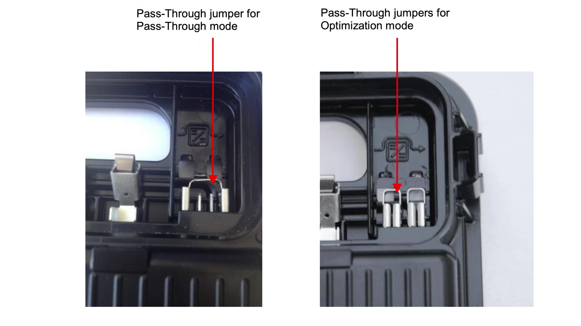
And this is how it looks like on my pass-through mode and optimization mode.
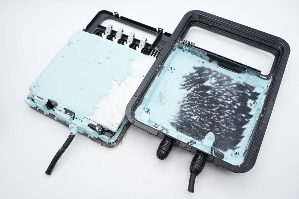
And then, use the spudger to pry along the gap and remove the back cover.
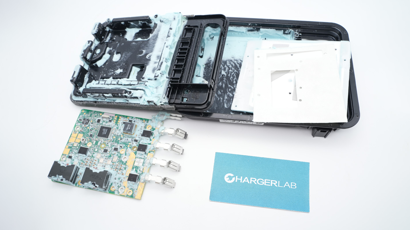
What impressed us the most is that the internal module is filled with light green potting compound.
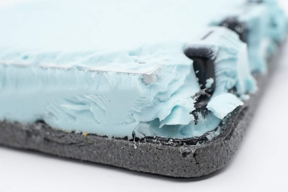
An aluminum plate is fixed inside the potting compound to enhance heat dissipation.
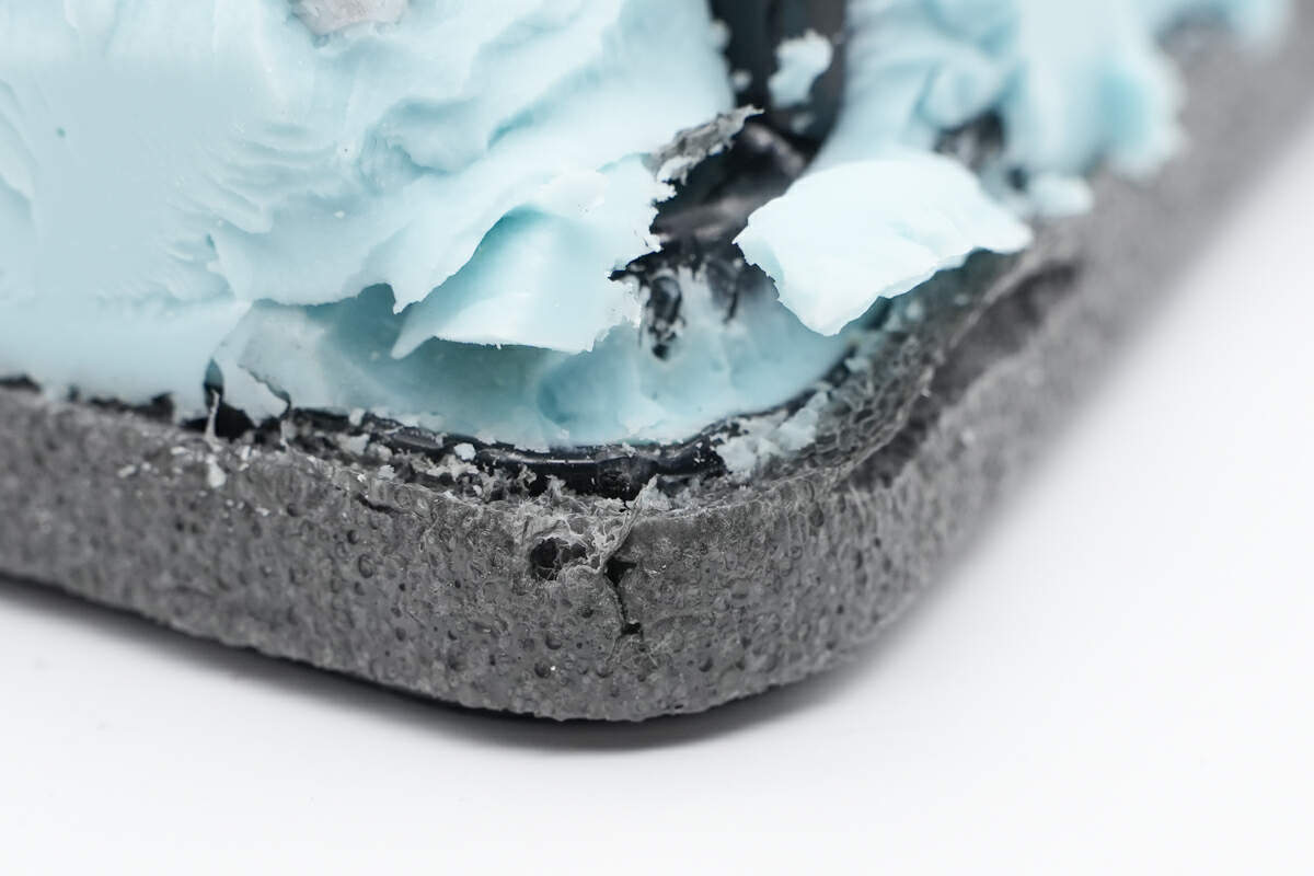
And there’s a circle of foam around the edge of the bottom case for sealing.
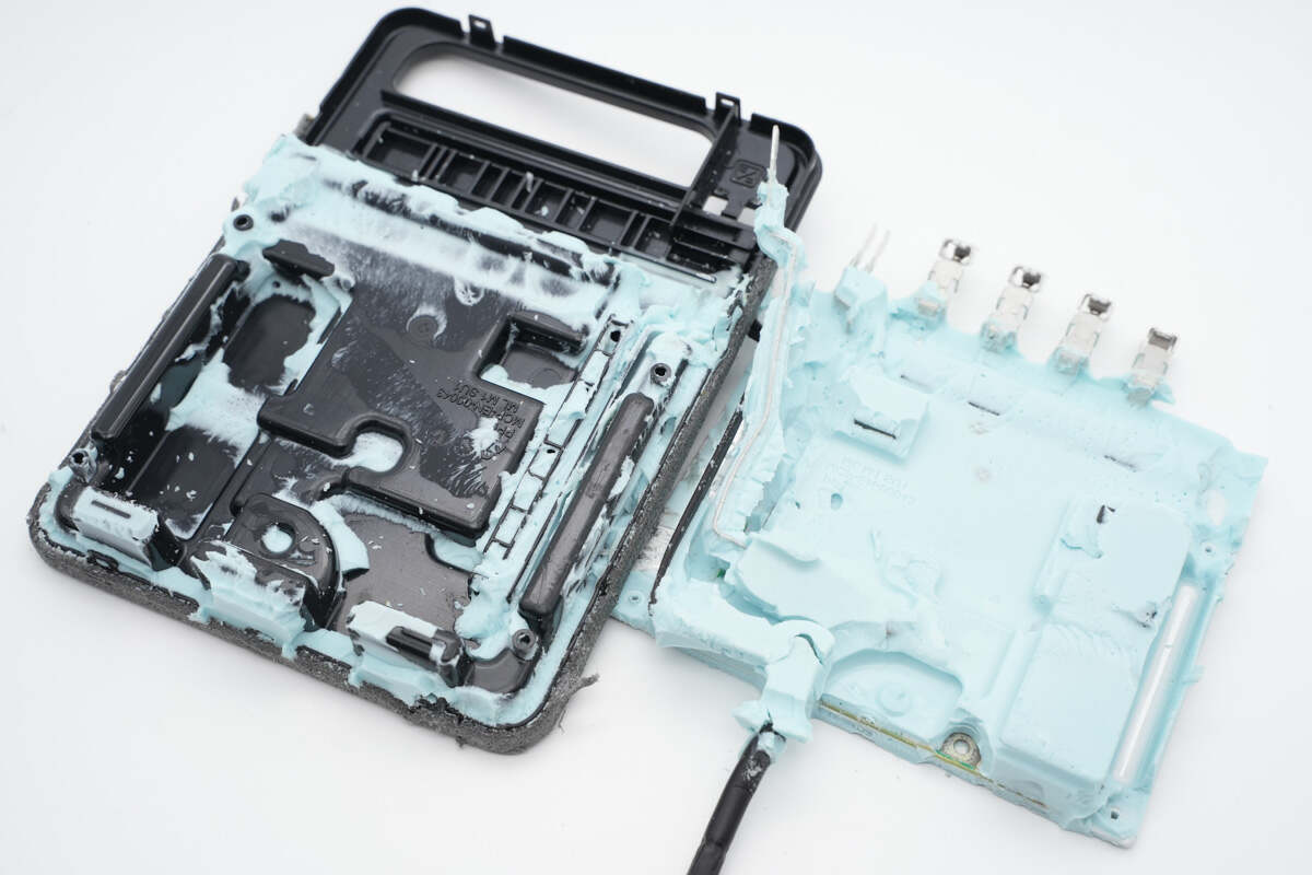
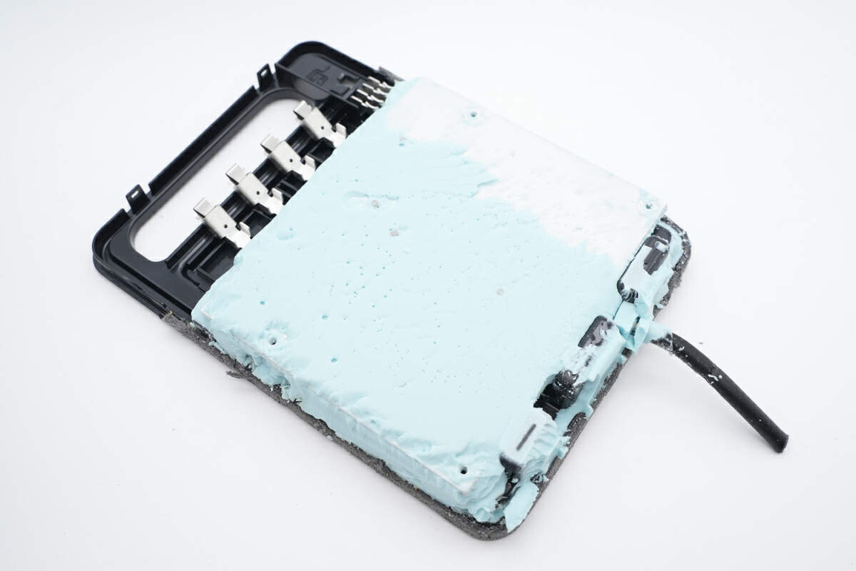
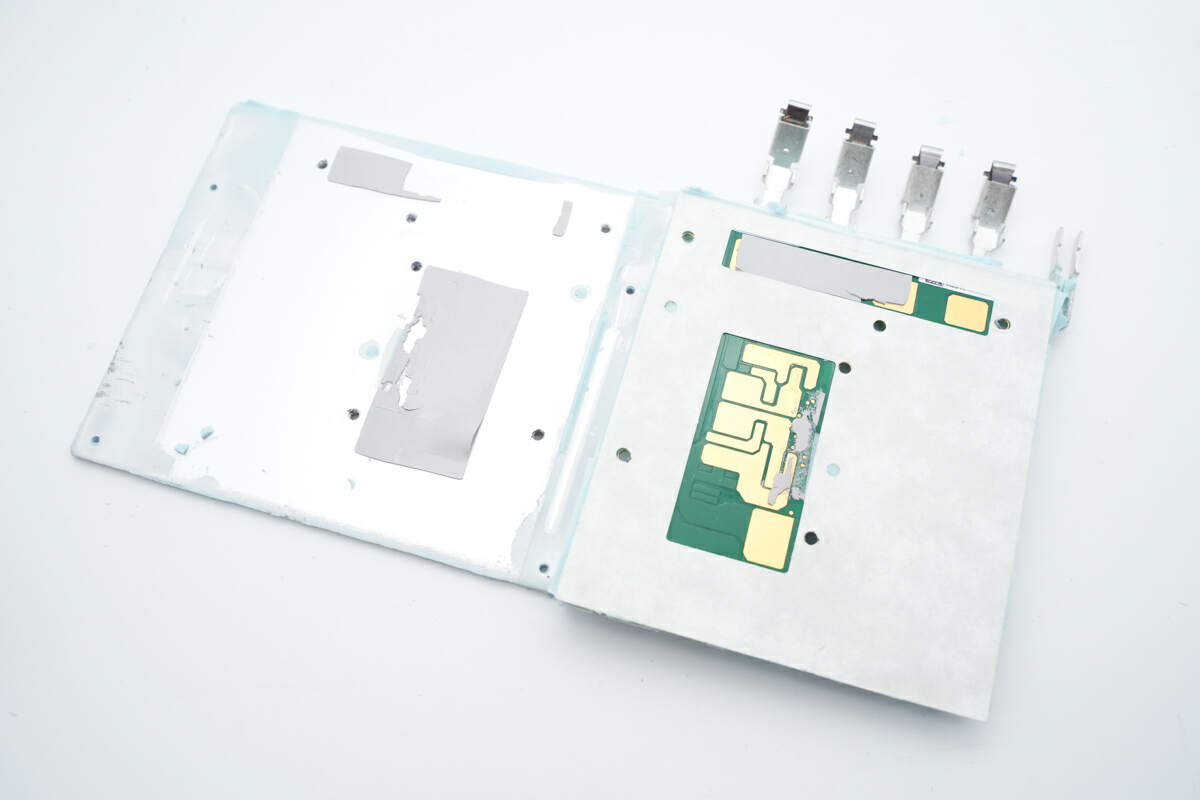
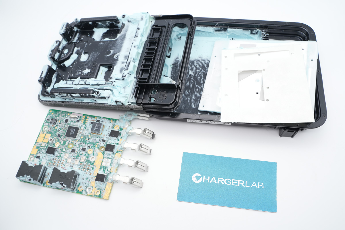
Take out the entire PCBA module, the other side is also covered with light green potting compound.
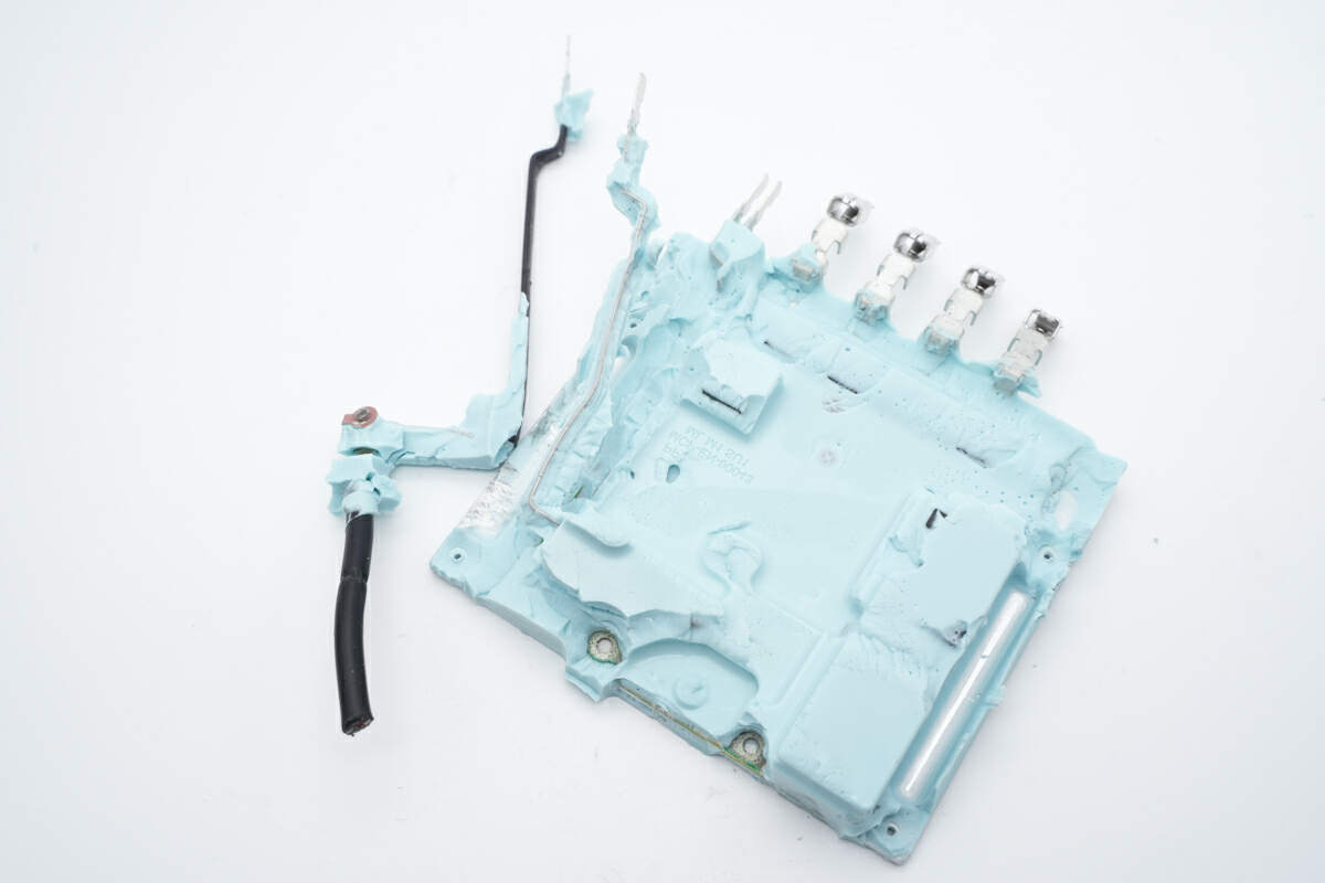
Here is the input cable.
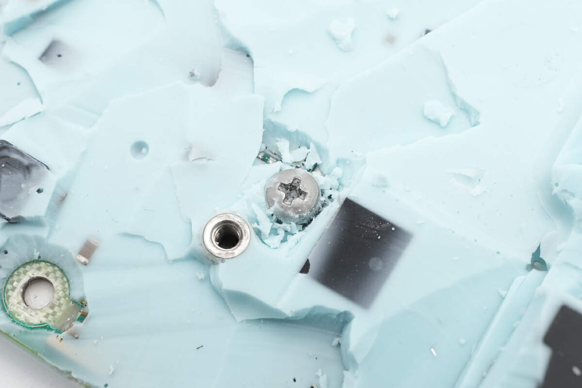
Hidden under the potting compound are the fixing screws for the aluminum plate we just mentioned.
Remove all the fixing screws and take out this thick aluminum plate, which can greatly improve the heat dissipation performance.
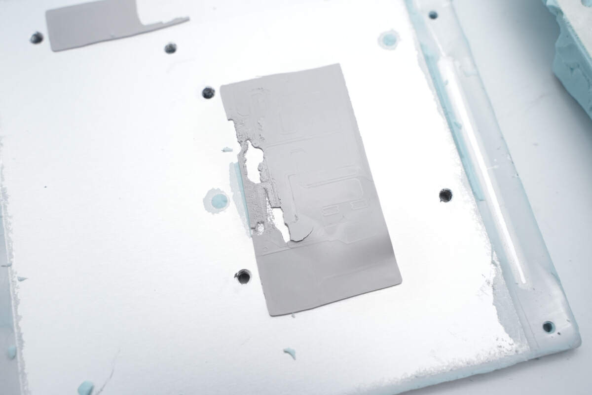
There are thermal pads on the aluminum plate that make contact with the PCB.
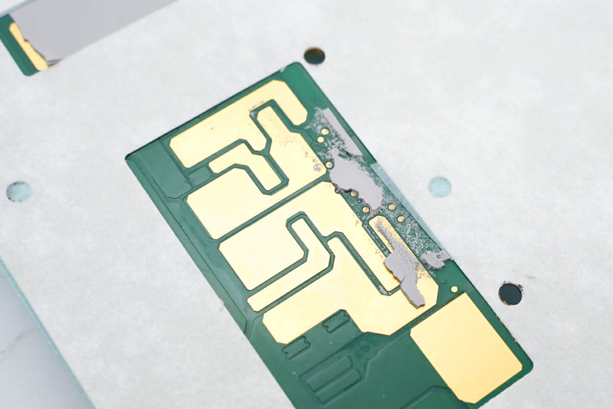
There is exposed copper in the heat-generating area of the PCB for enhanced heat dissipation.
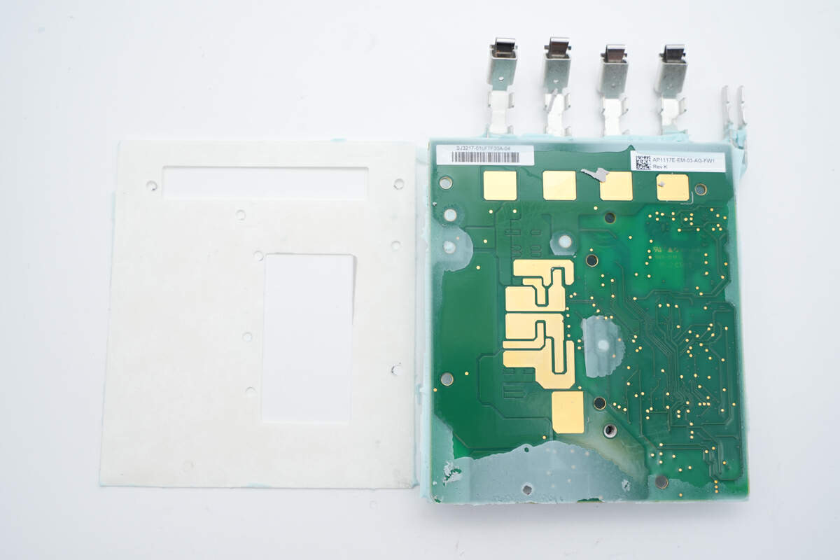
An insulating layer is between the aluminum plate and PCB.
It took us really long to get it cleaned up. Then, we’ll introduce every single component.
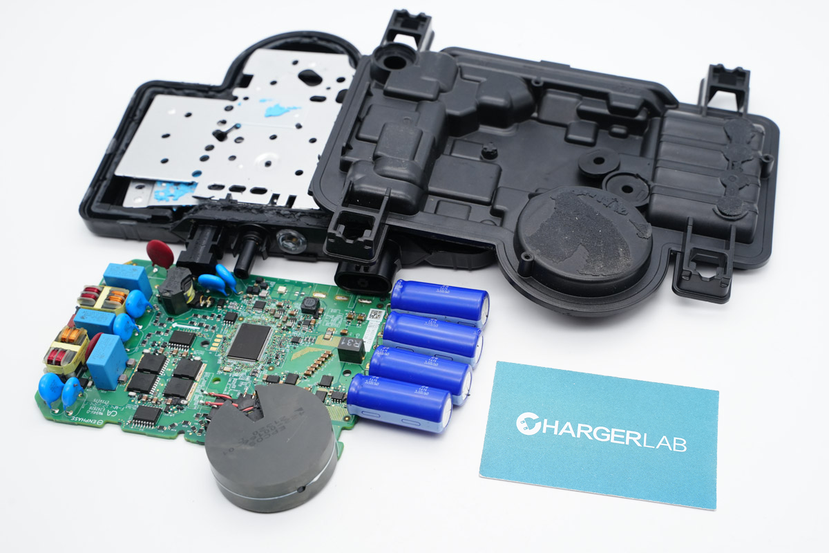
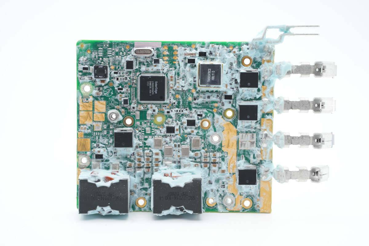
First, let's take a look at the front side of the PCBA module. At the bottom, there are two inductors wound with copper strips. On the right side, there is a synchronous buck-boost MOSFET. Above the PCBA, the master control chip and the buck module are soldered. On the right side, you can find the output ends.
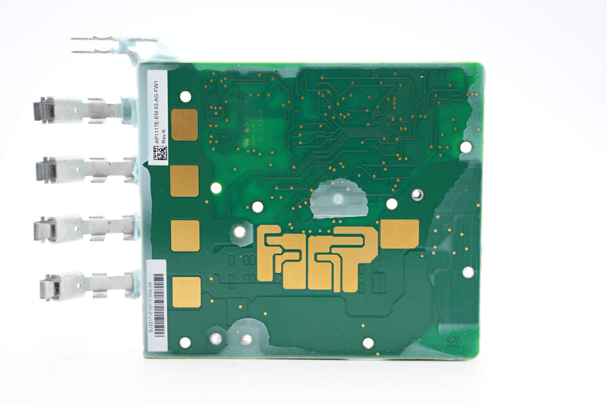
Those gold-plated pads on the back can also enhance heat dissipation.
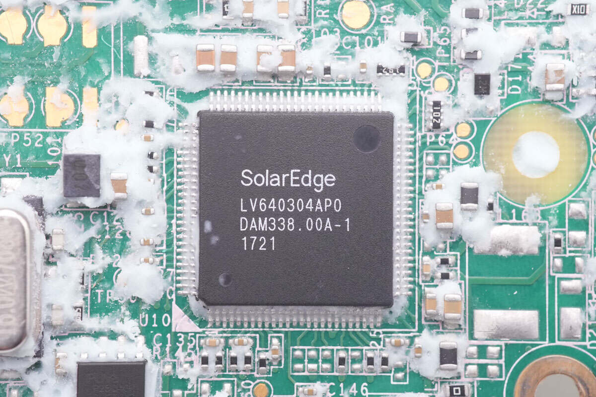
The master control chip marked with LV640304AP0 is from SolarEdge, used for communication and protection. It can output the signal of synchronous buck-boost driver, in which the synchronous buck-boost is driven by two half-bridge drivers.
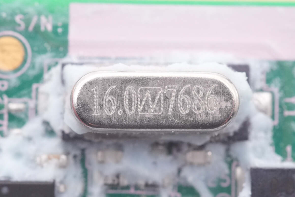
This is the external 16.0MHz crystal oscillator of the master control chip.
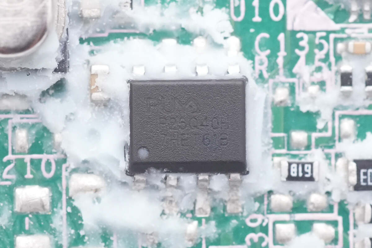
The memory is from Puya, model P25Q40H, which is used to store firmware info.
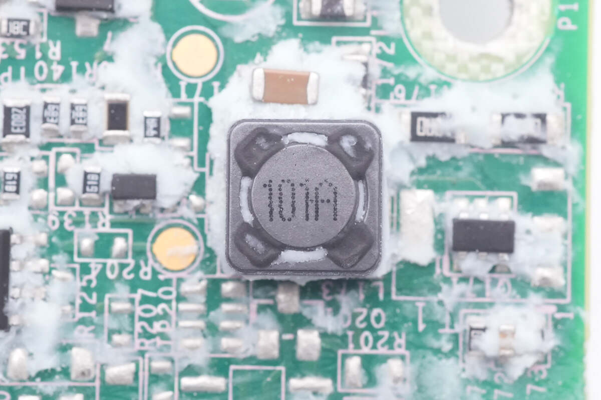
This is an external buck inductor.
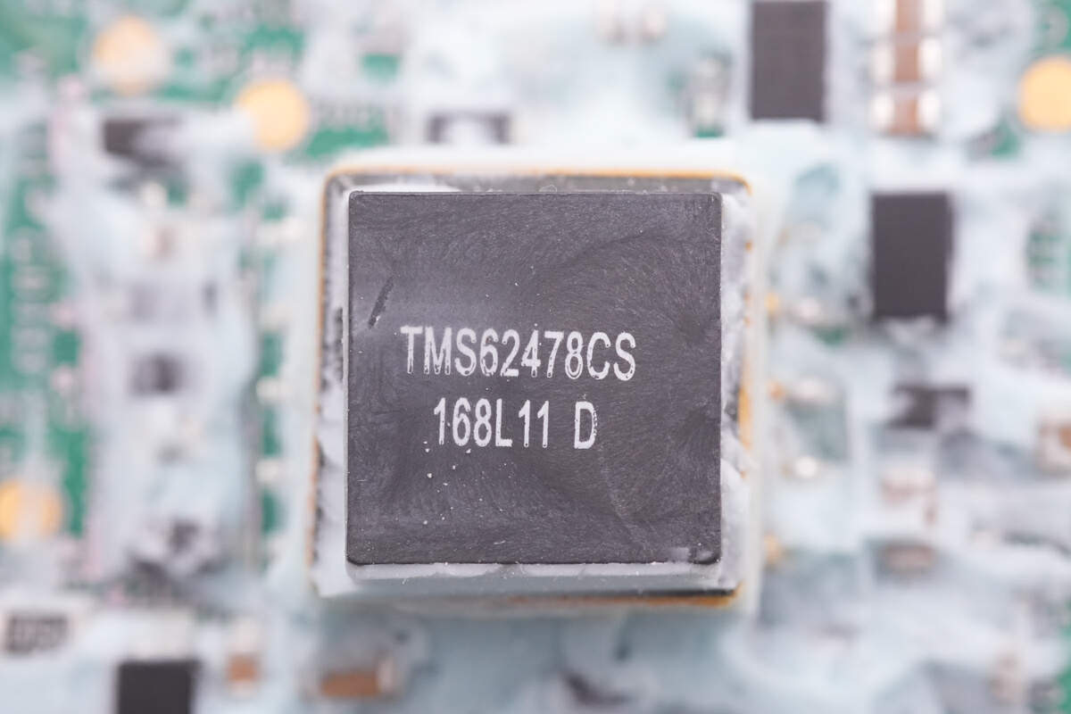
And here is a buck module that powers the master control chip.
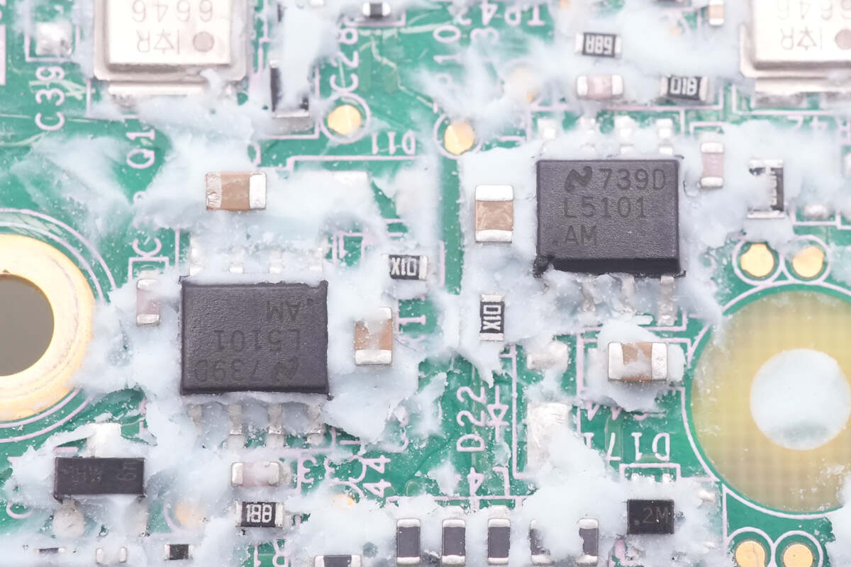
Those two half-bridge drivers are from TI, model LM5101AM, which are used to drive the synchronous buck-boost MOSFETs. It can support up to 3A, and withstand voltage is 100V.
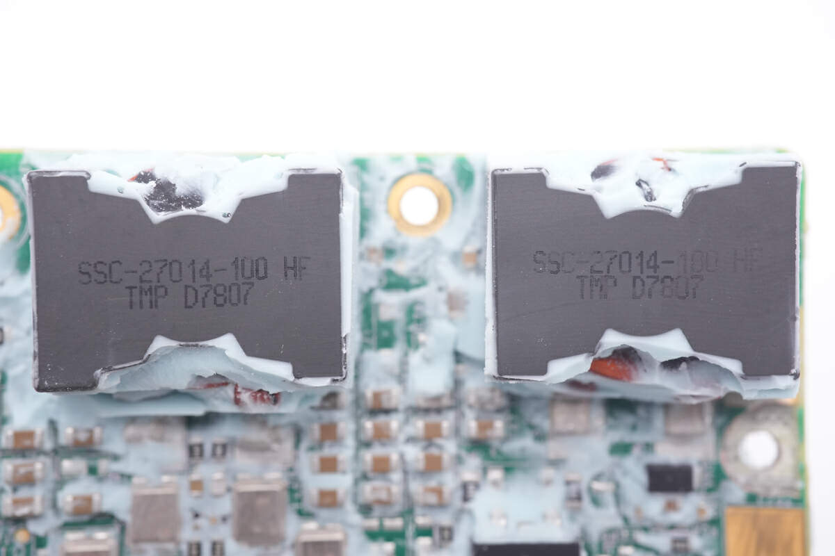
Here are two inductors, wound with copper foil.
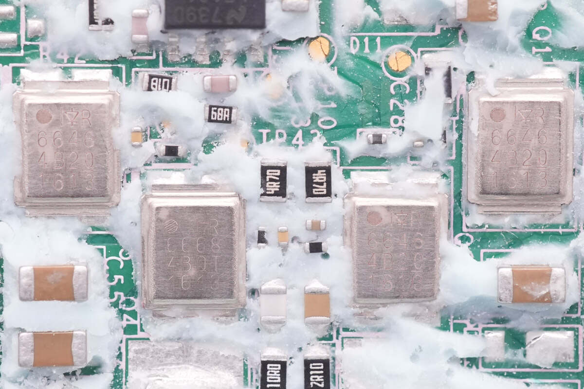
Those four synchronous buck-boost MOSFETs are all from Infineon, three of which are IRF6646, NMOS, withstand voltage is 80V, and resistance is 7.6mΩ. There is also a IRF6668, NMOS, with a withstand voltage of 80V and a resistance of 12mΩ.
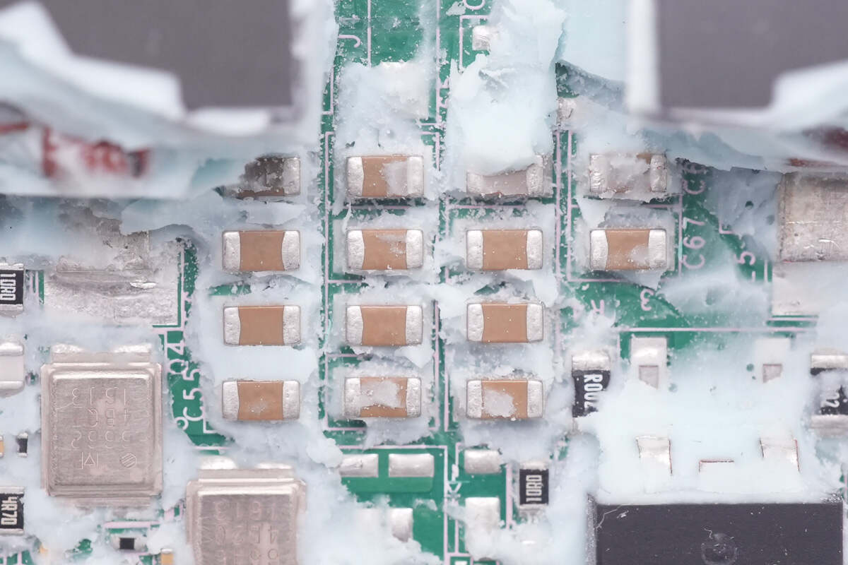
Those are some MLCC filter capacitors.
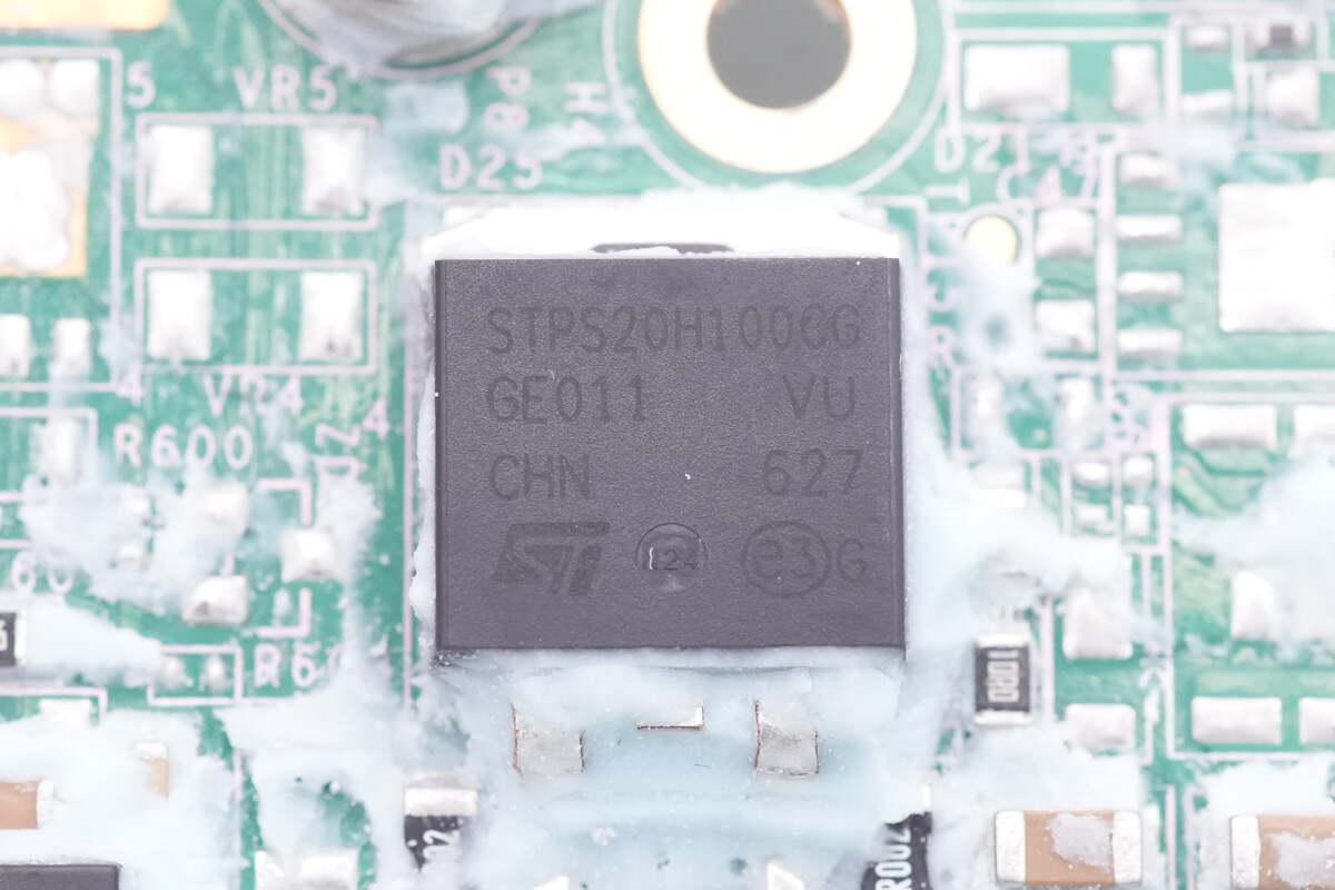
The Schottky diode at the input end is from STMicroelectronics, model STPS20H100CG, which is used for anti-reverse protection. Withstand voltage is 100V and the current is 20A.
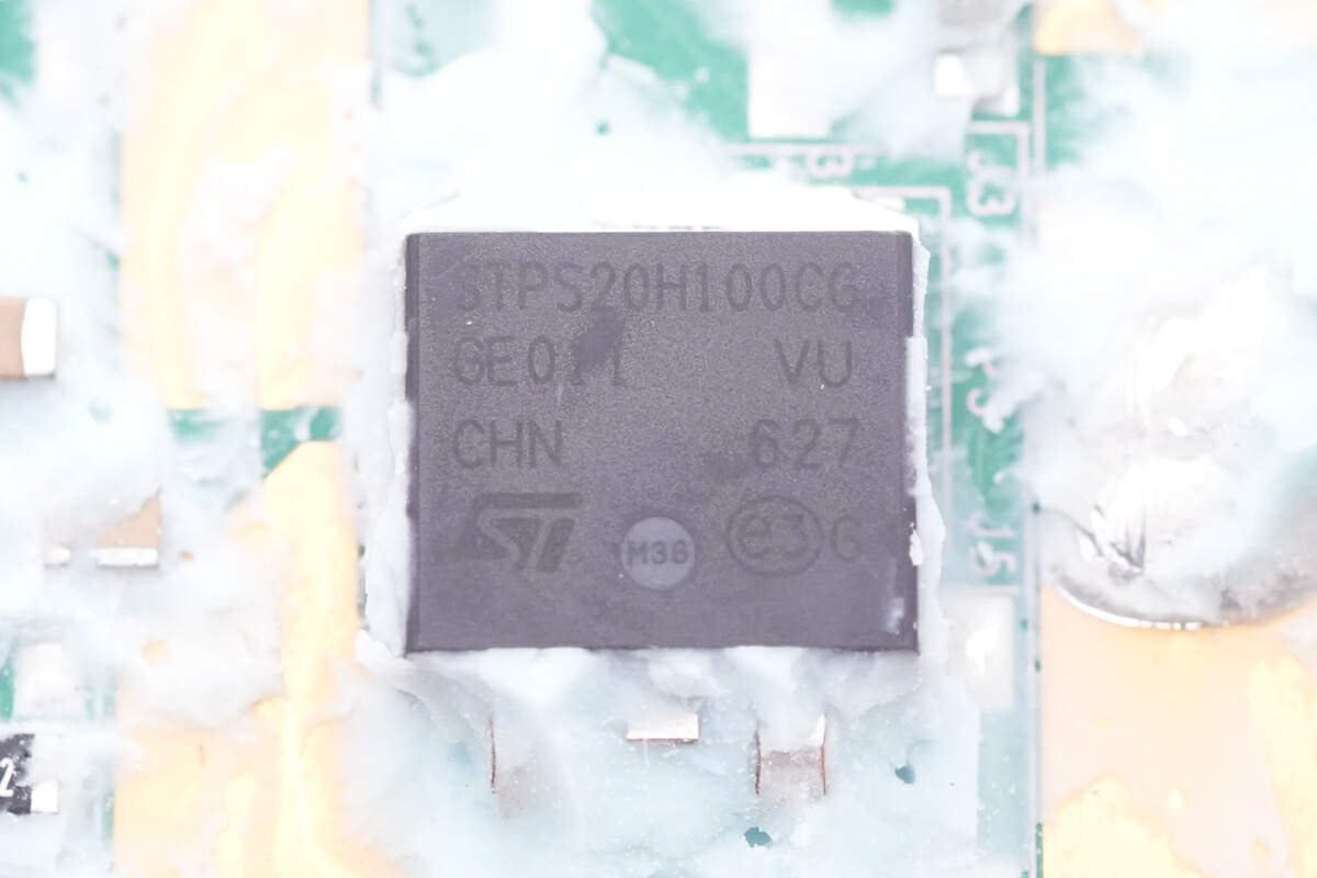
Also, three identical Schottky diodes are soldered next to three ribbons. Here is one of them.
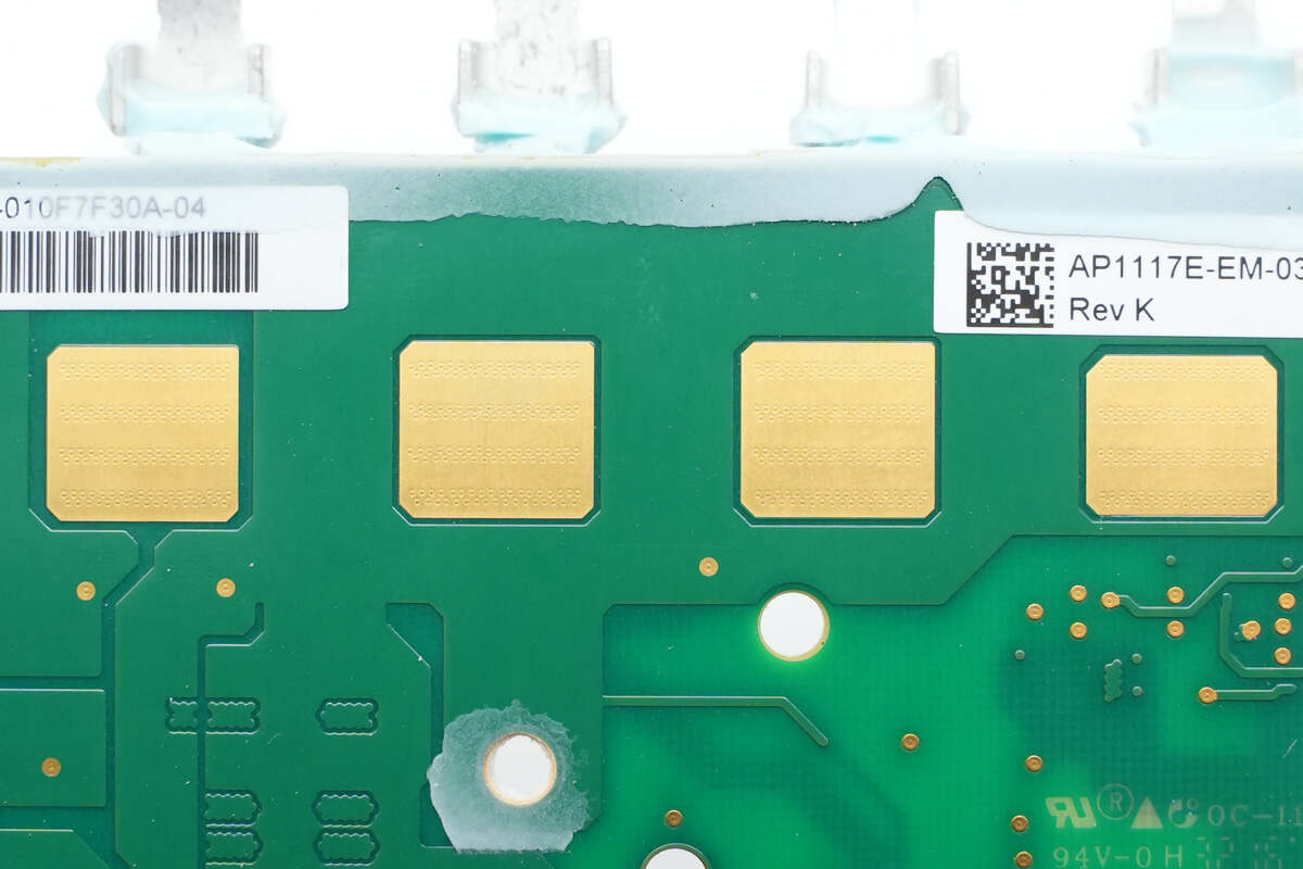
If we get closer, we will find dense holes on the gold-plated pads to speed up heat dissipation.
One last look at all the components of this SolarEdge 330W Power Optimizer Module.
Summary of ChargerLAB
The SolarEdge 330W Power Optimizer Module comes with a 1m (3’ 3.37”) long input cable and performs voltage buck and boost conversion of the solar panel output. This optimization enables the solar panels to achieve their maximum power output, thereby enhancing the overall energy generation and optimizing the solar power system's efficiency. With an output power of 330W, this optimizer supports input voltage ranges of 5-55V/12.5A and output voltage ranges of 5-60V/15A.
To sum it up, by delving into its components and structure, we've uncovered the meticulous design and engineering behind this device. From the attention-grabbing appearance, with heat dissipation features and vibrant stripes, to the practicality of embedded functionality and wide input voltage range, the SolarEdge optimizer module stands out as a great product. The use of light green potting compound, strategically placed thermal pads, and an aluminum plate for enhanced heat dissipation showcases the module's commitment to efficiency and reliability. Moreover, the presence of industry-leading components like the SolarEdge master control chip, TI half-bridge drivers, Infineon synchronous buck-boost MOSFETs, and STMicroelectronics Schottky diodes instills confidence in its performance and longevity.
Related Articles:
1. Teardown of Enphase IQ8X Microinverter (For Solar Energy)
2. Teardown of Enphase IQ7+ Microinverter (For Solar Energy)
3. Teardown of SolarEdge 330W Power Optimizer Module Embedded Solution (Video)