Introduction
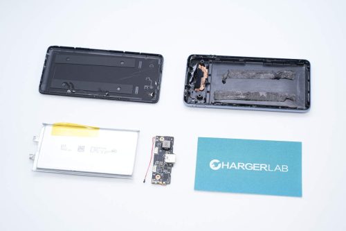
This time, ChargerLAB got a magnetic wireless power bank from SHARGE. Its case adopts a transparent design so that the internal components can be seen. It also has a cooling fan inside. It has a built-in 10000mAh battery and supports 20W wired charging and 7.5W wireless charging.
Next, we will take it apart to see its internal components and structure.
Product Appearance
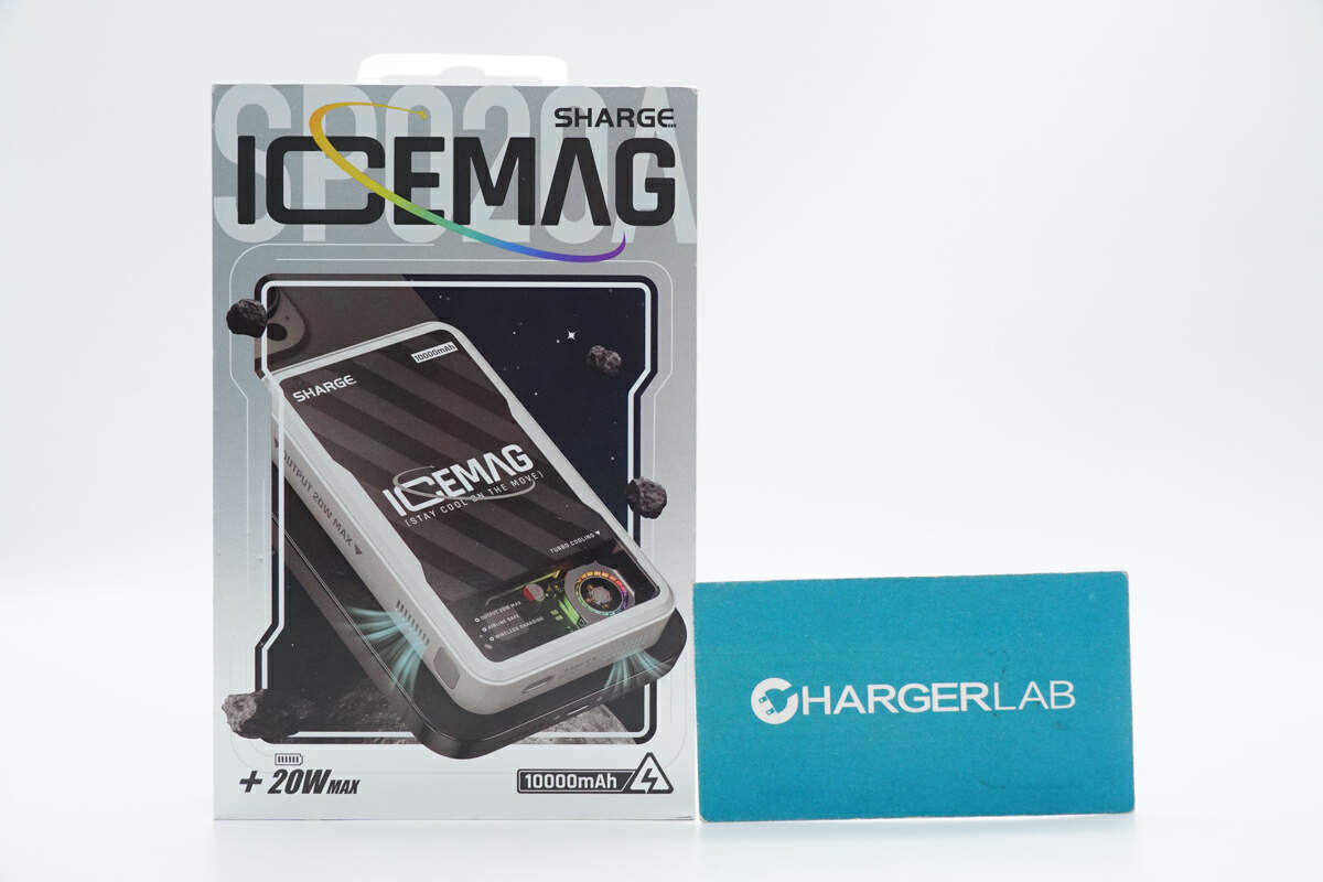
On the front of the box, there is a scene of the power bank wirelessly charging a phone. The "SHARGE" and the model of the power bank (SP020A) are printed on the top. The capacity of 10000mAh and the maximum power of 20W are also printed below.
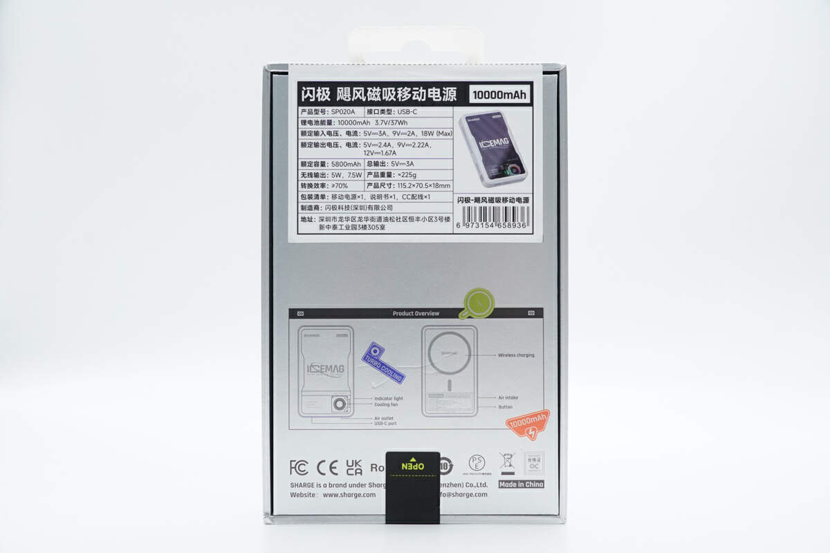
The product illustrations and certification information are printed on the back, and specs info are posted above.
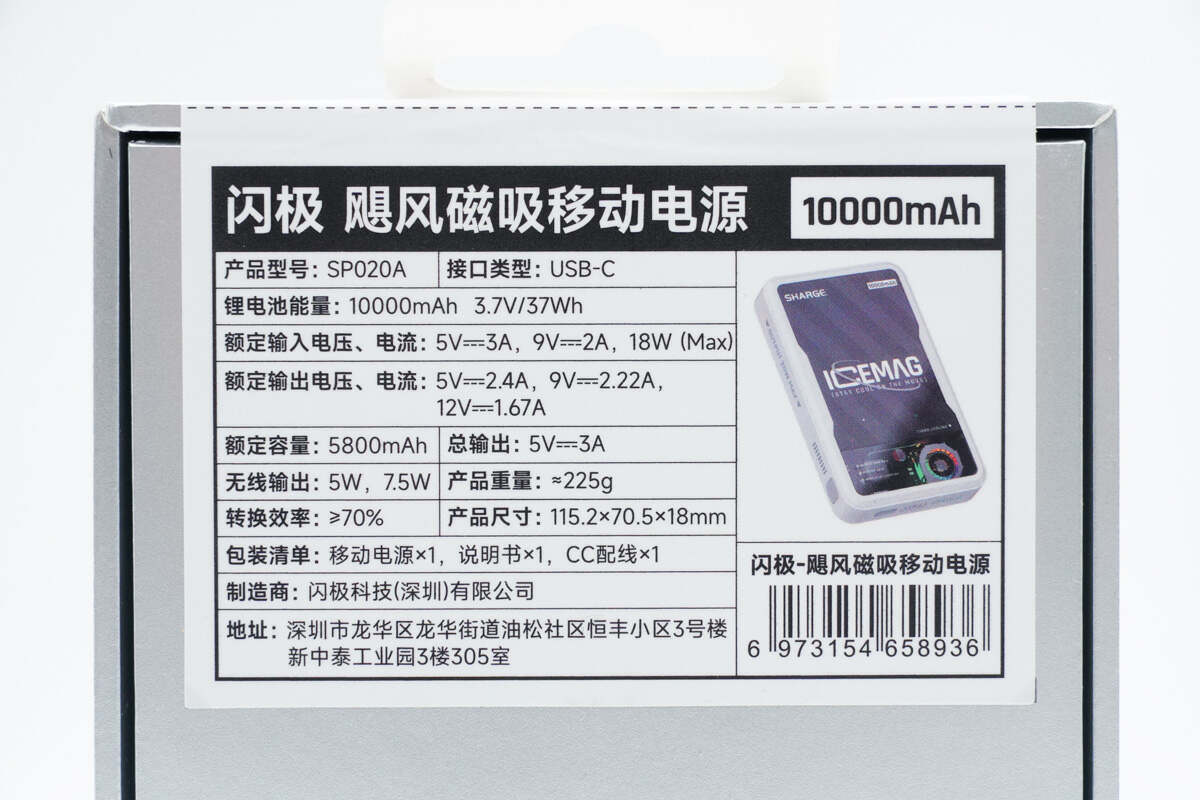
Here are the specs info, we'll talk about later.
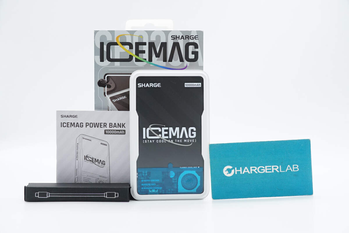
The box contains the power bank, a cable, and some documents.
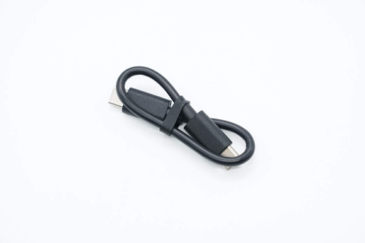
The included dual USB-C cable is short in length.
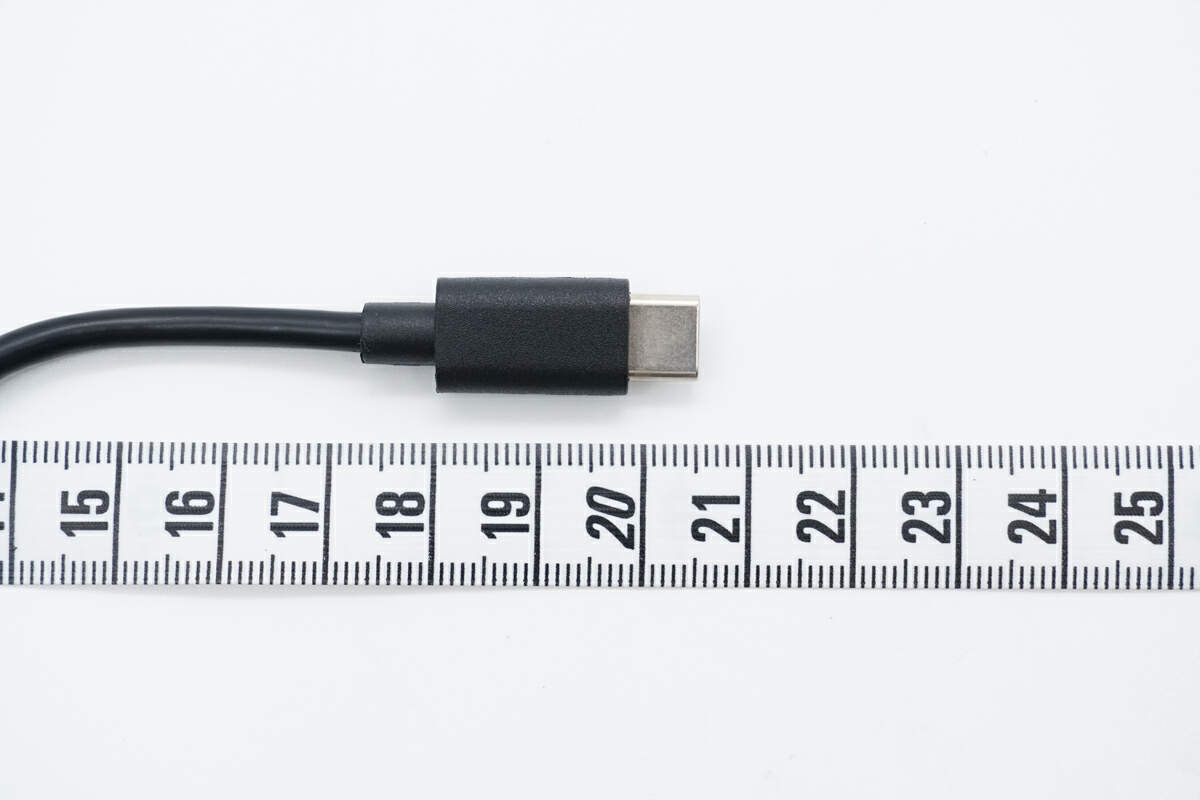
Its length is about 20.5 cm (8.1 inches).
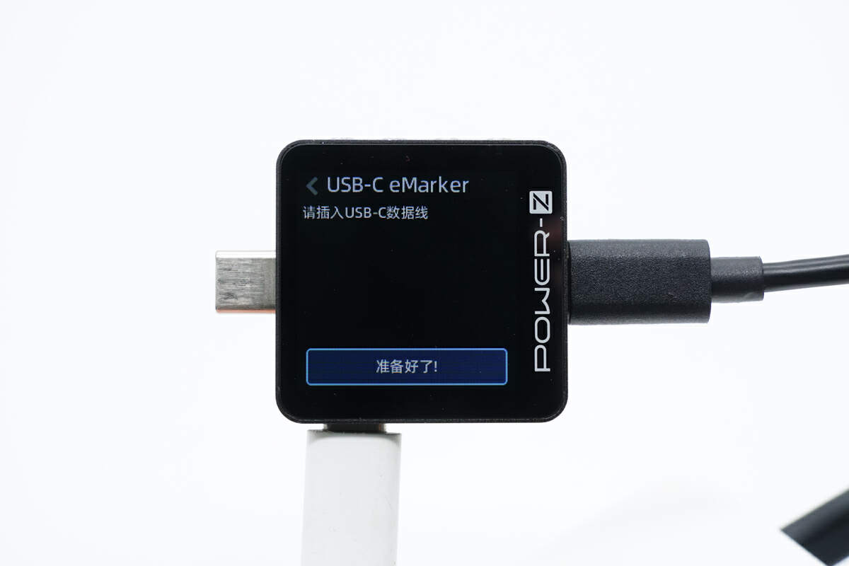
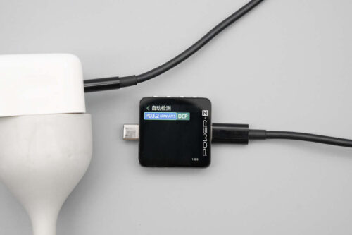
The ChargerLAB POWER-Z KM003C shows it does not have an E-Marker chip.
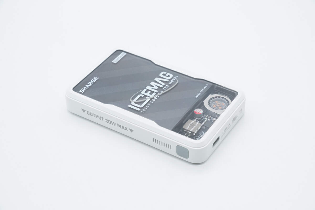
The power bank has a transparent design on the front, and the battery and PCB are visible. The plastic frame is white.
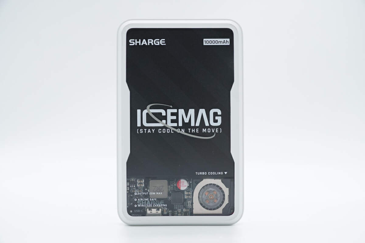
The transparent case is printed with "SHARGE", "10000mAh', and the slogan ICEMAG (STAY COOL ON THE MOVE).
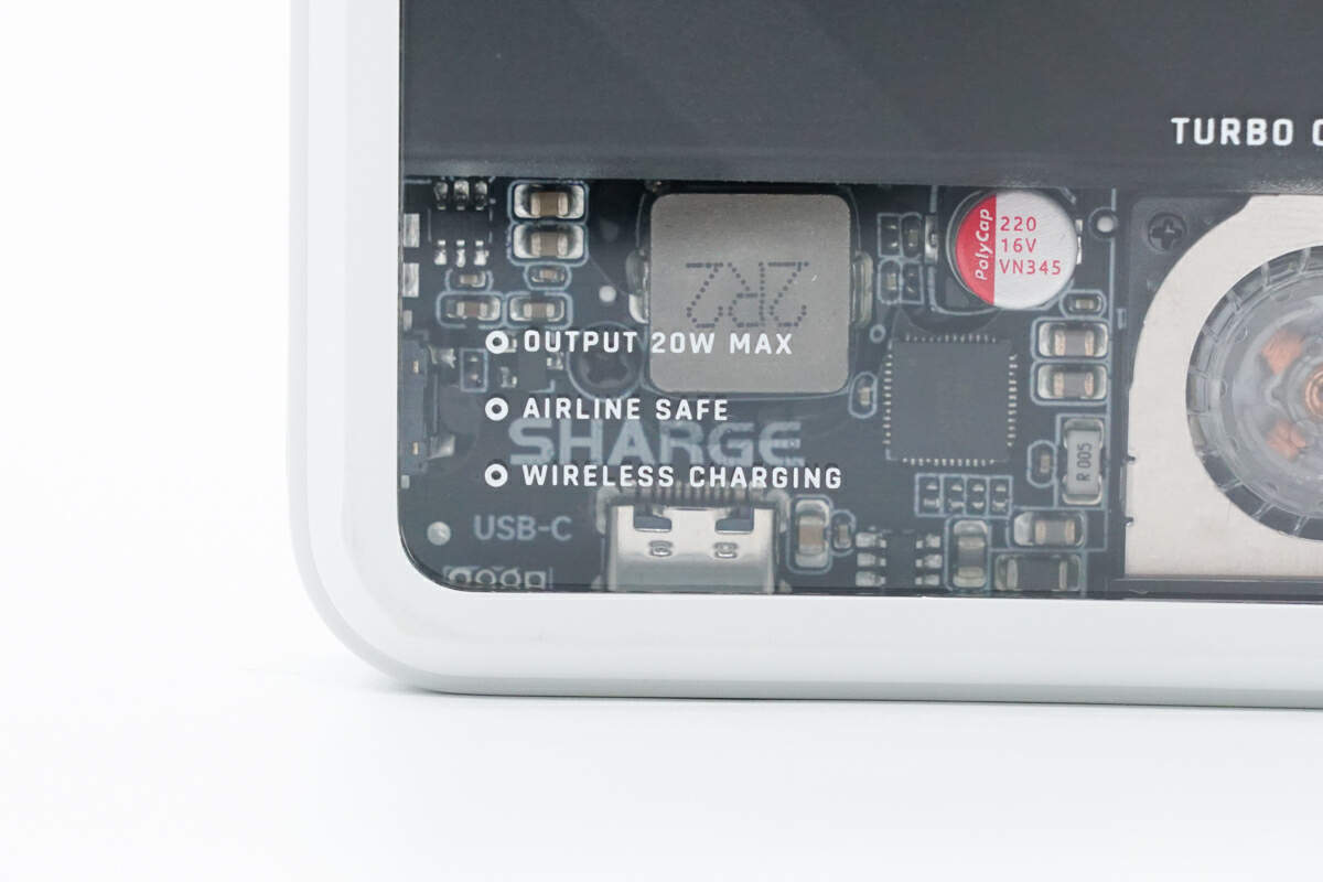
The three selling points of OUTPUT 20W MAX, AIRLINE SAFE, and WIRELESS CHARGING are printed below.
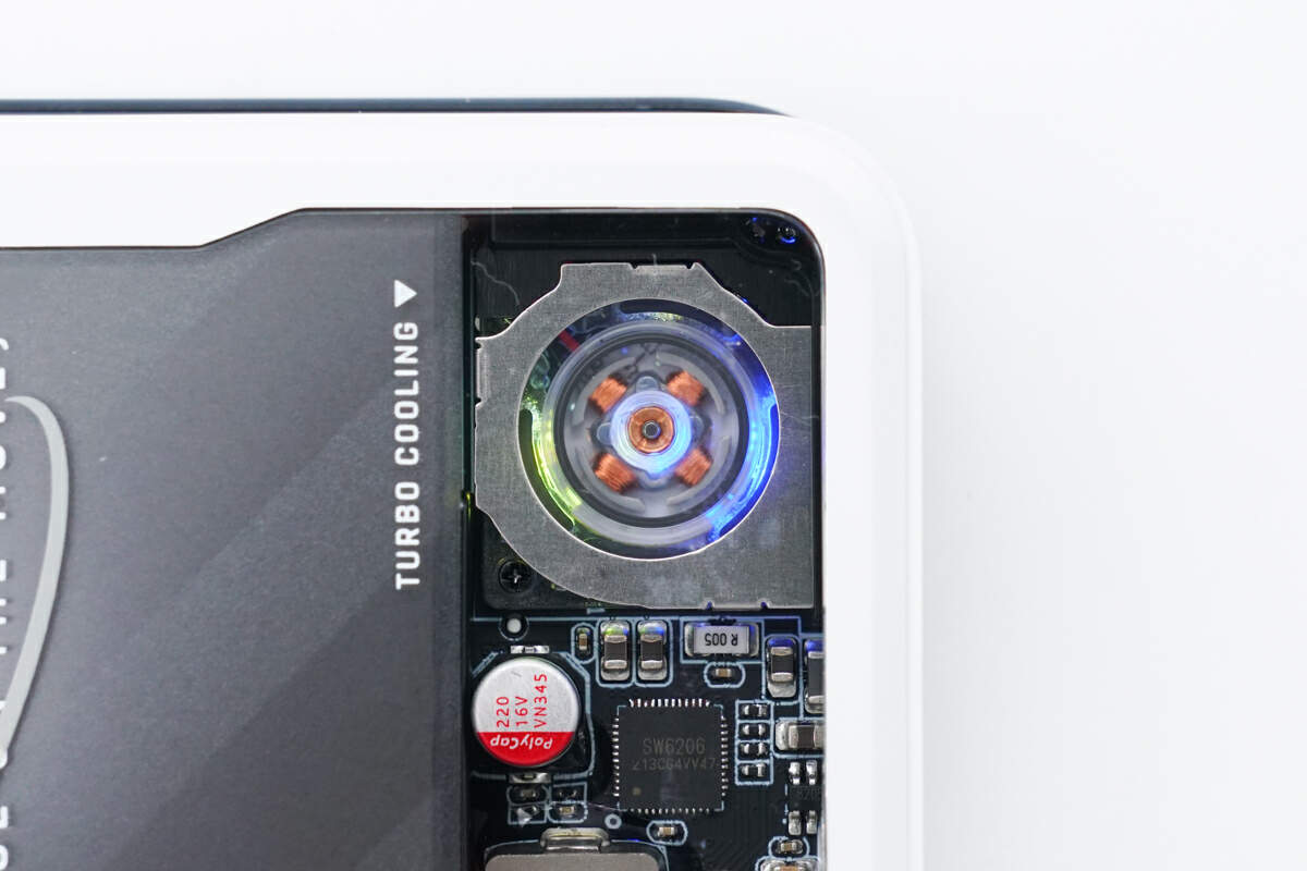
It has a built-in cooling fan and comes with colorful lights. Let it dissipate heat and have a cool effect at the same time.
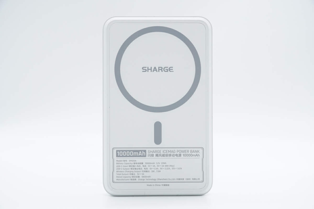
There are the wireless charging area and specs info.
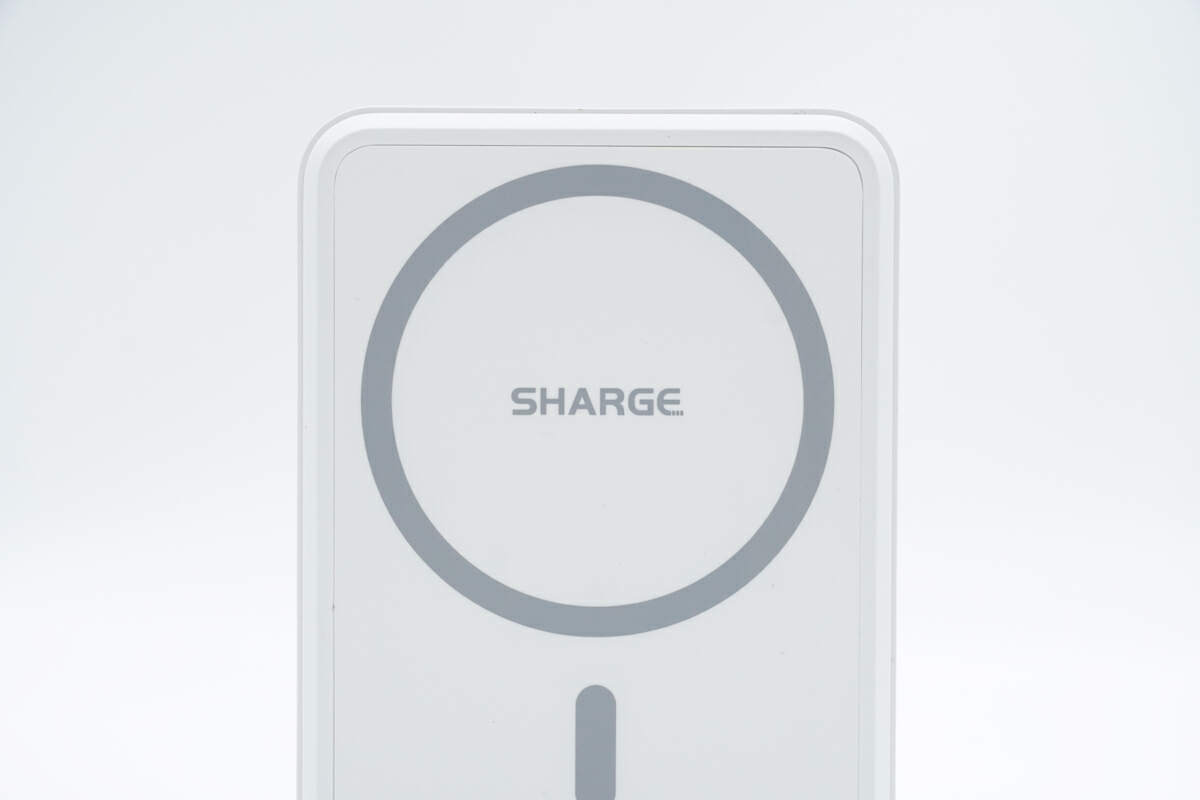
The "SHARGE" is printed in the center of the wireless charging area.
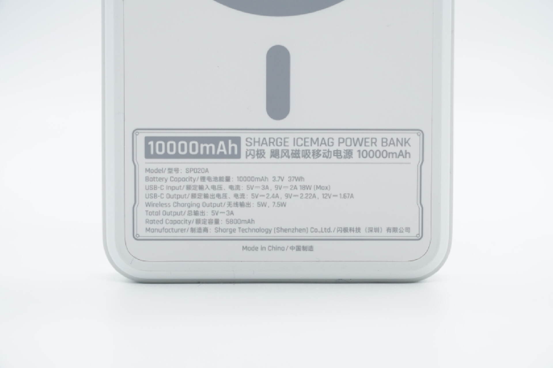
Here are the specs info. Model is SP020A. The battery capacity is 10000mAh 3.7V 37Wh. The rated capacity is 5800mAh. The USB-C can support input of 5V3A, 9V2A 18W (Max).
And the USB-C can output at 5V2.4A, 9V2.22A, and 12V1.67A. The wireless charging power is 5W, 7.5W. The total output power is 5V3A 15W.
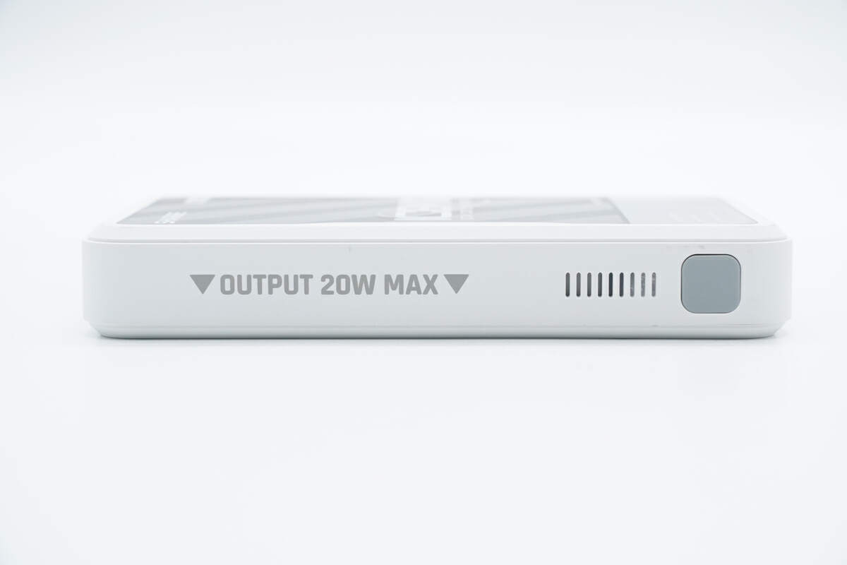
One side is equipped with a power button and ventilation.
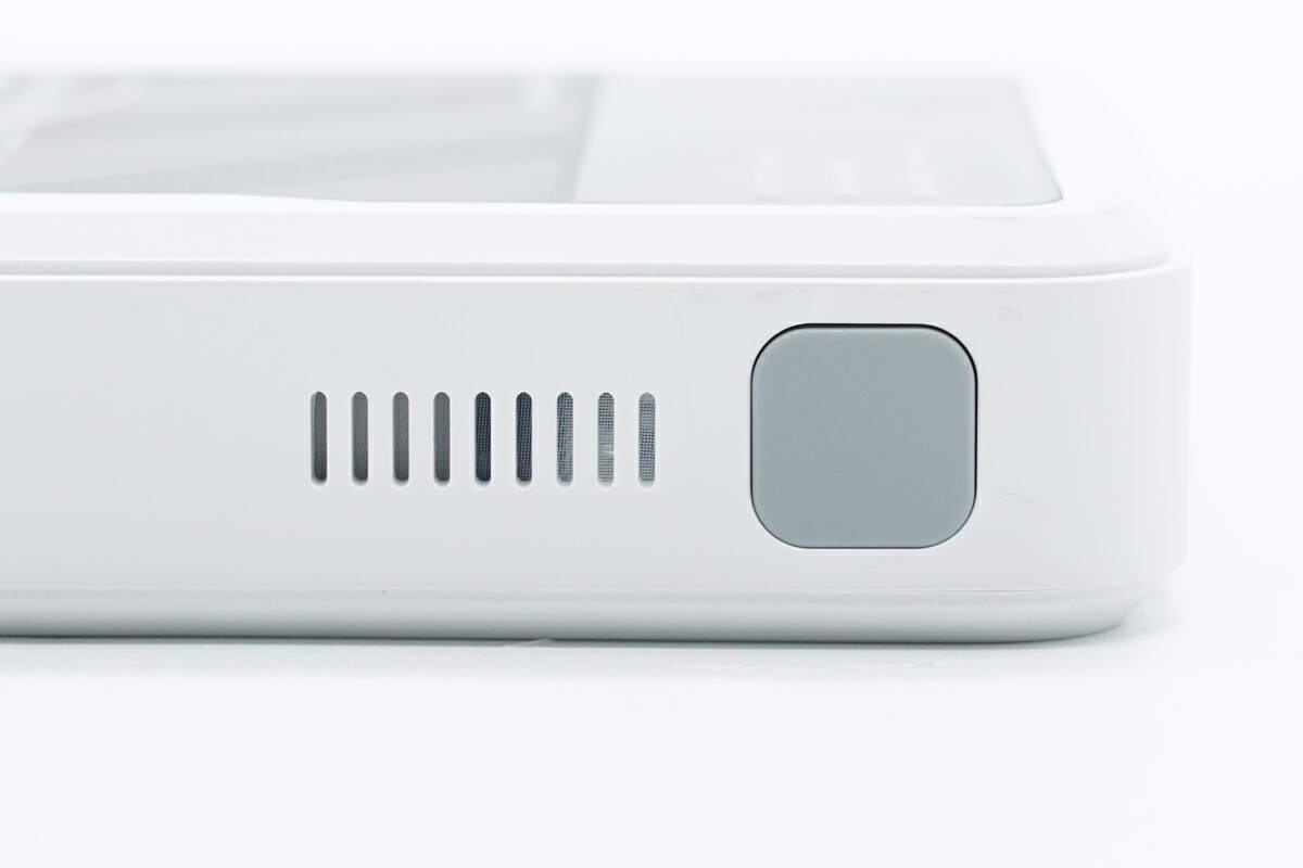
There is a dustproof net inside the ventilation.
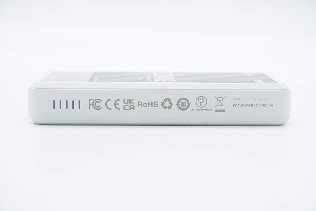
The other side is equipped with the power indicator lights. It is also printed with the logo of certification and has passed FCC, CE, UKCA, and PSE certifications.
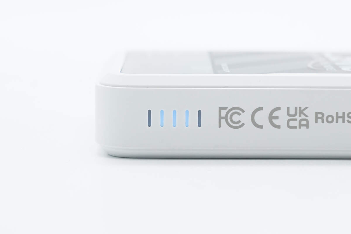
The light of the battery indicator is blue.
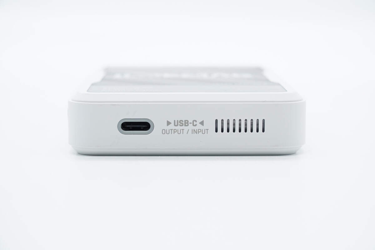
There is a USB-C port at the bottom and the ventilation is on this side.
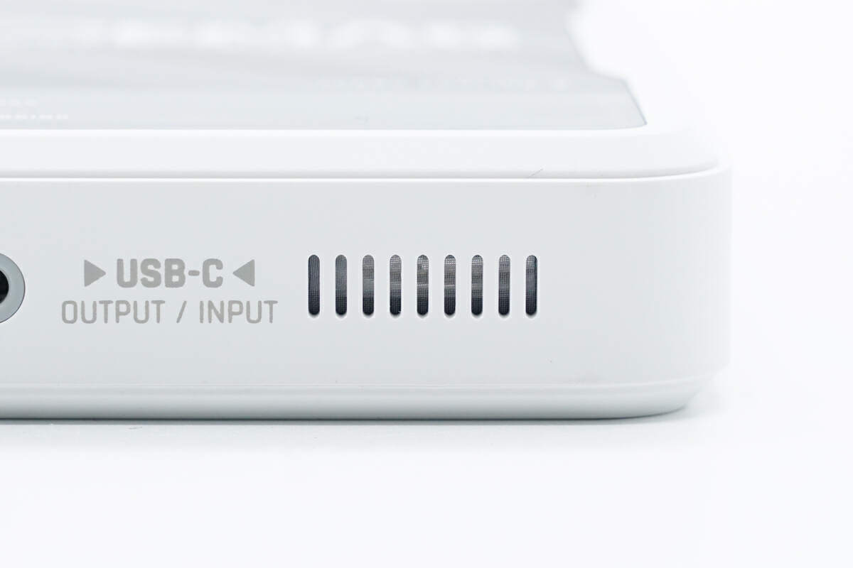
The ventilation here also has a dustproof net inside.
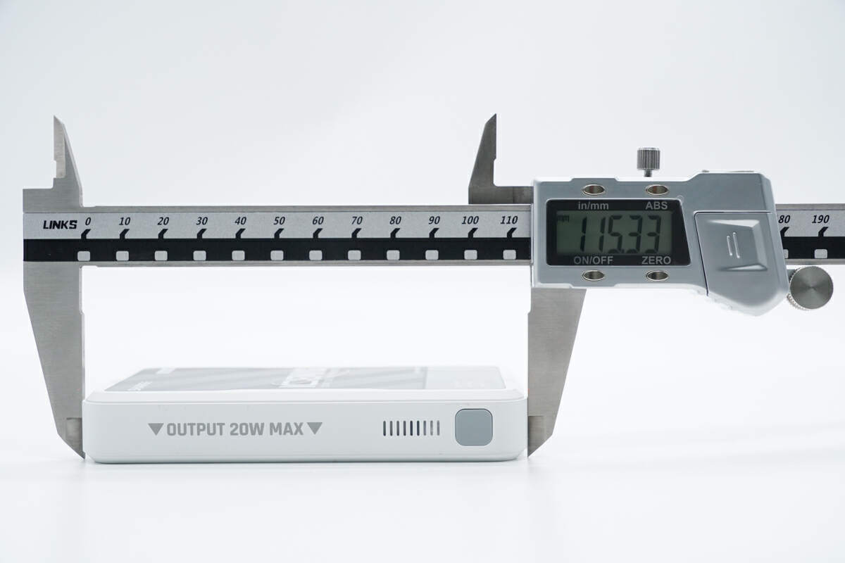
The length of it is about 115 mm (4.53 inches).
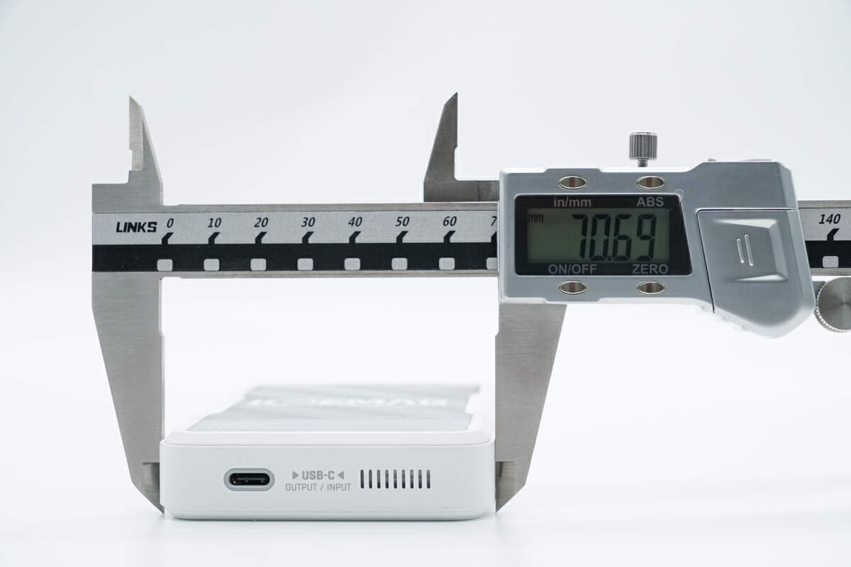
The width is about 71 mm (2.8 inches).
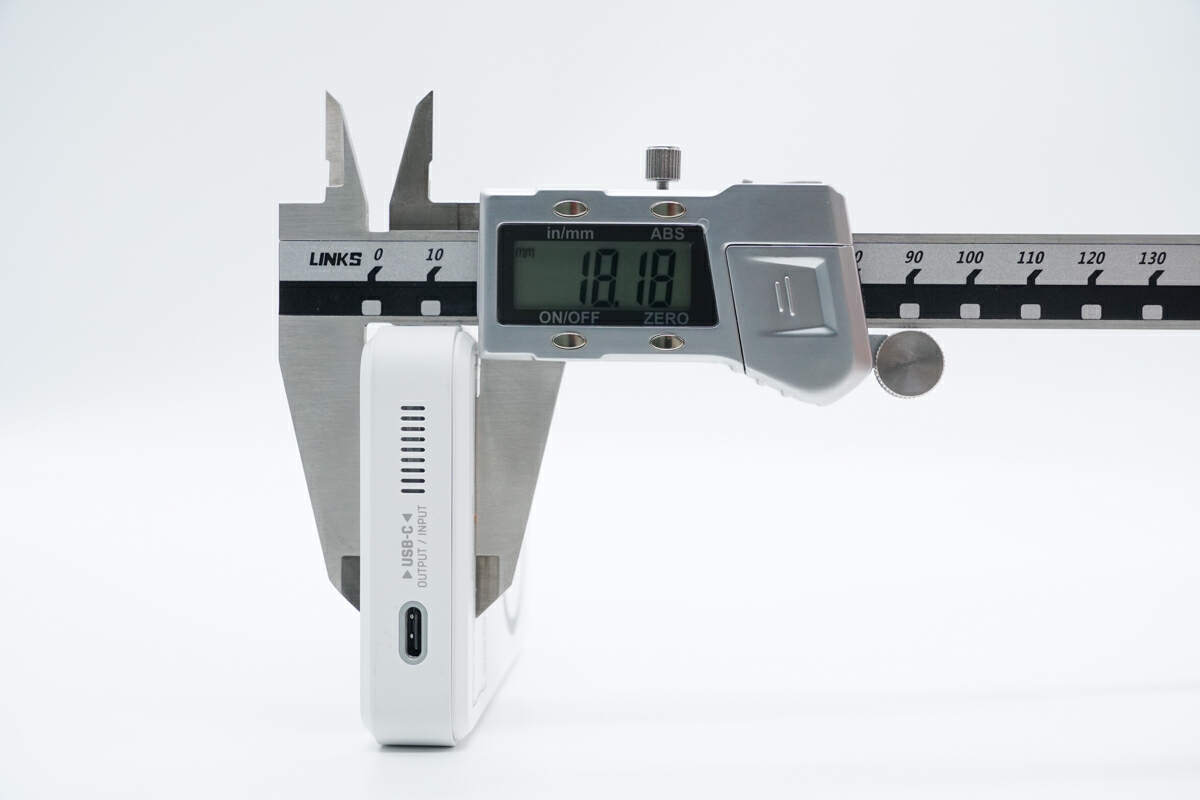
The thickness is about 18 mm (0.71 inches).
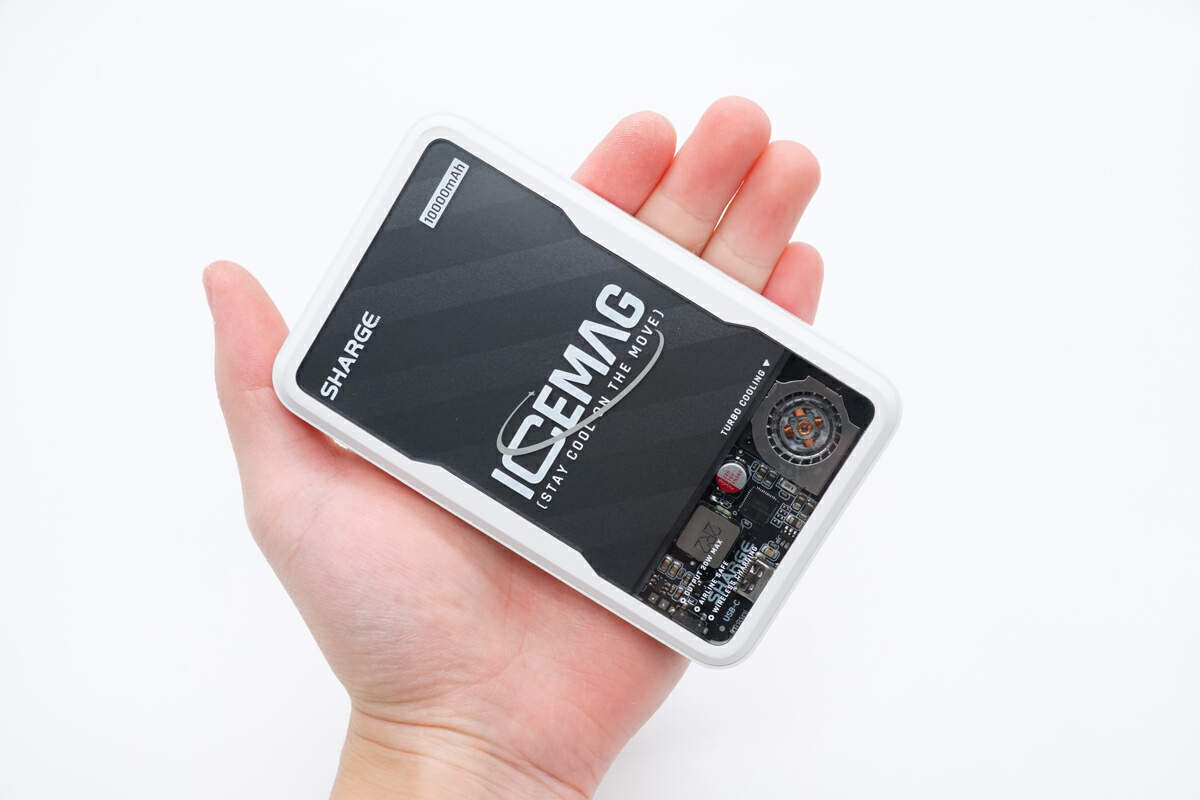
That's how big it is in the hand.
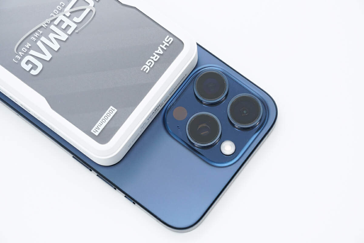
Use it to wirelessly charge the iPhone 15 Pro Max. It will not block the camera of the phone, making it convenient for users to take photos or record videos while charging.
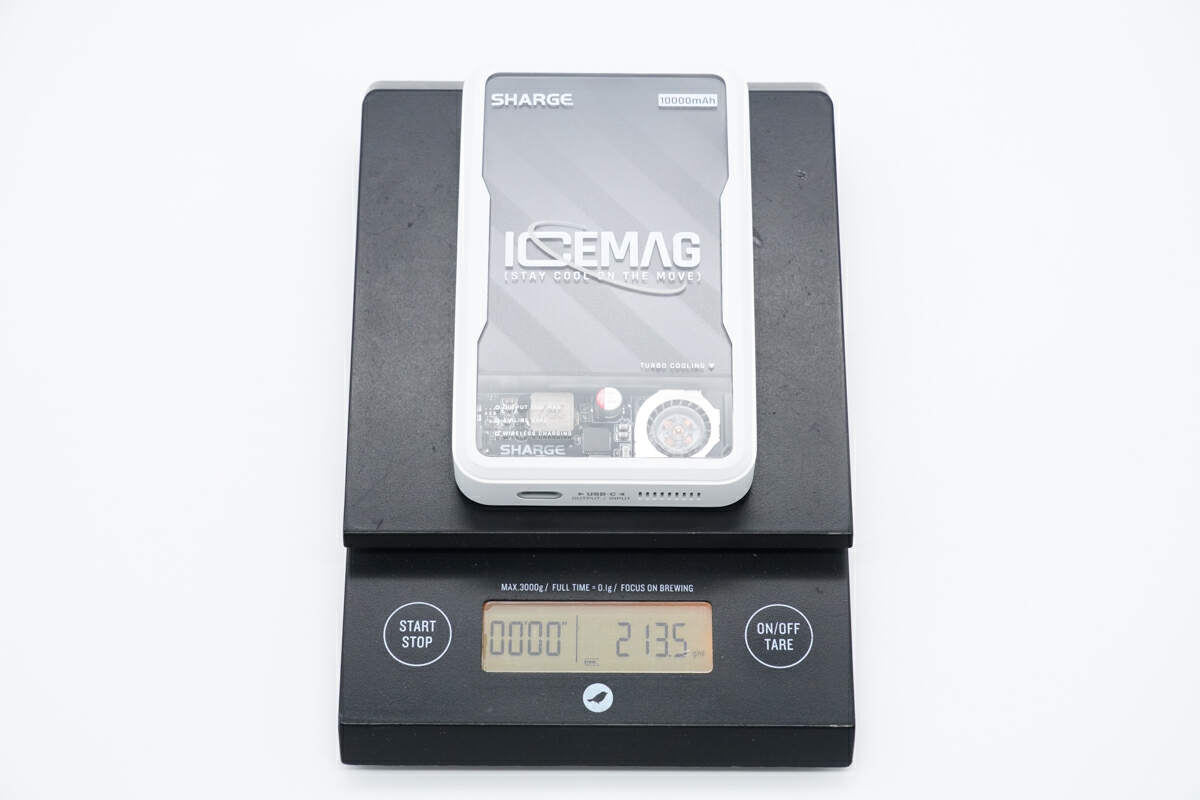
The weight is about 214 g (7.55 oz).
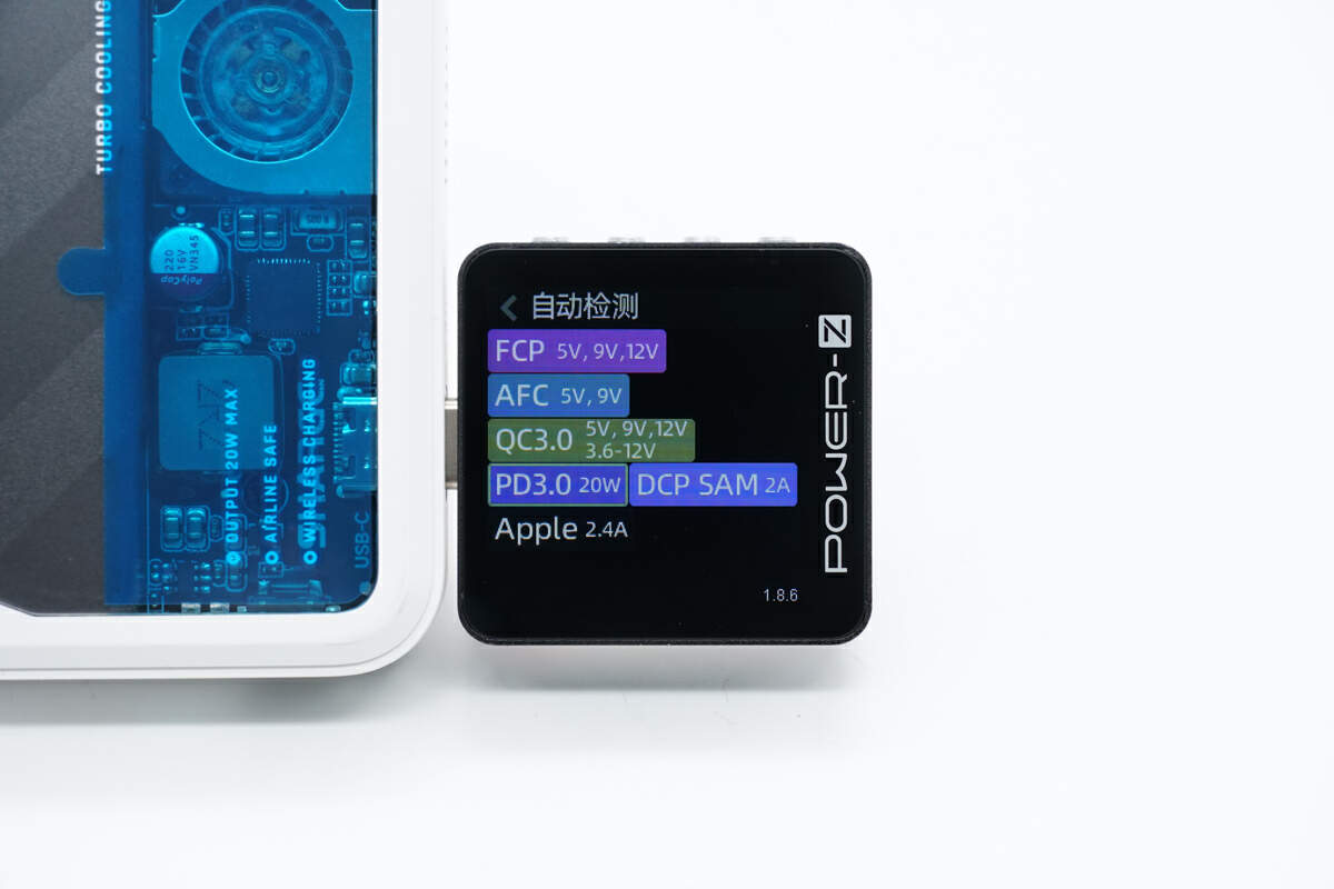
The ChargerLAB POWER-Z KM003C shows the USB-C port supports FCP, AFC, QC3.0, PD3.0, DCP, SAM 2A, and Apple 2.4A charging protocols.
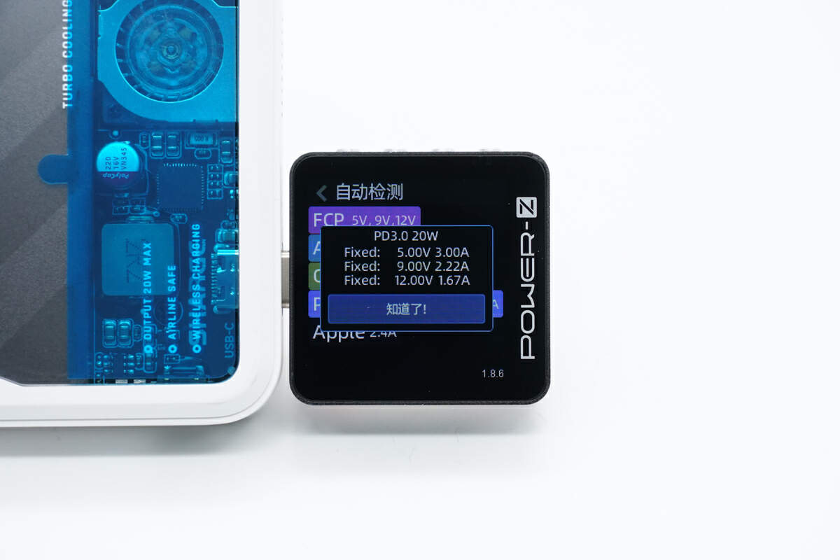
And it has three fixed PDOs of 5V3A, 9V2.22A, and 12V1.67A.
Teardown
After the product's appearance, let's start to take it apart.
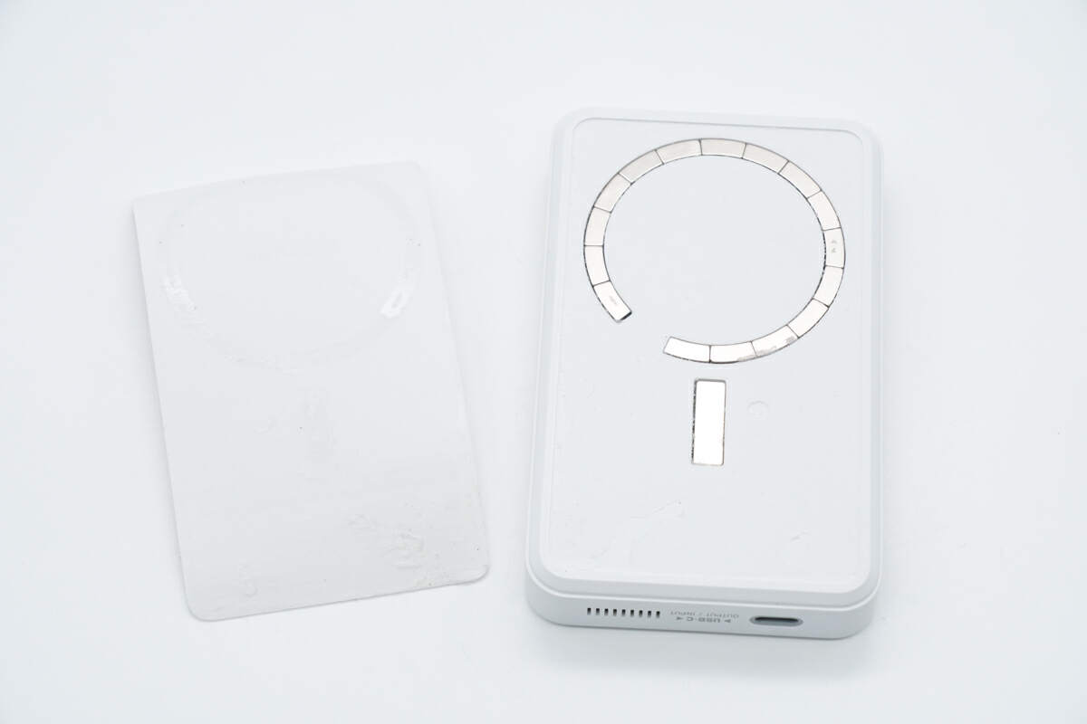
First, uncover the silicone sheet of the wireless charging panel. The magnets used to absorb the mobile phone are inside.
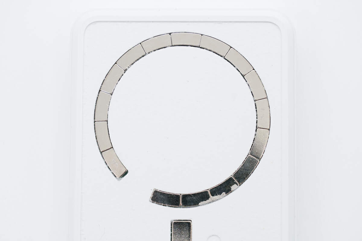
There are a total of 16 magnets forming the magnet ring.
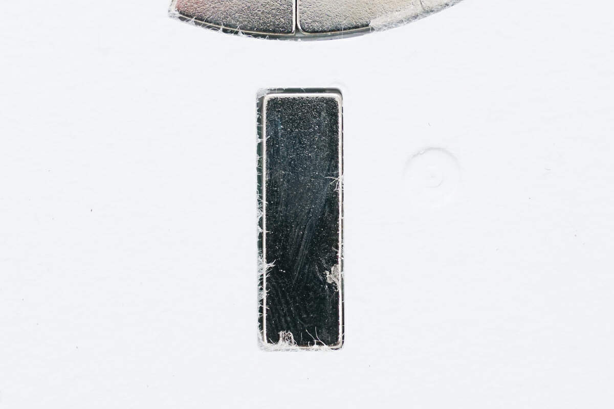
This is the magnet for positioning.
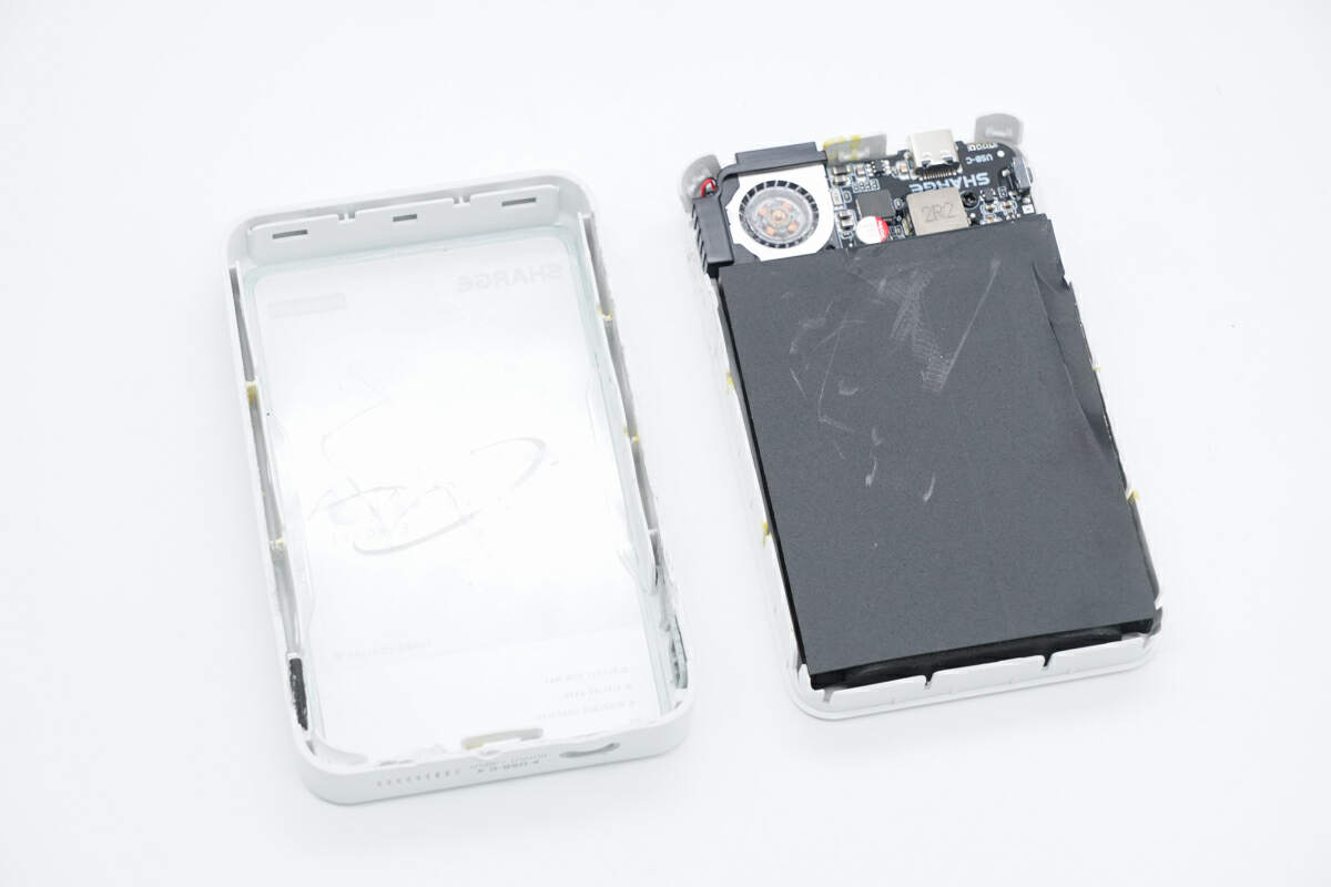
Take apart the case along the gap. The case is fixed with clips.
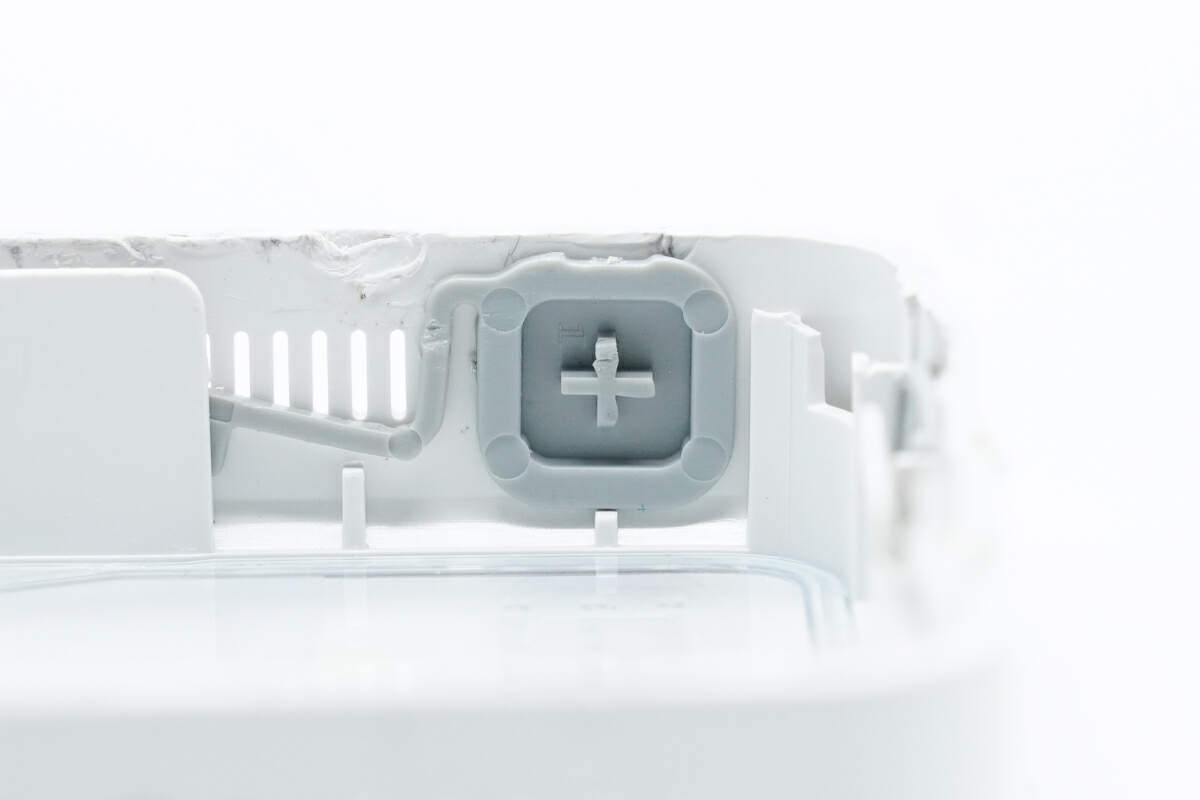
Here is the inside of the power button.
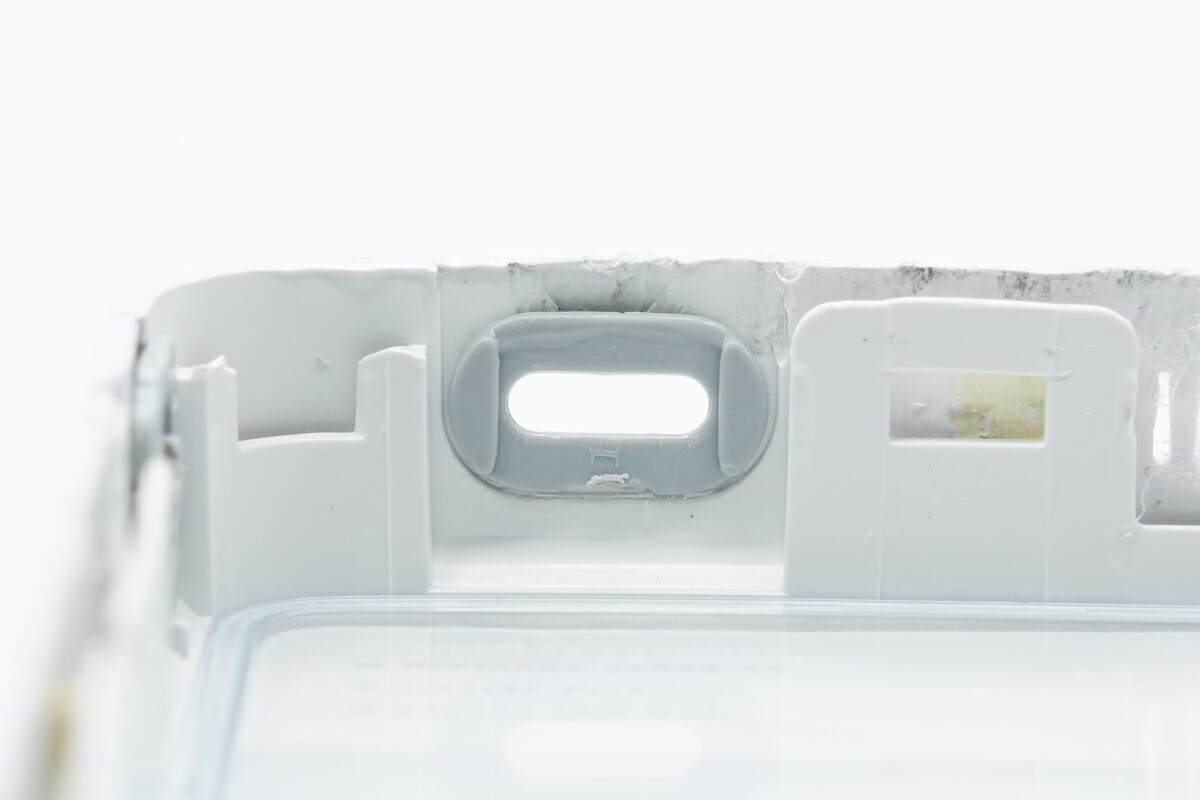
The USB-C female socket is equipped with a plastic ring.
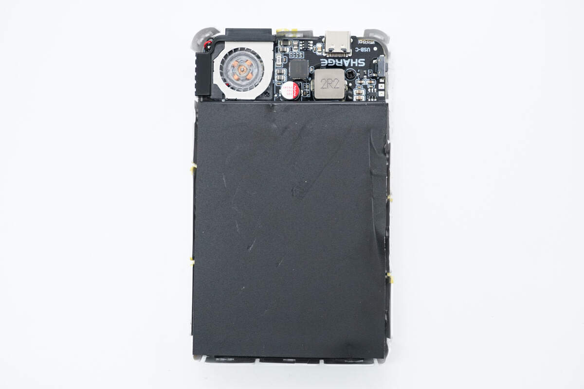
This is the battery and the PCBA module. The black mylar sheet is attached to the battery.
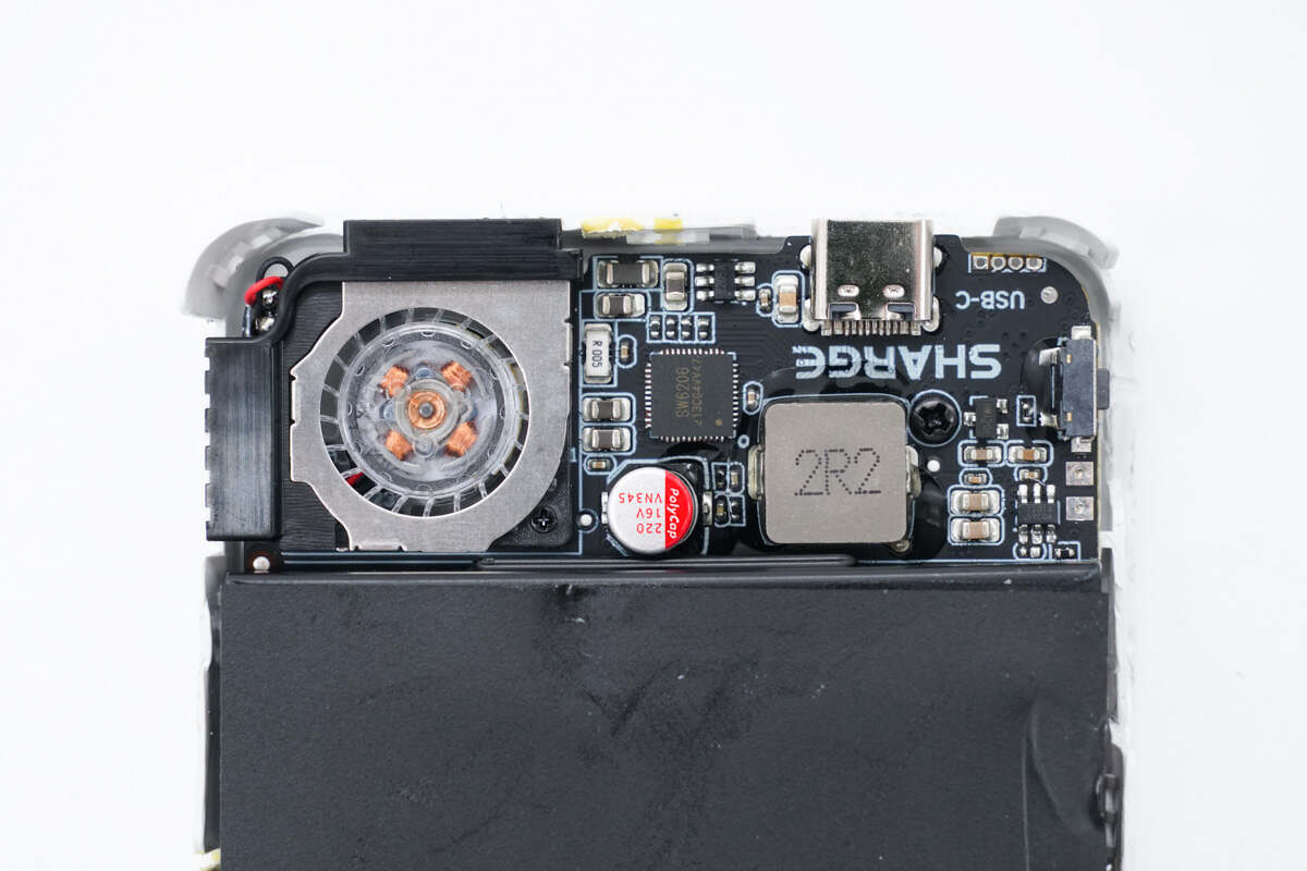
The cooling fan is on the left side of the PCBA module. The master control chip, inductor, and USB-C socket are on the right side.
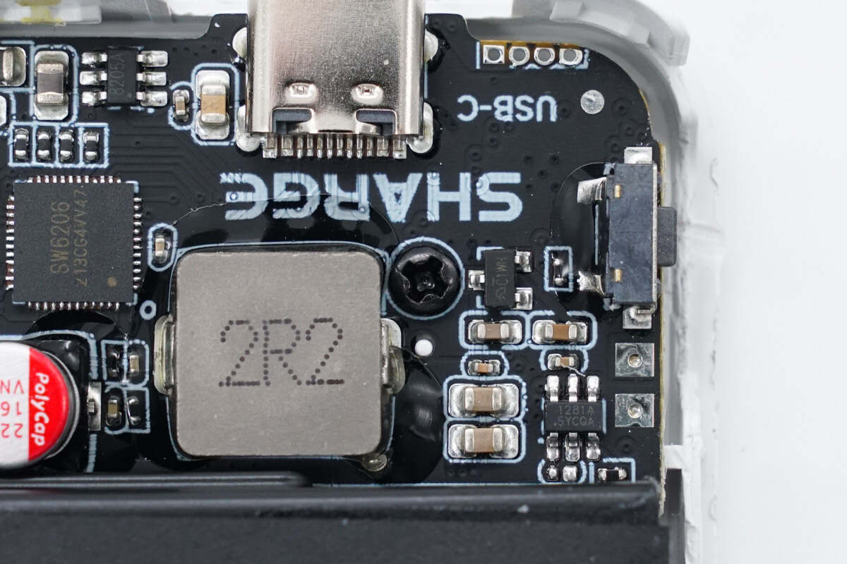
The PCBA module is fixed with screws.
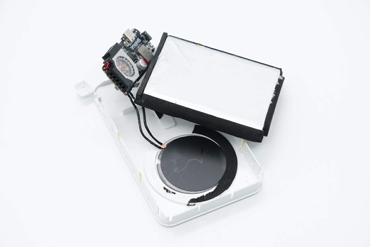
Take out the PCBA module and battery from the case. The edges of the battery are wrapped with foam for protection.
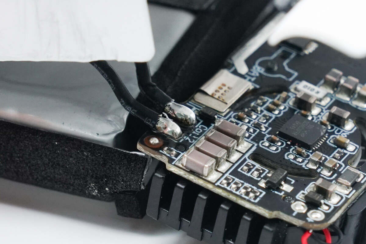
The wireless charging coil is soldered to the PCBA module.
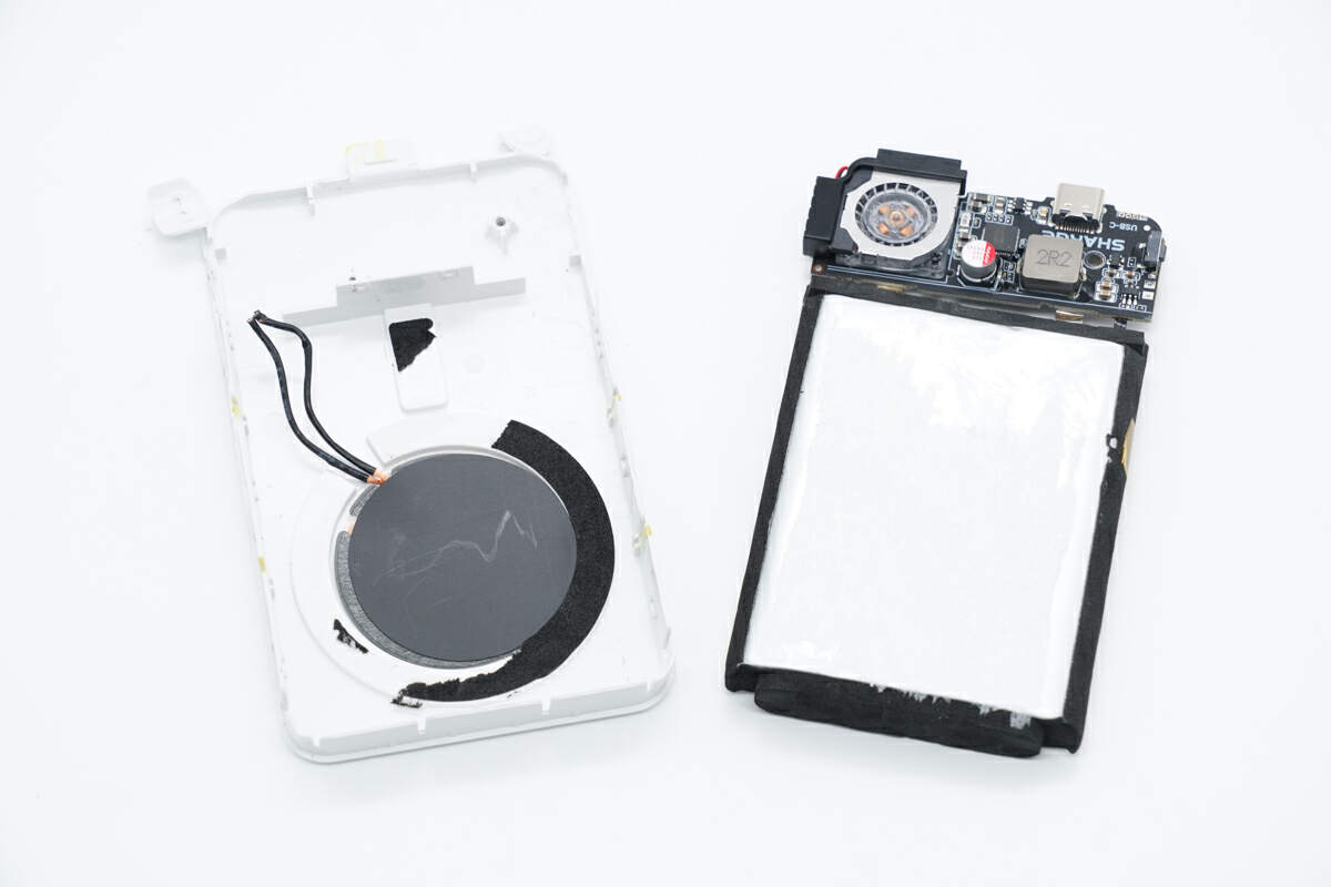
Separate the connections between the PCBA module and the wireless charging coil.
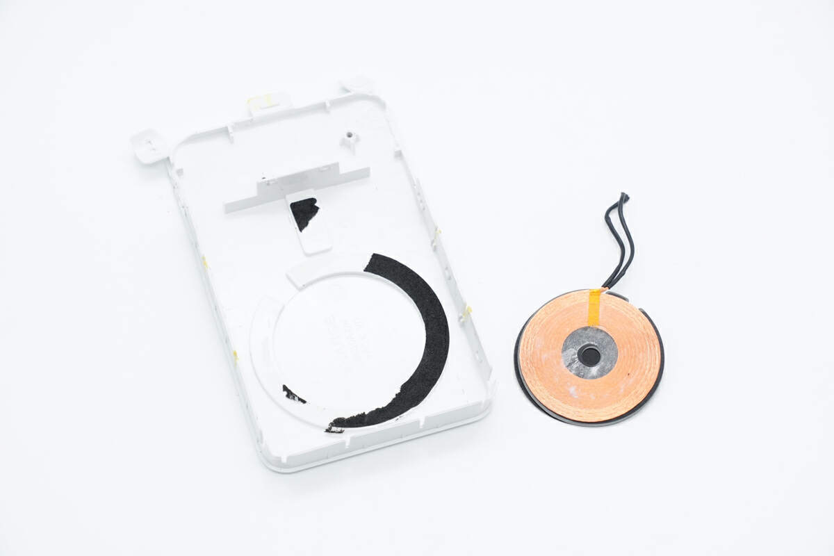
The wireless charging coil is pasted inside the case. The wires are insulated by heat-shrinkable tubing.
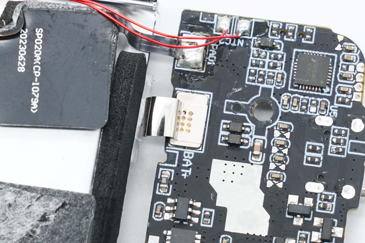
The battery is soldered to the PCBA module.
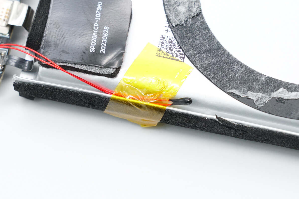
A thermistor is attached to the side of the battery to detect the temperature.
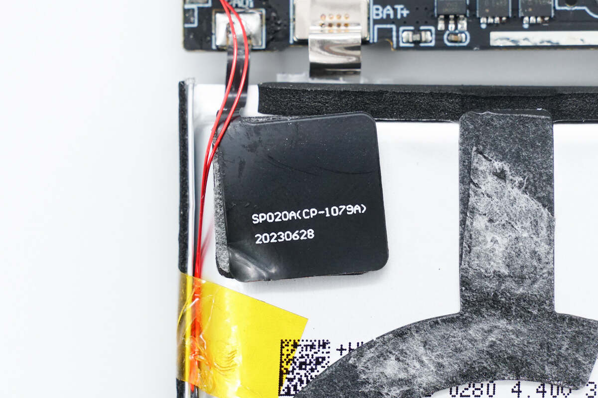
There is a patch on the battery to detect the distance from the phone.
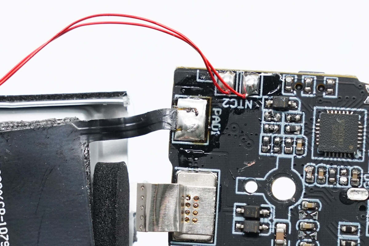
The patch is soldered to the PCBA module.
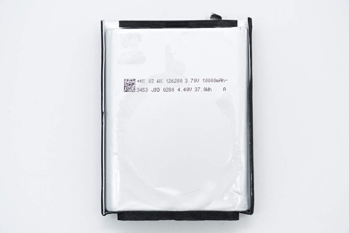
The size of the battery is 126280. The rated voltage of the battery is 3.7V, the charging limit voltage is 4.4V, the capacity is 10000mAh, and the energy is 37Wh.
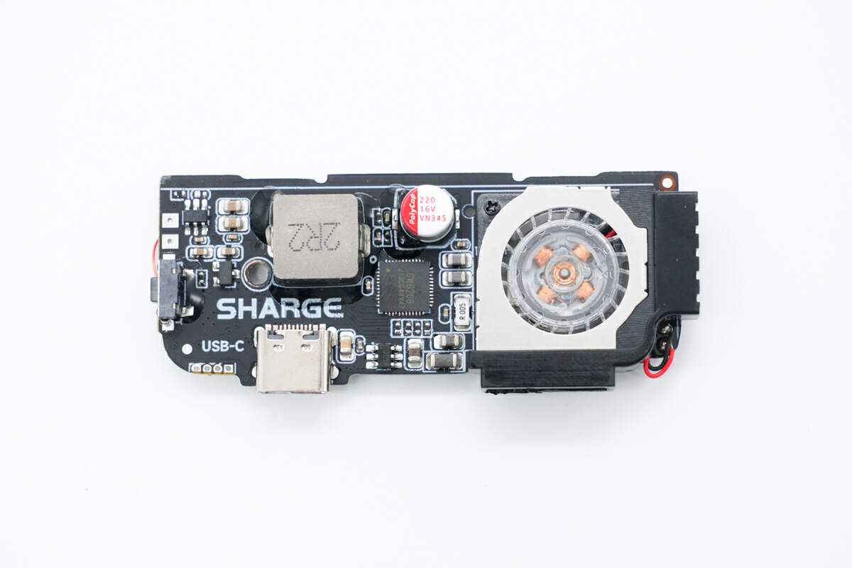
The SMD button, USB-C female socket, master control chip, alloy inductor, solid capacitor, and fan are on the front of the PCBA module.
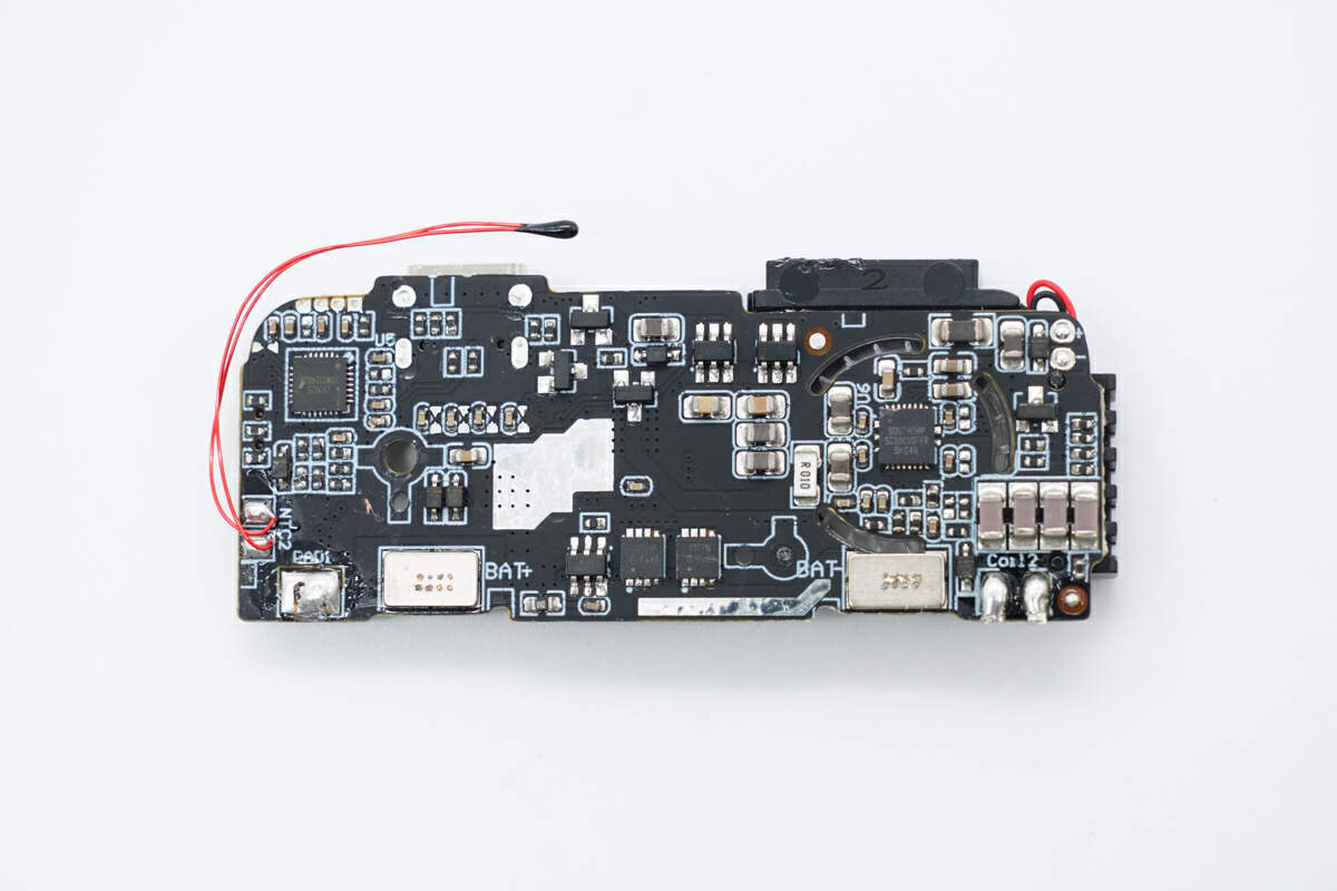
The resonant capacitor, battery protection chip, and MOSFET are on the back of the PCBA module.
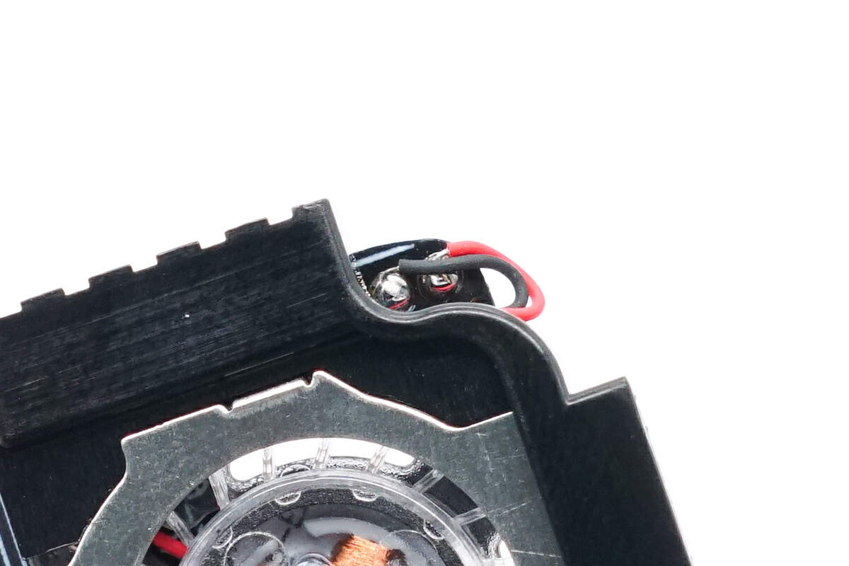
The cooling fan is connected by soldering.
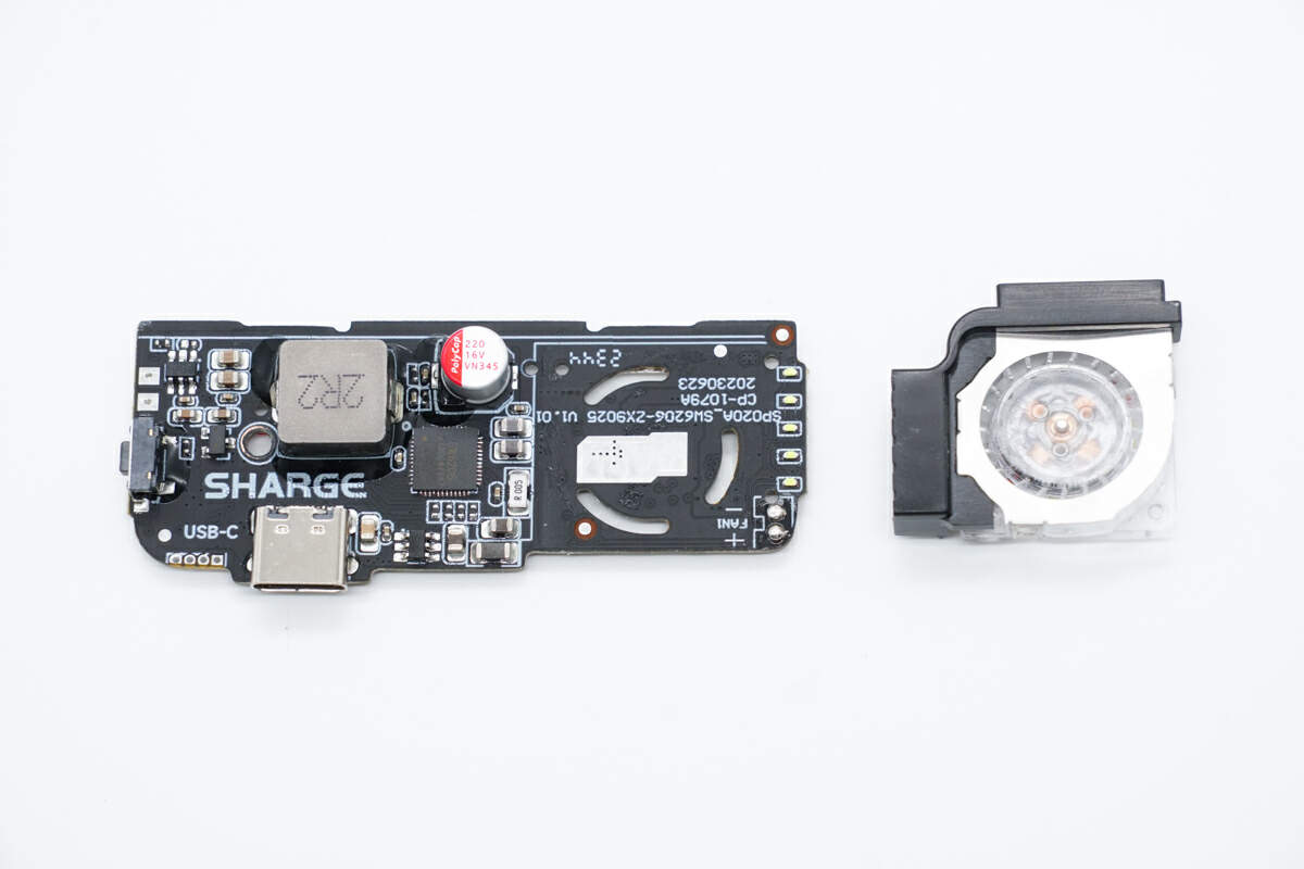
Remove the cooling fan and find that the PCBA module is slotted to enhance heat dissipation.
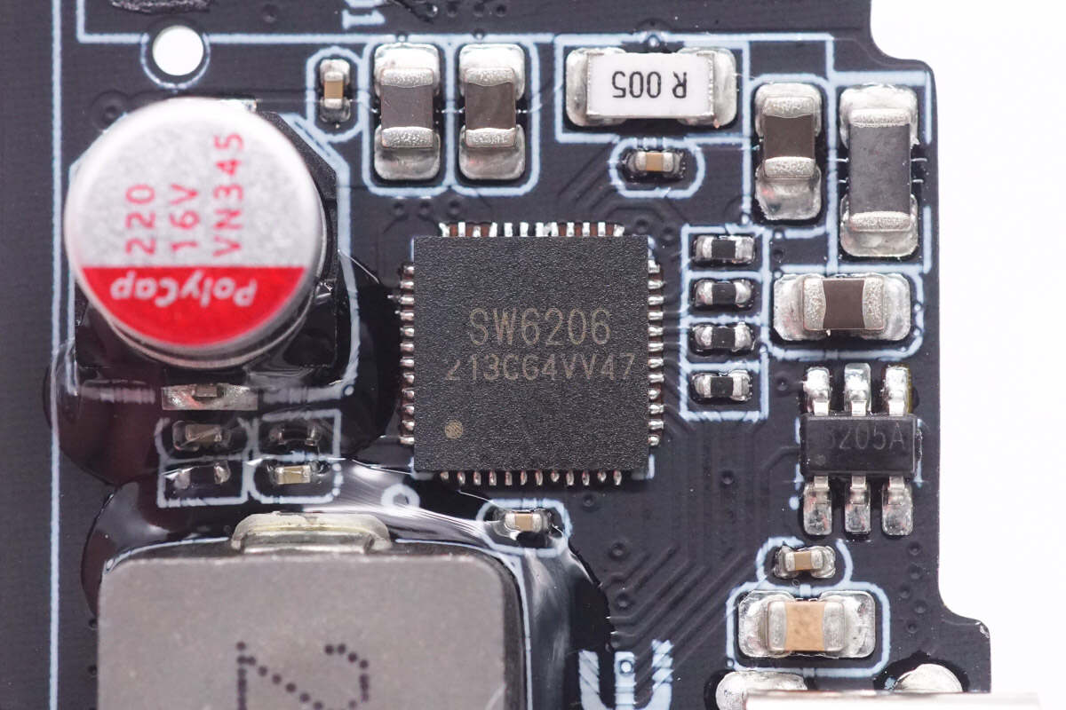
The master control chip is from iSmartWare. It is a highly integrated multi-protocol chip for power banks. It also supports fast charging of any A+A+B+C+L port. Model is SW6206.
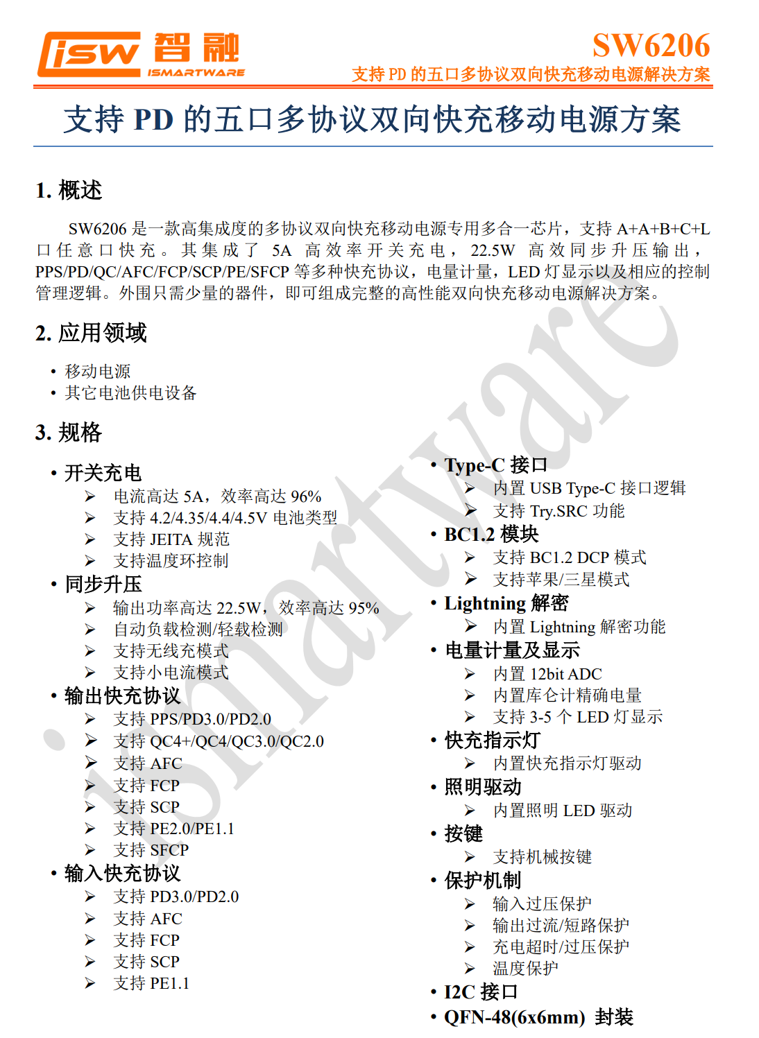
Here is all the information about the iSmartWare SW6206.
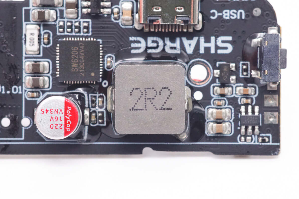
The bottom of the alloy inductor is reinforced with glue. 2.2μH.
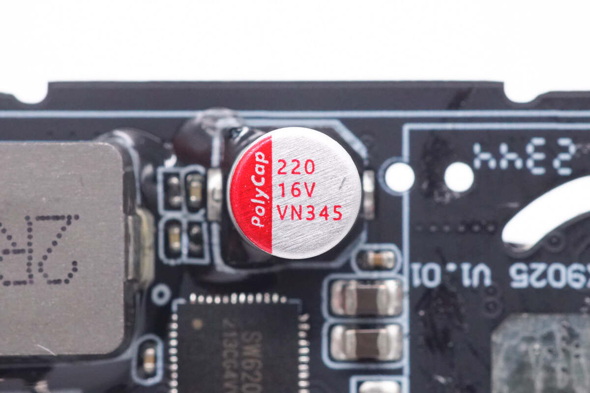
The solid capacitor is from PolyCap VN series. 220μF 16V.
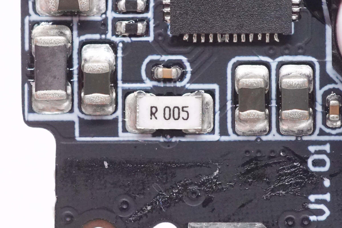
The sampling resistor is used to detect the output current. 5mΩ.
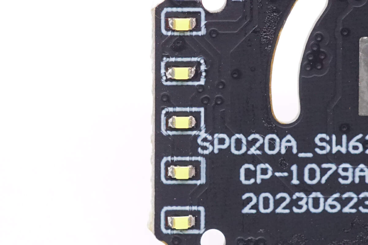
These are five LED indicators used to display the remaining battery power.
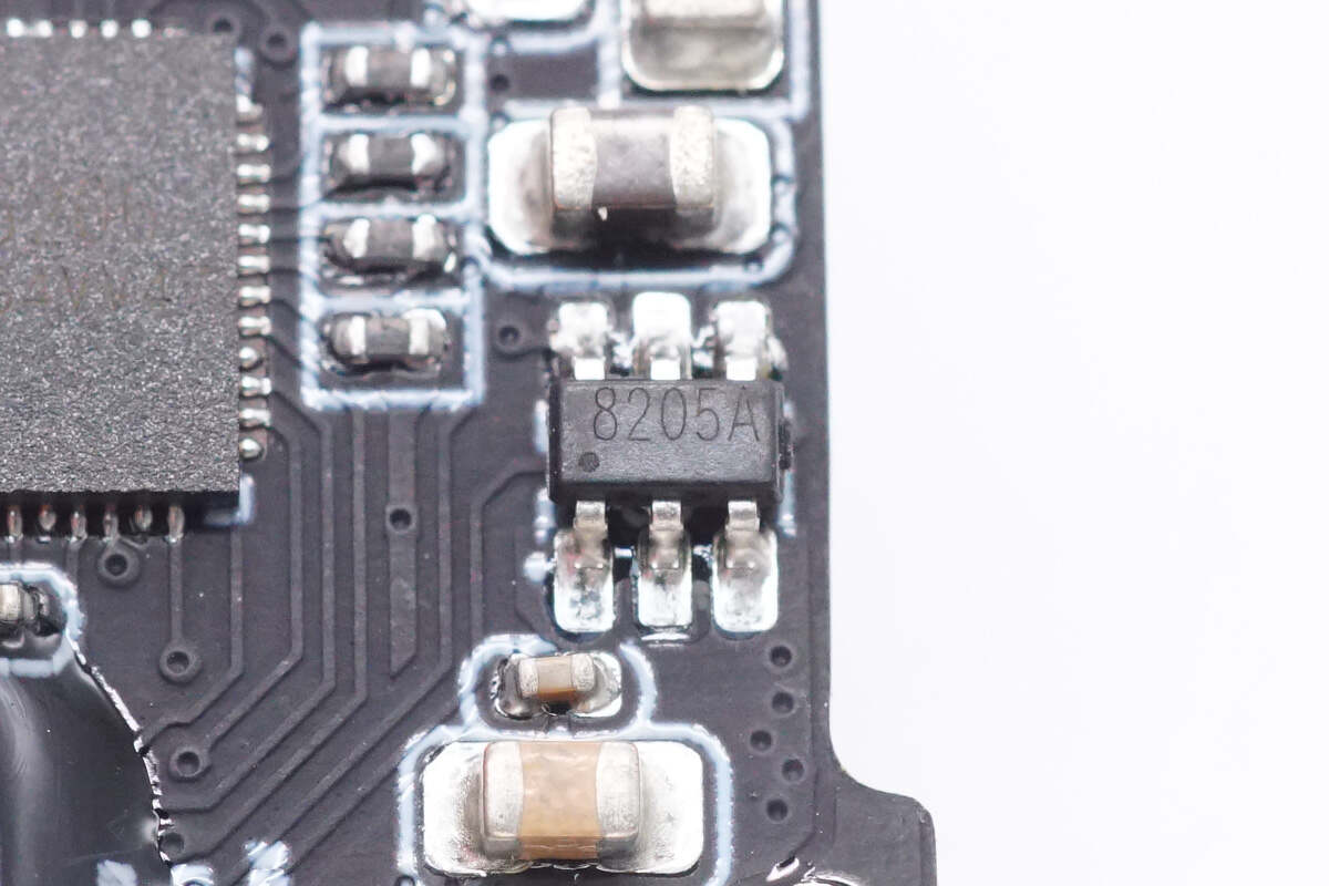
The MOSFET marked with 8205A is used for VBUS control of the USB-C port.
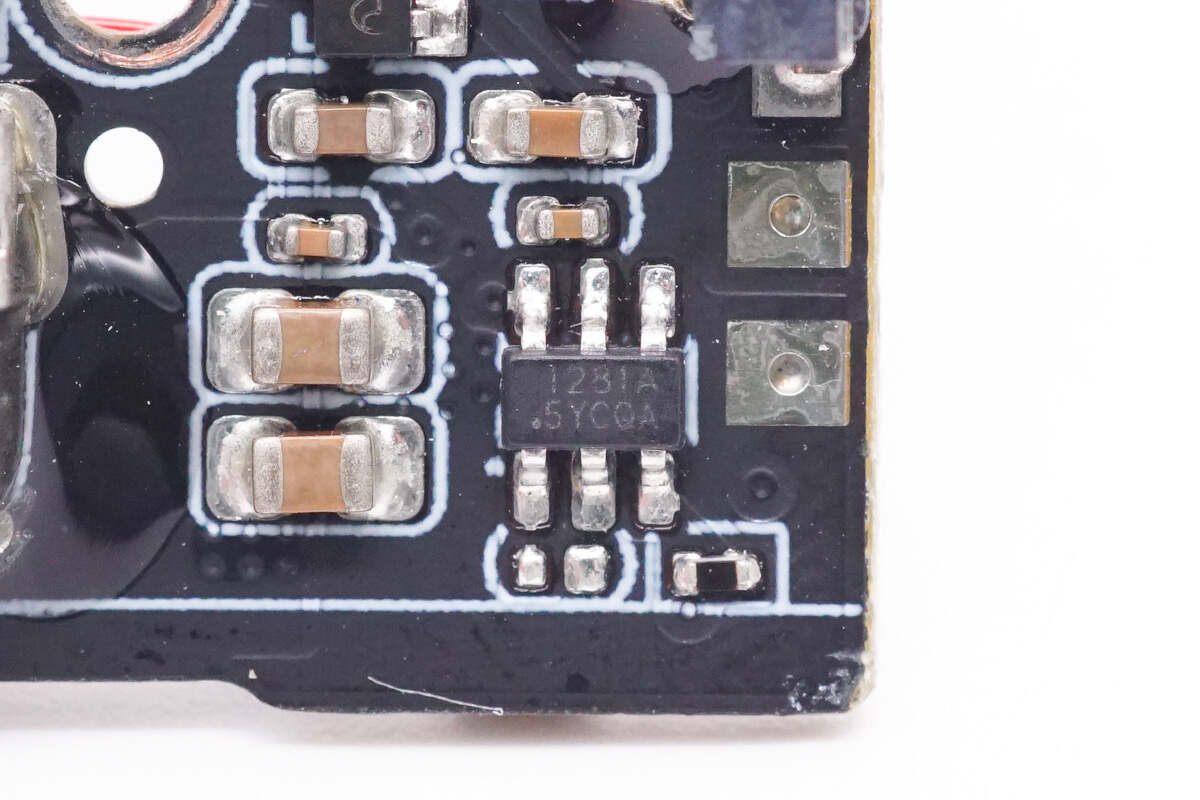
The touch detection chip is marked with 1281A.
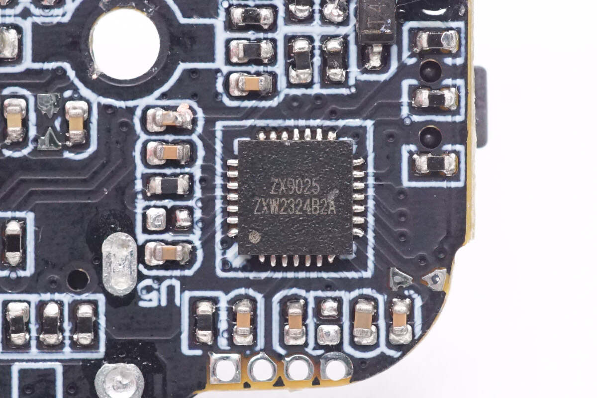
The wireless charging master control chip is from ZXWTek. It can improve product scalability and enable functional customization to achieve differentiated design. It can perform firmware upgrades through the USB port. Model is ZX9025.
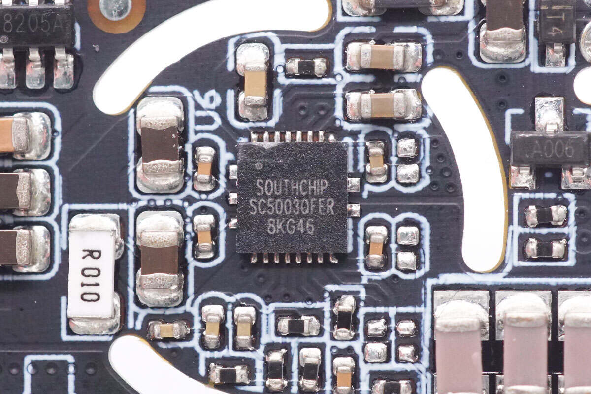
The wireless power transmitter is from SouthChip. It integrates a full-bridge power driver with MOSFETs, current sense amplifier, bootstrap circuit, communication demodulator, and protection circuit. It supports 20W output power and is compatible with 1.2.4 BPP and EPP protocols. Model is SC5003.
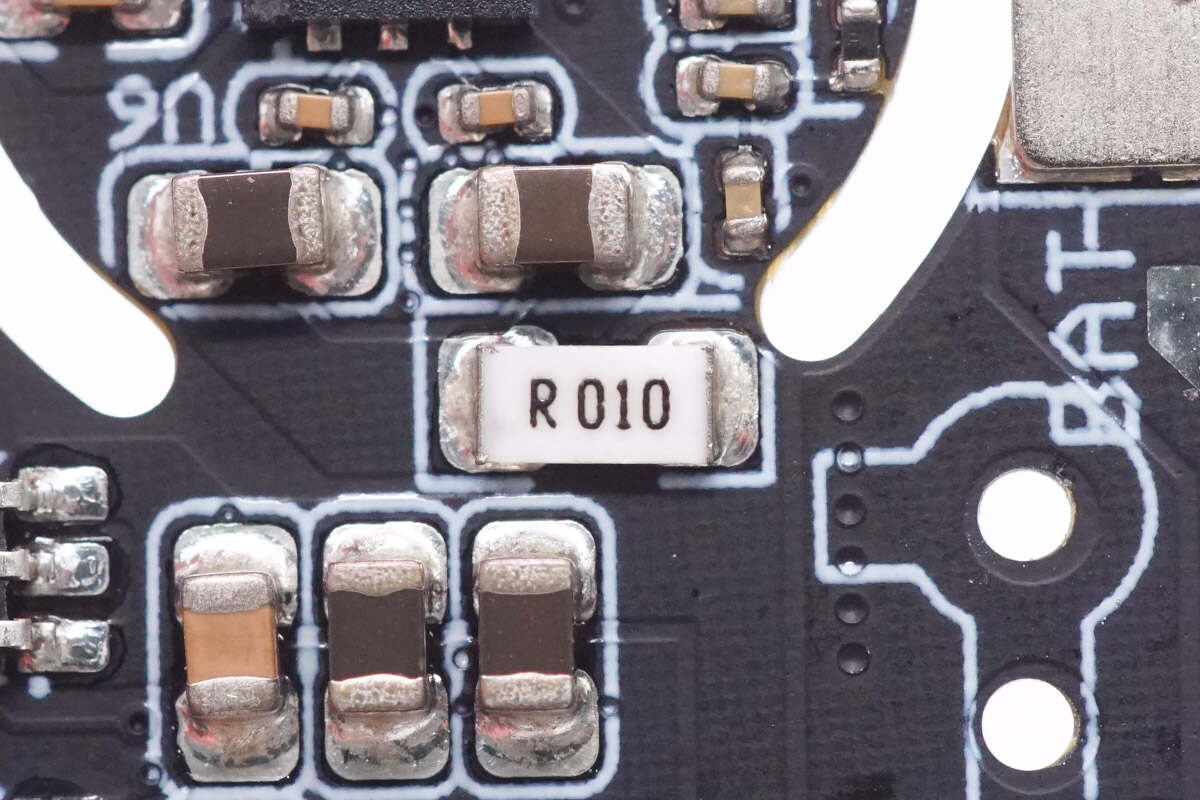
The sampling resistor is used to detect the current of the wireless power transmitter. 10mΩ.
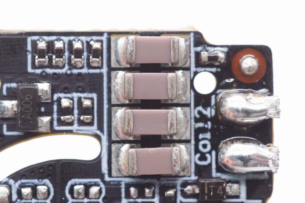
This is the NPO resonant capacitor.
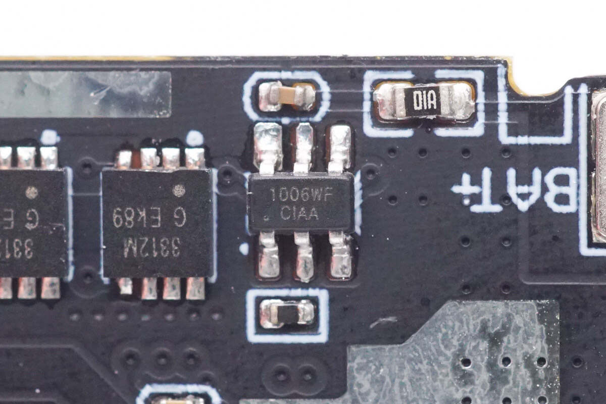
The battery protection chip is from MadeChip. It supports over-charge, over-discharge, and over-current protection. Model is CM1006-WF.
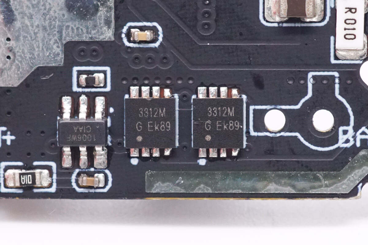
The battery protection MOSFETs are from Semi-one and adopt DFN3 x 3-8L package. Model is PED3312M. 18V 3.4mΩ.
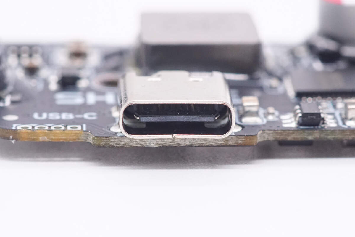
Here is the black USB-C port.
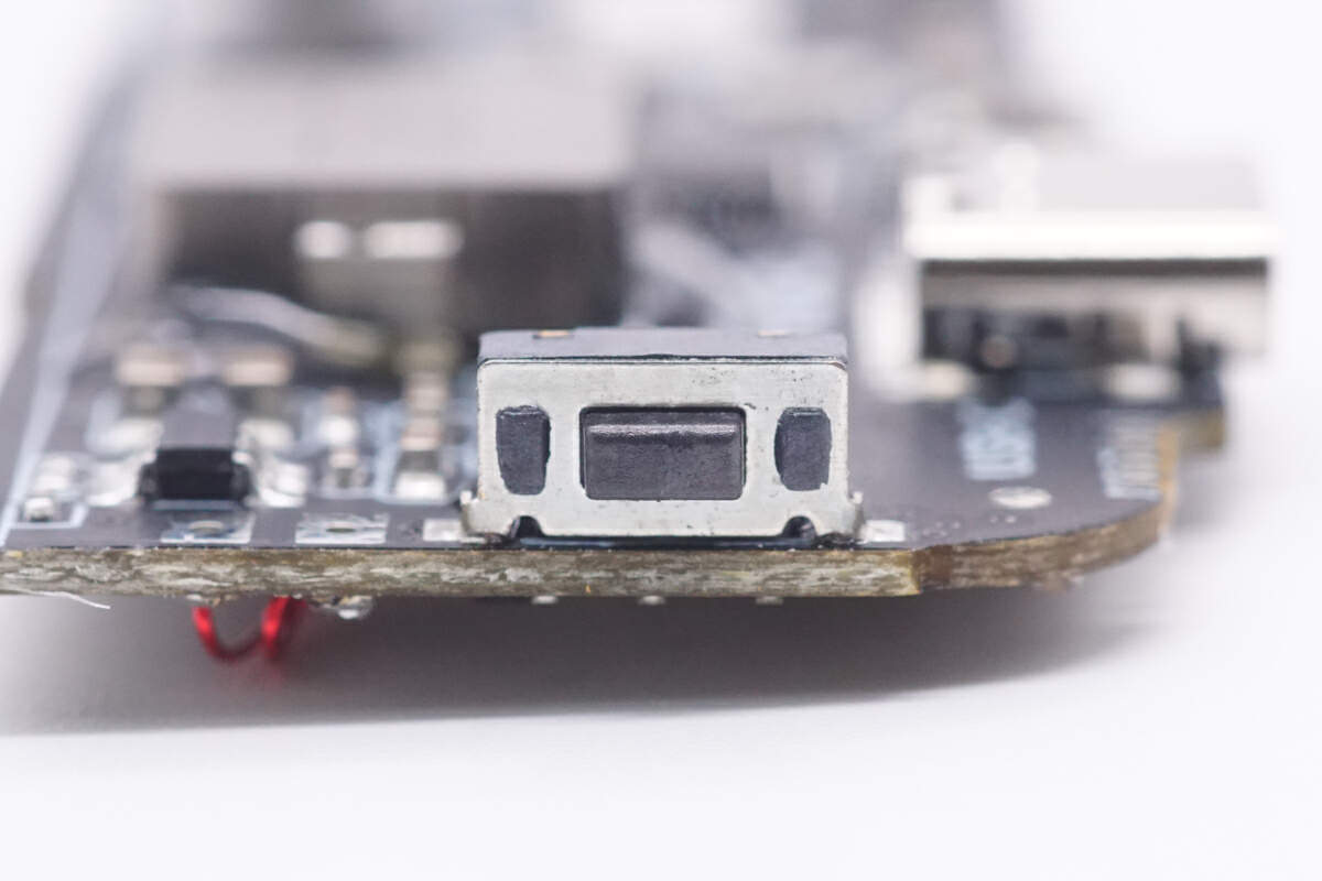
This is the SMD power detection button.
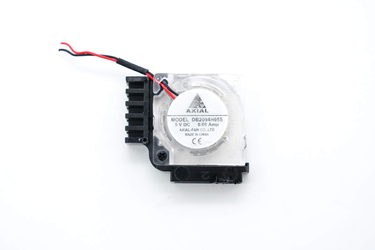
The centrifugal fan is from Axial-fan. Model is DB2004H05S. 5V 0.08A.
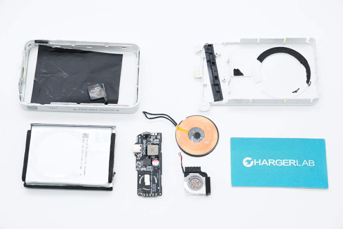
Well, those are all components of the SHARGE 10000mAh Magnetic Wireless Power Bank.
Summary of ChargerLAB
The SHARGE 10000mAh Wireless Magnetic Power has a built-in battery capacity of 10000mAh. The USB-C port supports an output of 20W, and the wireless charging power is 7.5W.
After taking it apart, we found the master control chip it adopts is from iSmartWare. The wireless charging master control chip is from ZXWTek, and the wireless power transmitter is from SouthChip. There is a fan inside to dissipate heat from the PCB. The edges of the battery are wrapped with foam for protection, and there is also an NTC thermistor used for temperature detection. Theoverall workmanship is solid. It can meet the wireless fast charging needs of Apple and Android phones.
Related Articles:
1. Teardown of IDMIX Q10 Pro 15W Magnetic Wireless Charging Power Bank with Stand
2. Review of Soodatek 20W Magnetic Wireless Power Bank
3. Teardown of CUKTECH 10000mAh 30W Power Bank

