Introduction
This time, ChargerLAB got a Lenovo 170W AC Power Adapter. Compared with Lenovo's old Power Adapter, it is thinner and significantly smaller in size. The power cord adopts a 3-prong design and is detachable, allowing different input lines to be replaced. The built-in output cable adopts the square connector of Lenovo. It can support an output power of 170W, which can meet the charging needs of high-power laptops.
Next, we are going to take it apart to see its internal components and structure.
Product Appearance
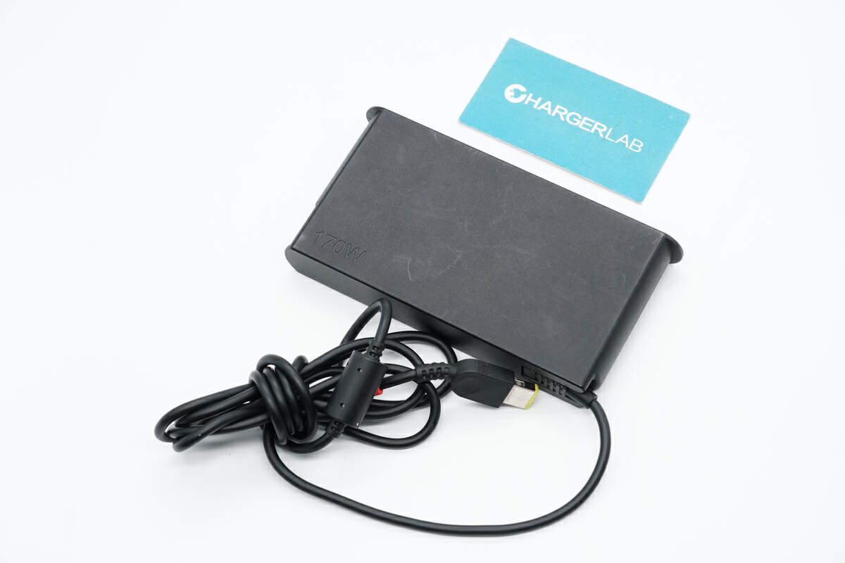
The input end of the adapter adopts a detachable design, allowing users to replace different power cords. The output end has a square connector, which can be adapted to various laptops of Lenovo.
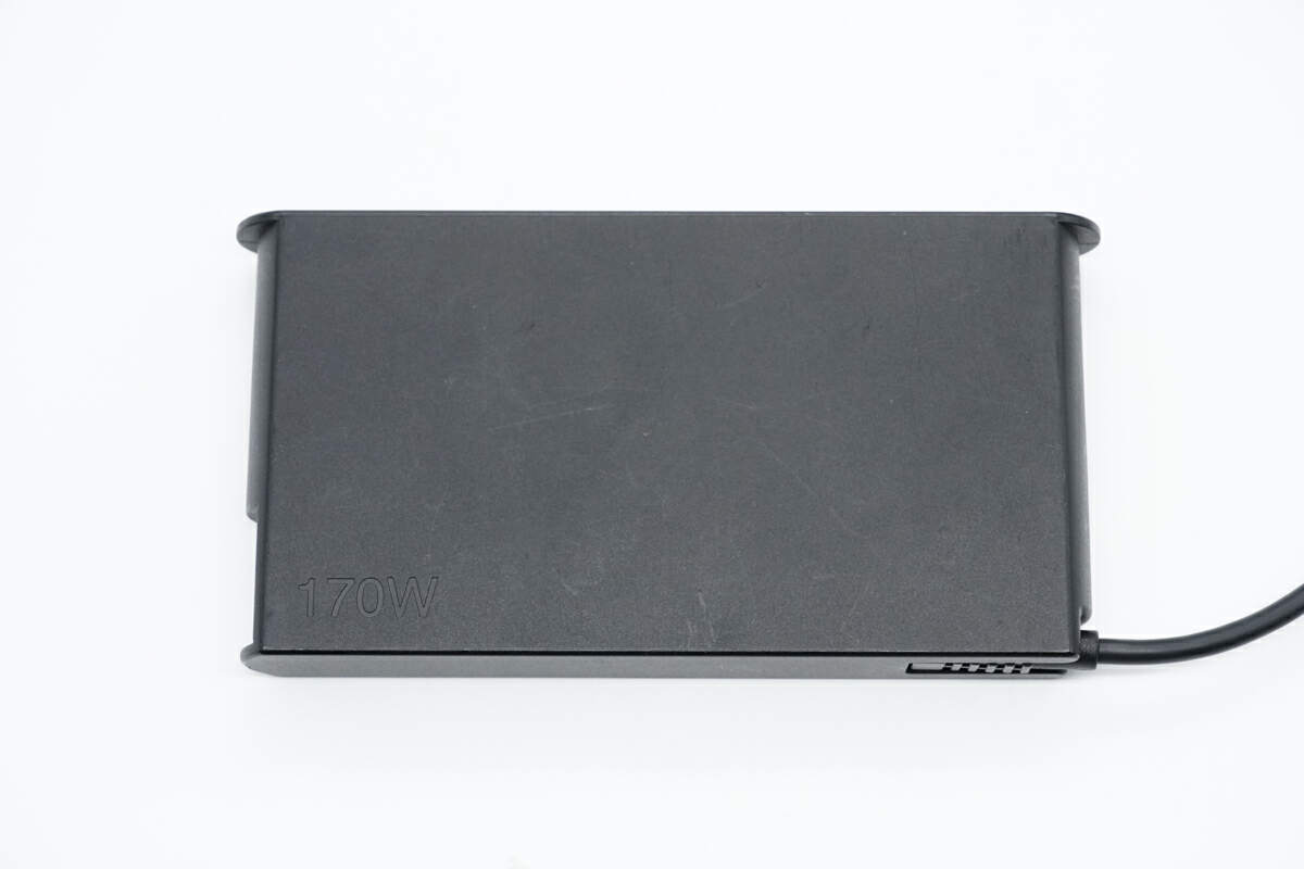
The case is made of fire-retardant PC material, and the surface has a matte design.
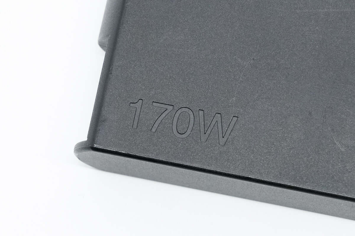
The lower left corner shows the maximum output power is 170W.
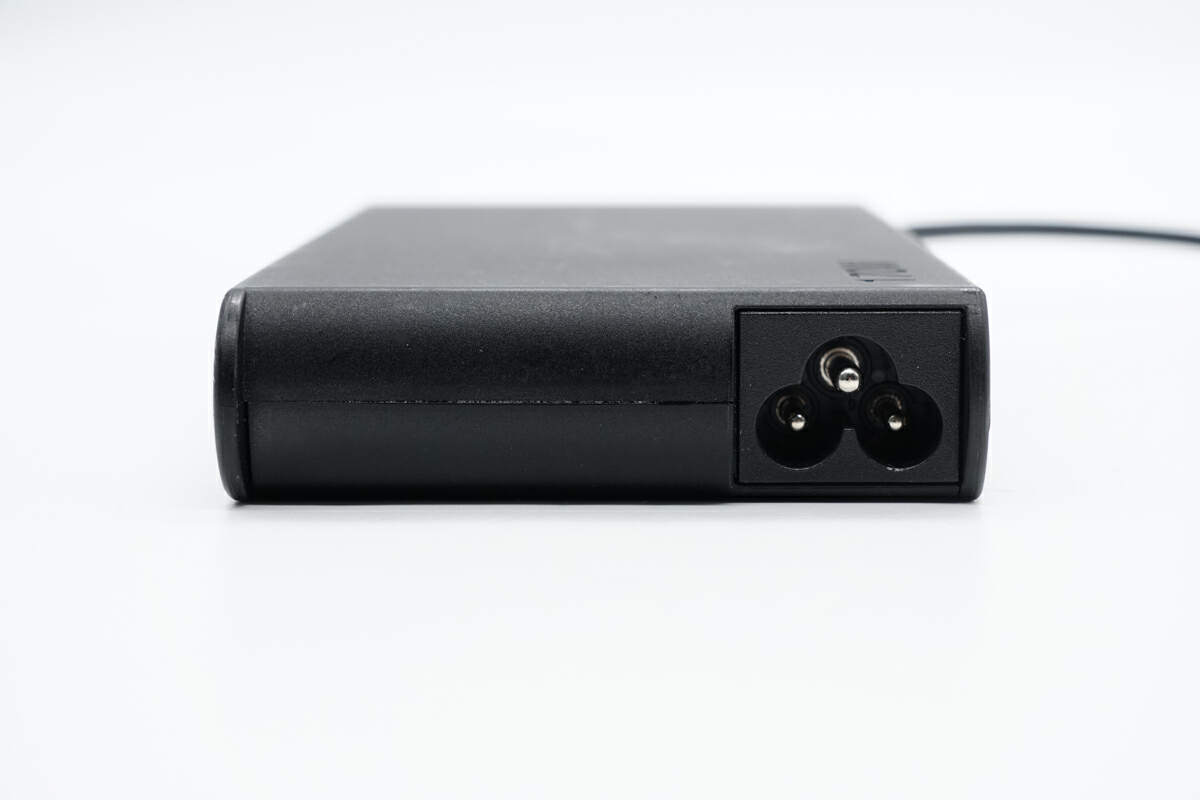
The input socket adopts a three-prong design.
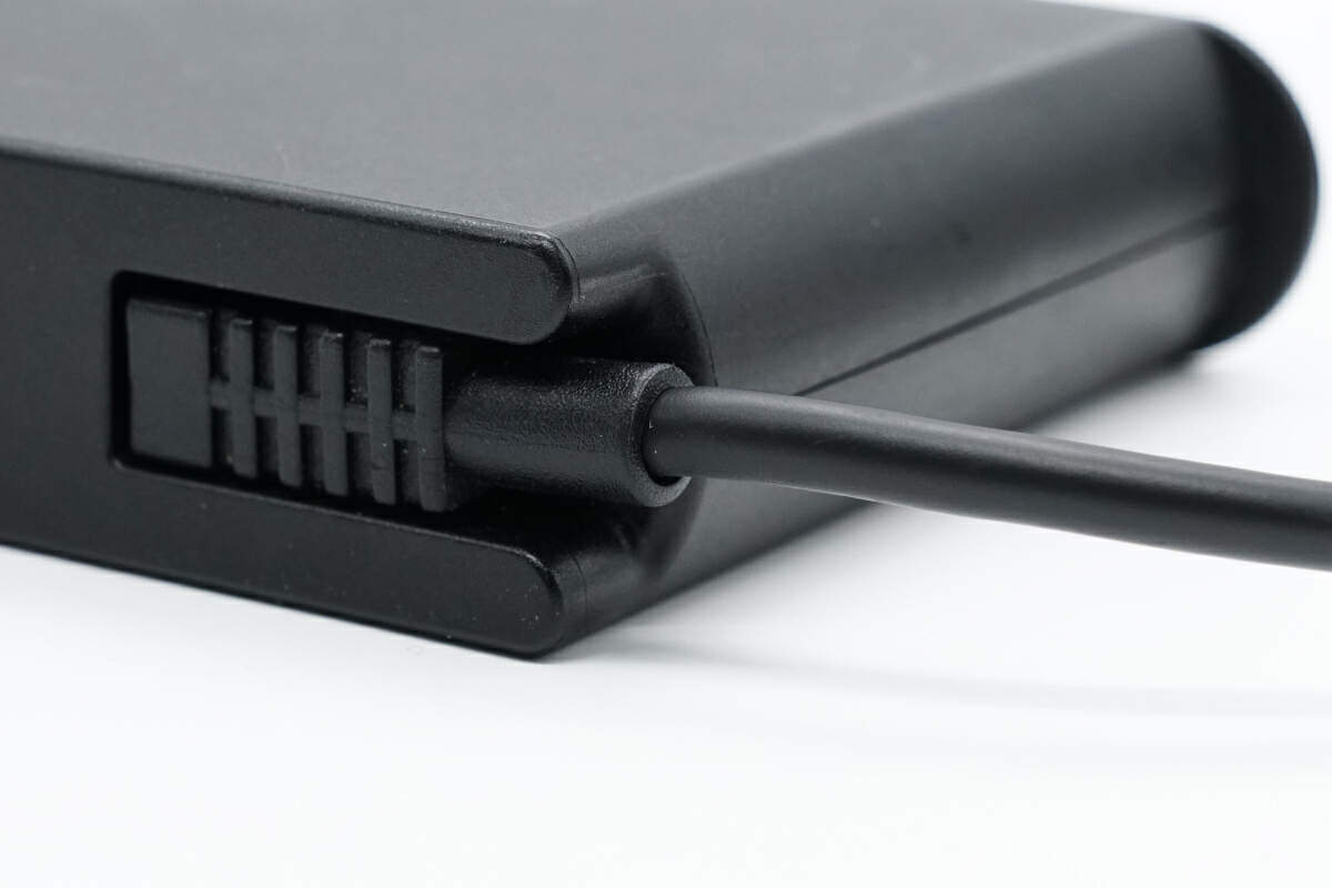
The part connecting the output cable is designed with a groove, which not only protects the cable but also makes it easy to store the adapter.
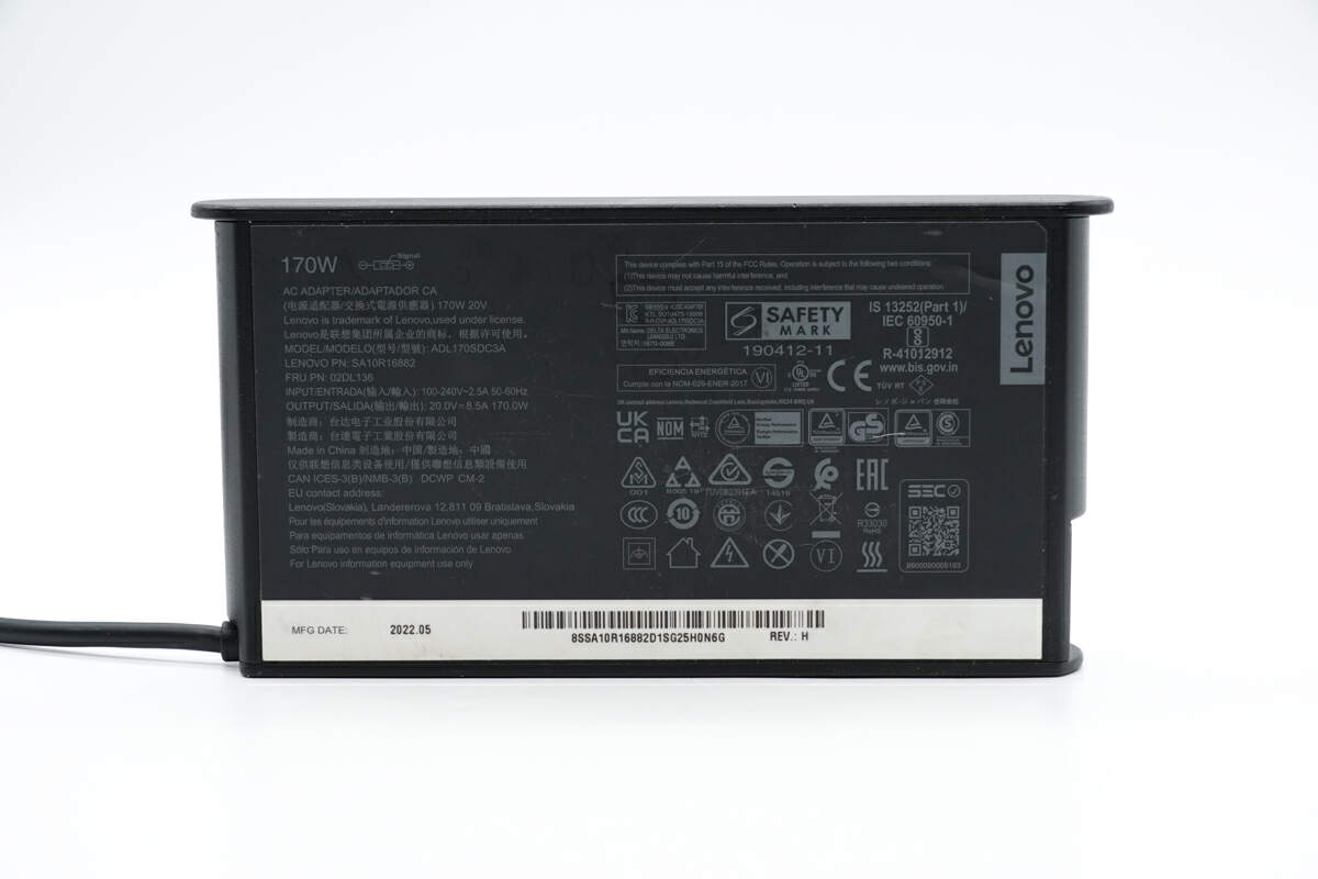
The specs info are on the back of the adapter. It has passed CCC, CE, UKCA, NOM, NYCE, GS, CP, EAC, BIS and other certifications. It can also support input voltage of 100-240V and can be used in most countries and regions.
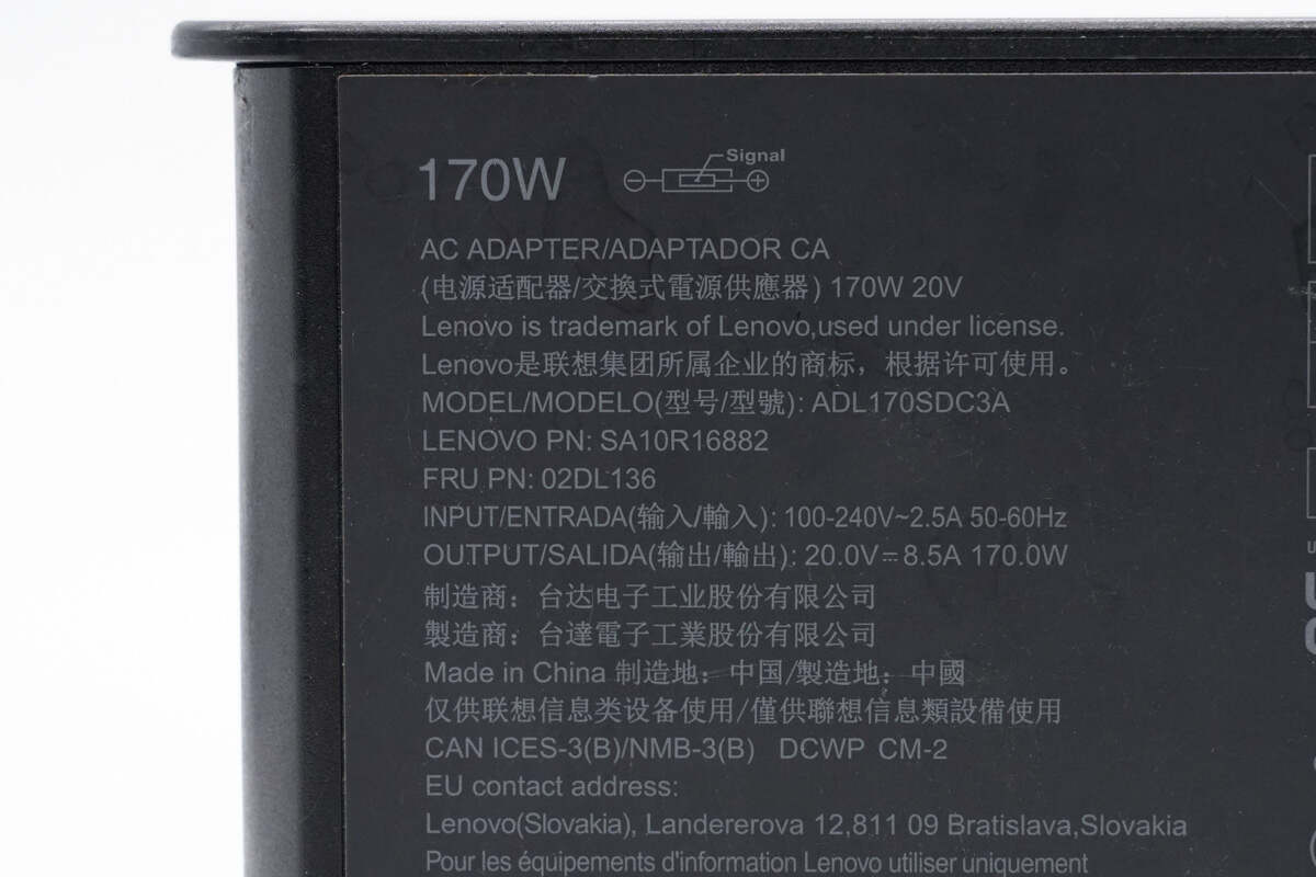
Model is ADL170SDC3A. It can support input of 100-240V~50/60Hz 2.5A. The maximum output power is 20V8.5A 170W.
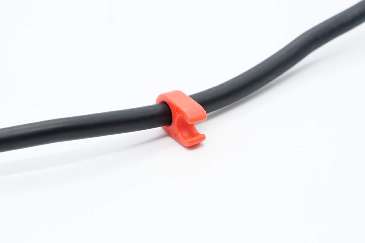
This is an orange plastic clip on the output cable, making it easier for users to organize and carry.
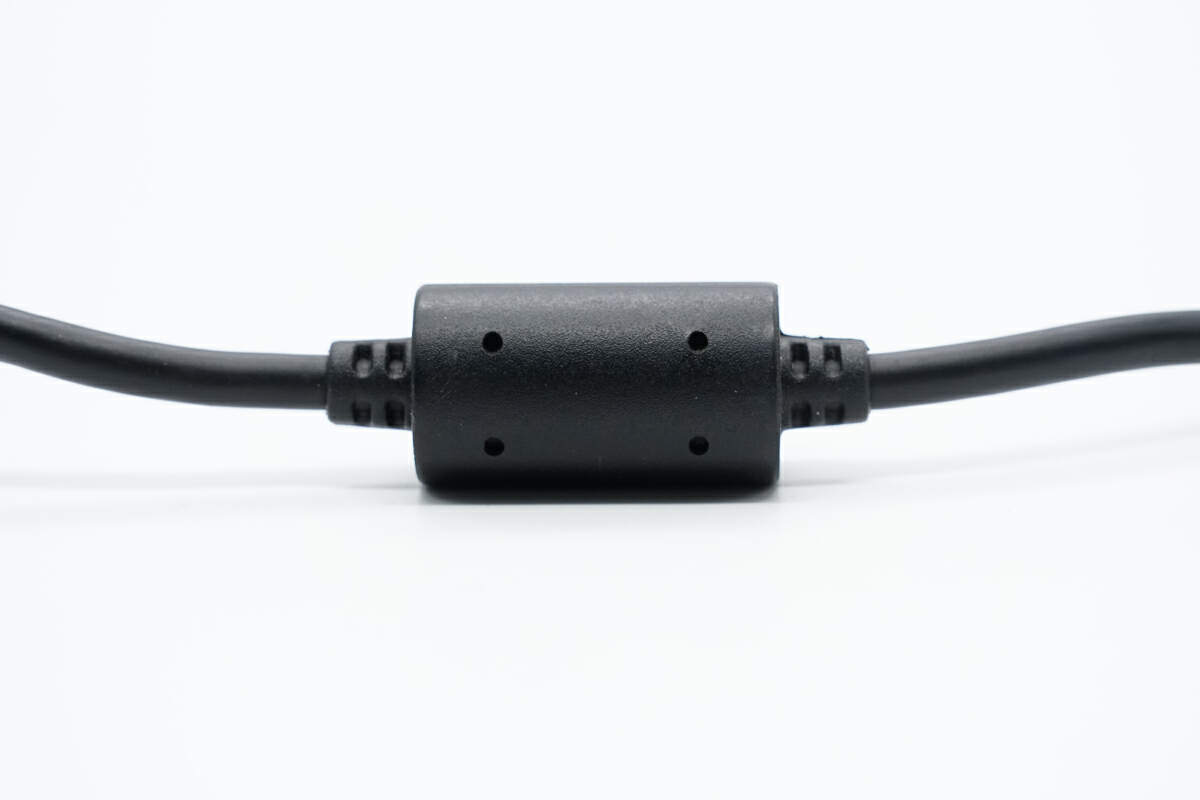
The cable is equipped with a shielded magnetic ring to ensure output.
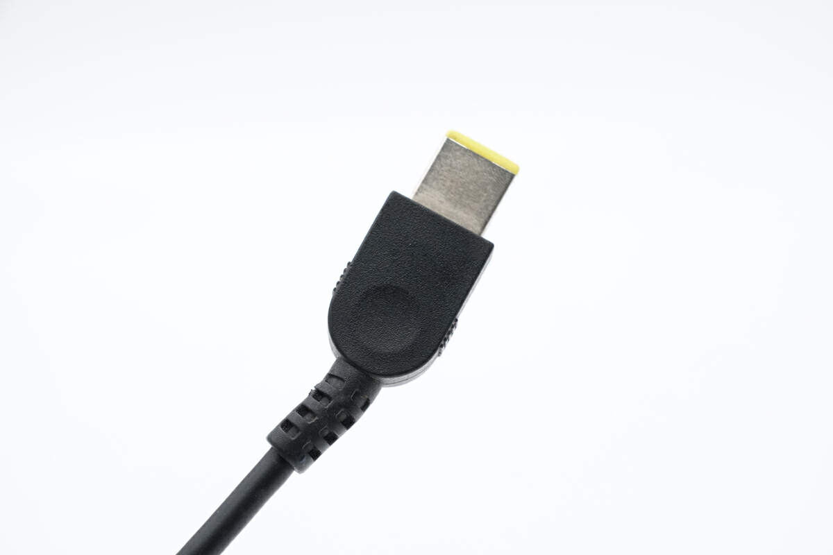
The case of the square connector is equipped with a circular groove to facilitate user plugging and unplugging.
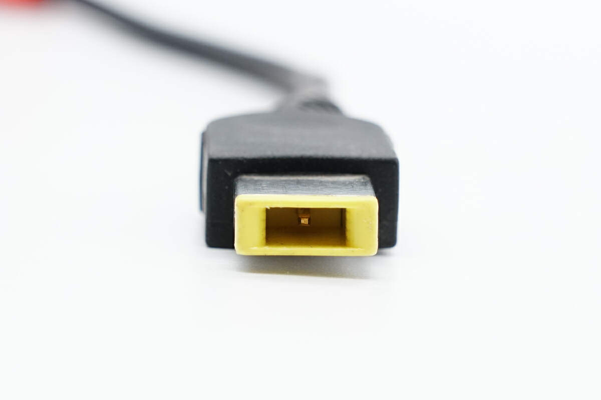
Here is the square connector.
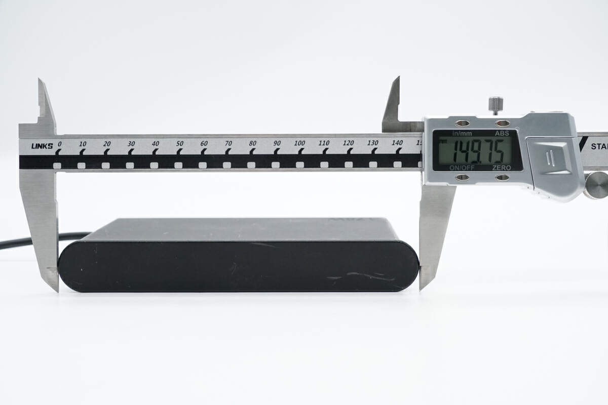
The length of it is about 150 mm (5.91 inches).
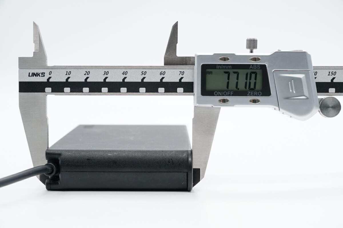
The width is about 77 mm (3.031 inches).
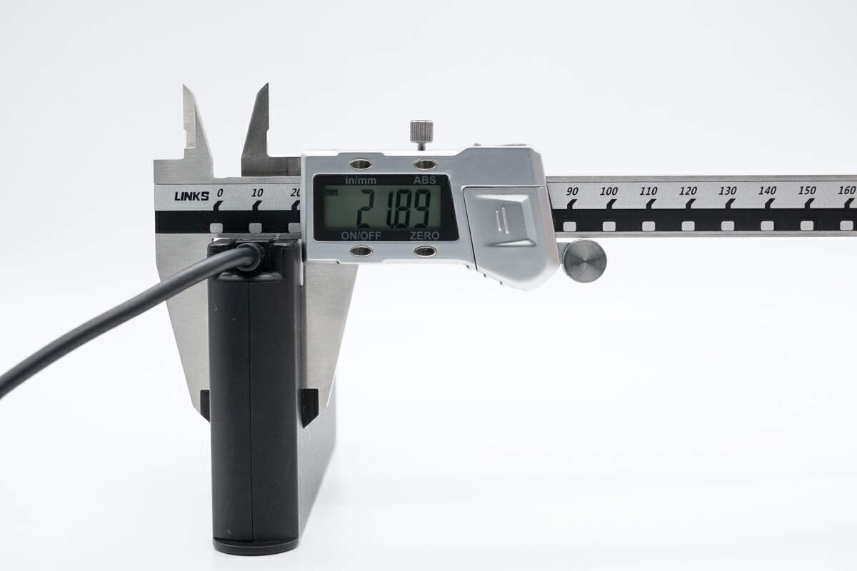
The thickness is about 22 mm (0.87 inches).
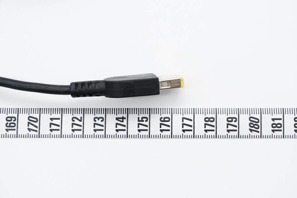
The length of the output cable is about 177 cm (69.69 inches).
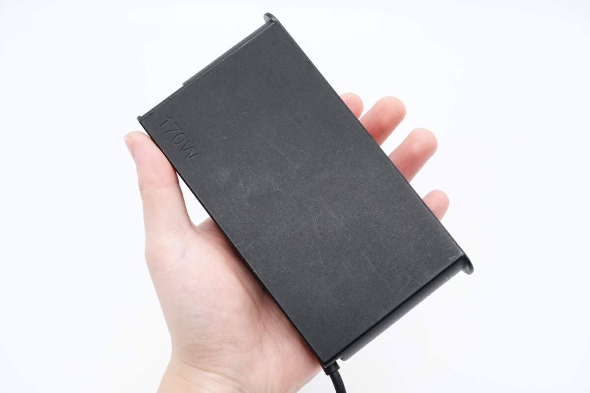
That's how big it is in the hand.
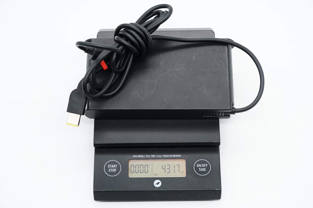
The weight is about 432 g (15.24 oz).
Teardown
After the product's appearance, let's start to take it apart.
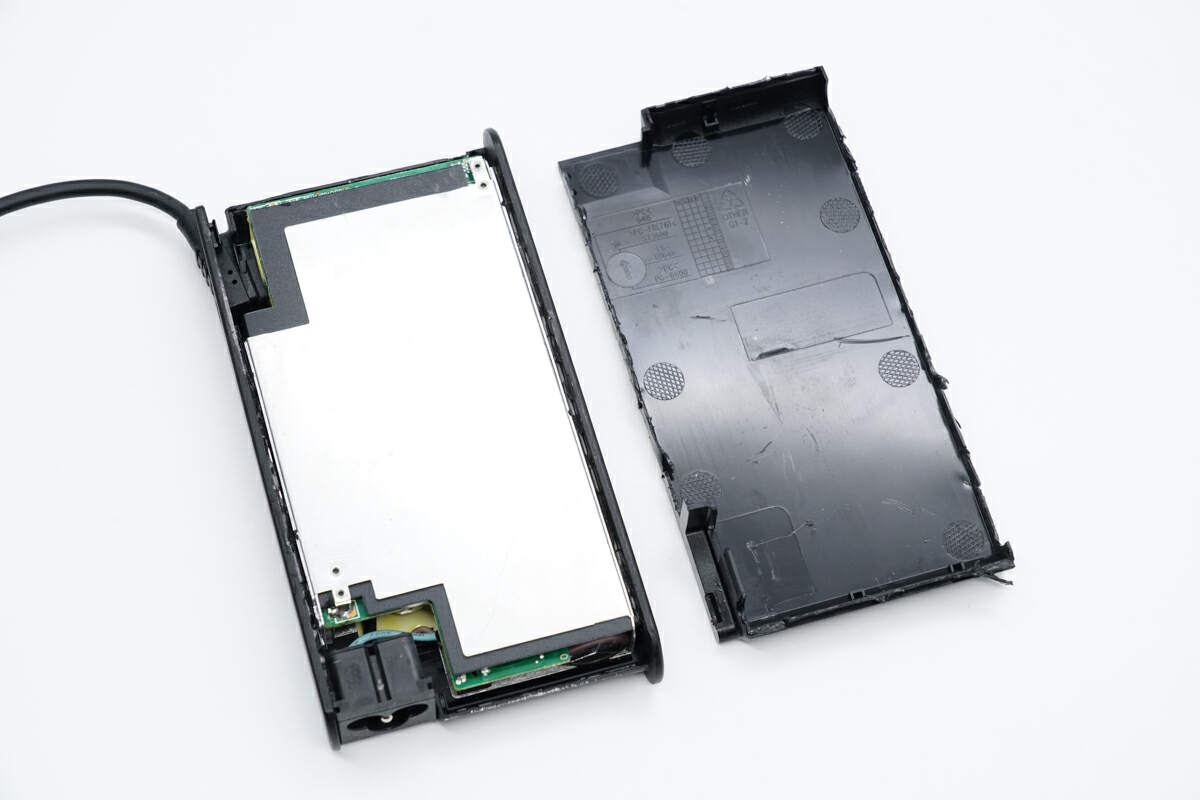
First, use a spudger and a hammer to remove the cover along the gap.
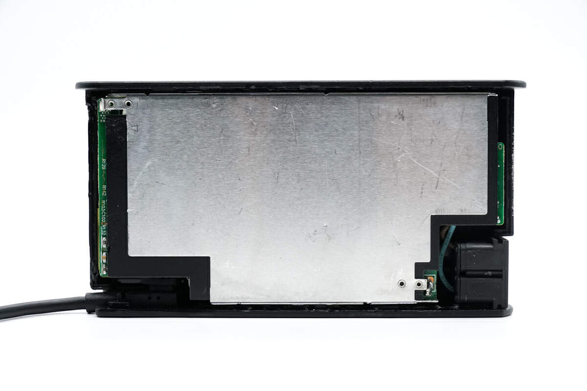
The PCBA module is wrapped with aluminum sheets for heat dissipation.
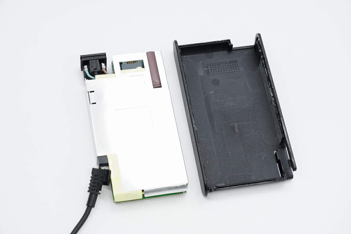
Take out the PCBA module from the case. Metal sheets are pasted on the sides of the case to increase strength.
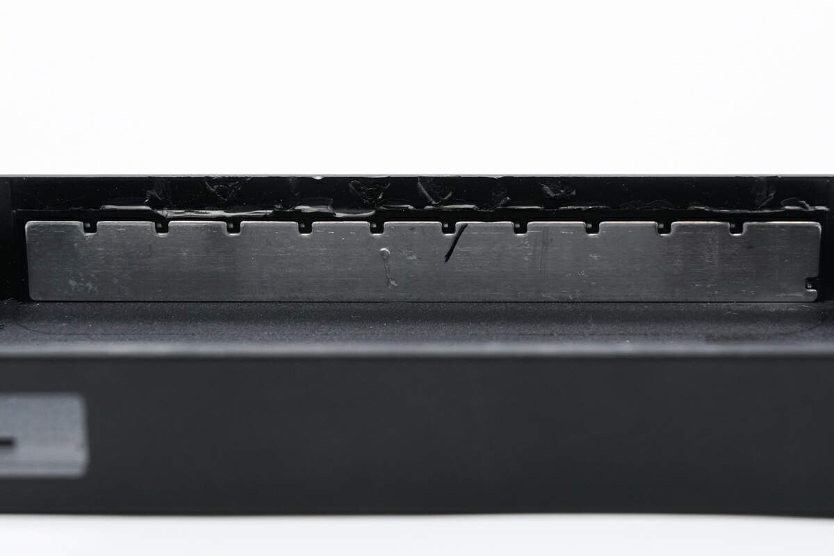
This is the metal sheet on the side.
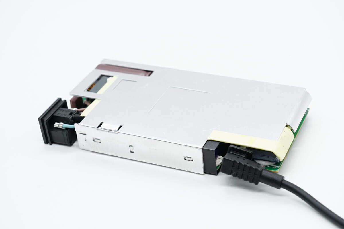
The input socket and output cable are on the same side of the PCBA module.
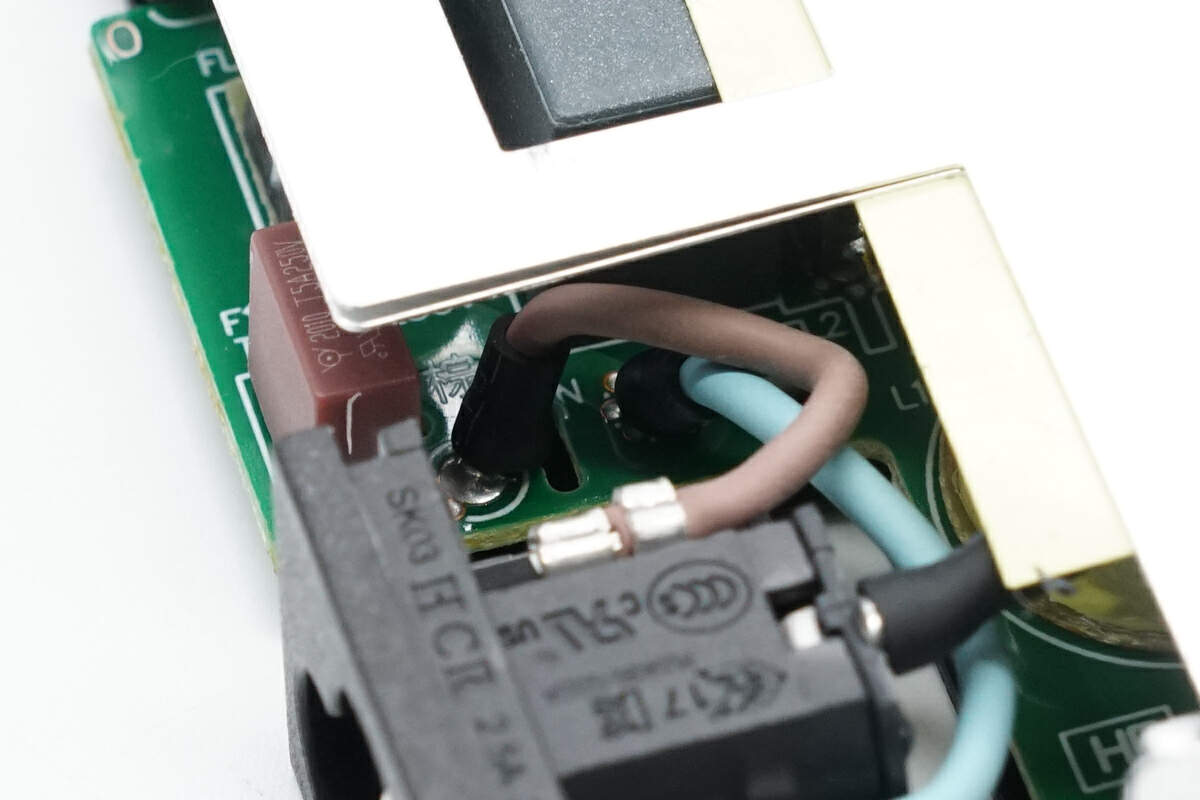
The AC input socket is connected via soldering.
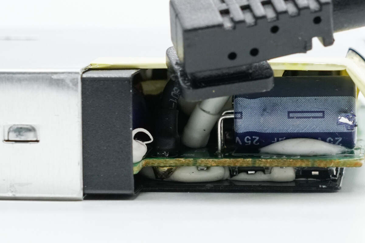
The DC output cable is also connected by soldering.
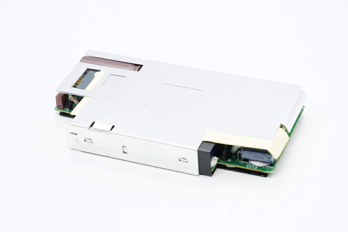
The aluminum heat sinks are fixed with clips.
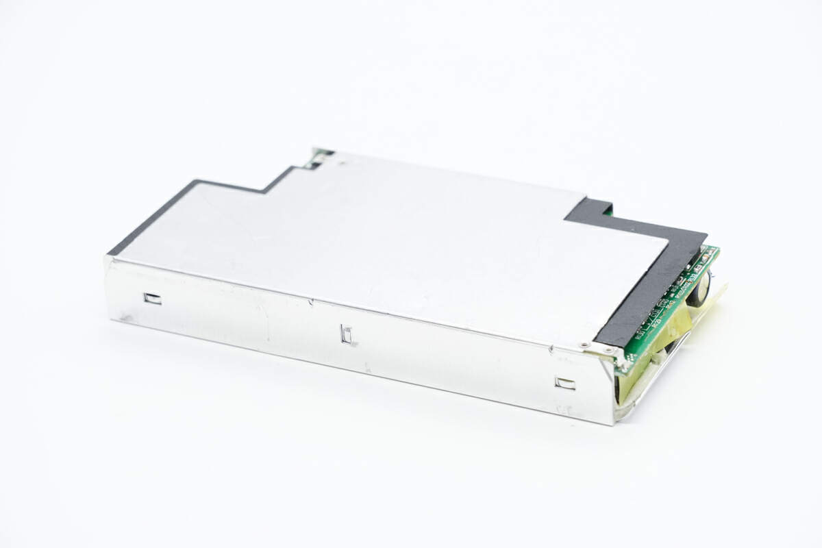
The other side is also fixed with clips and is insulated from the PCBA module by mylar sheets.
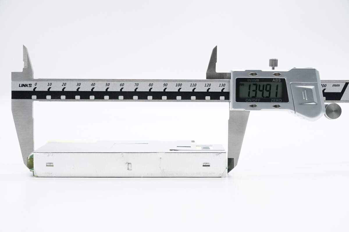
The length of the PCBA module is about 135 mm (5.31 inches).
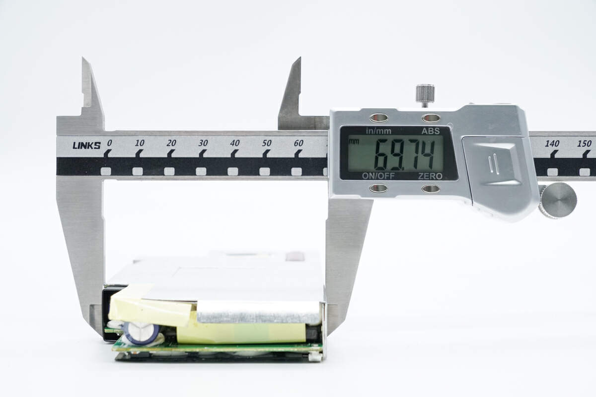
The width is about 70 mm (2.76 inches).
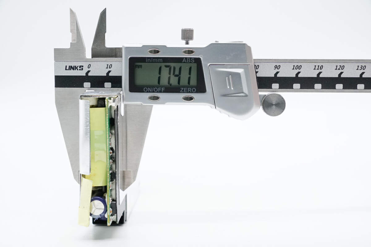
The thickness is about 17 mm (0.67 inches).
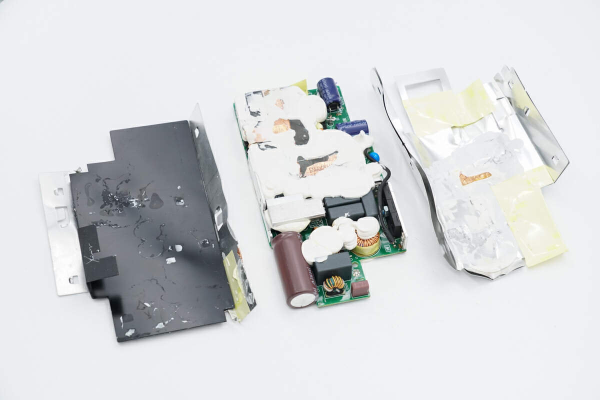
Remove the heat sink and take out the PCBA module. The Mylar sheet on the heat sink is used for insulation, and the componentsare filled with potting compound for heat dissipation.
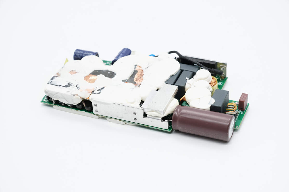
The PCBA module is fixed with potting compound.
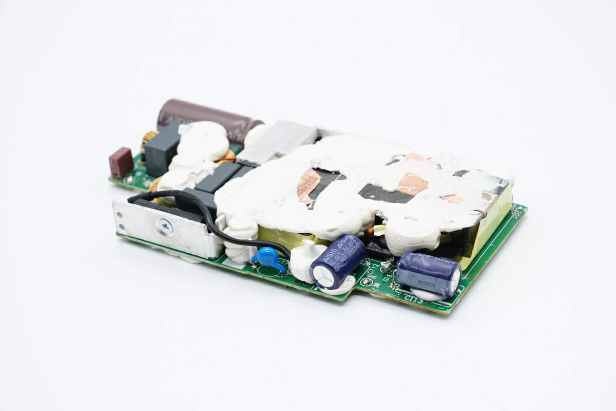
The filter capacitors are also fixed with potting compound.
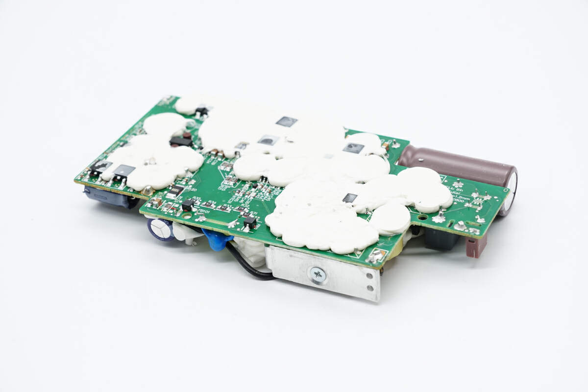
The back of the PCBA module is filled with potting compound for heat dissipation.
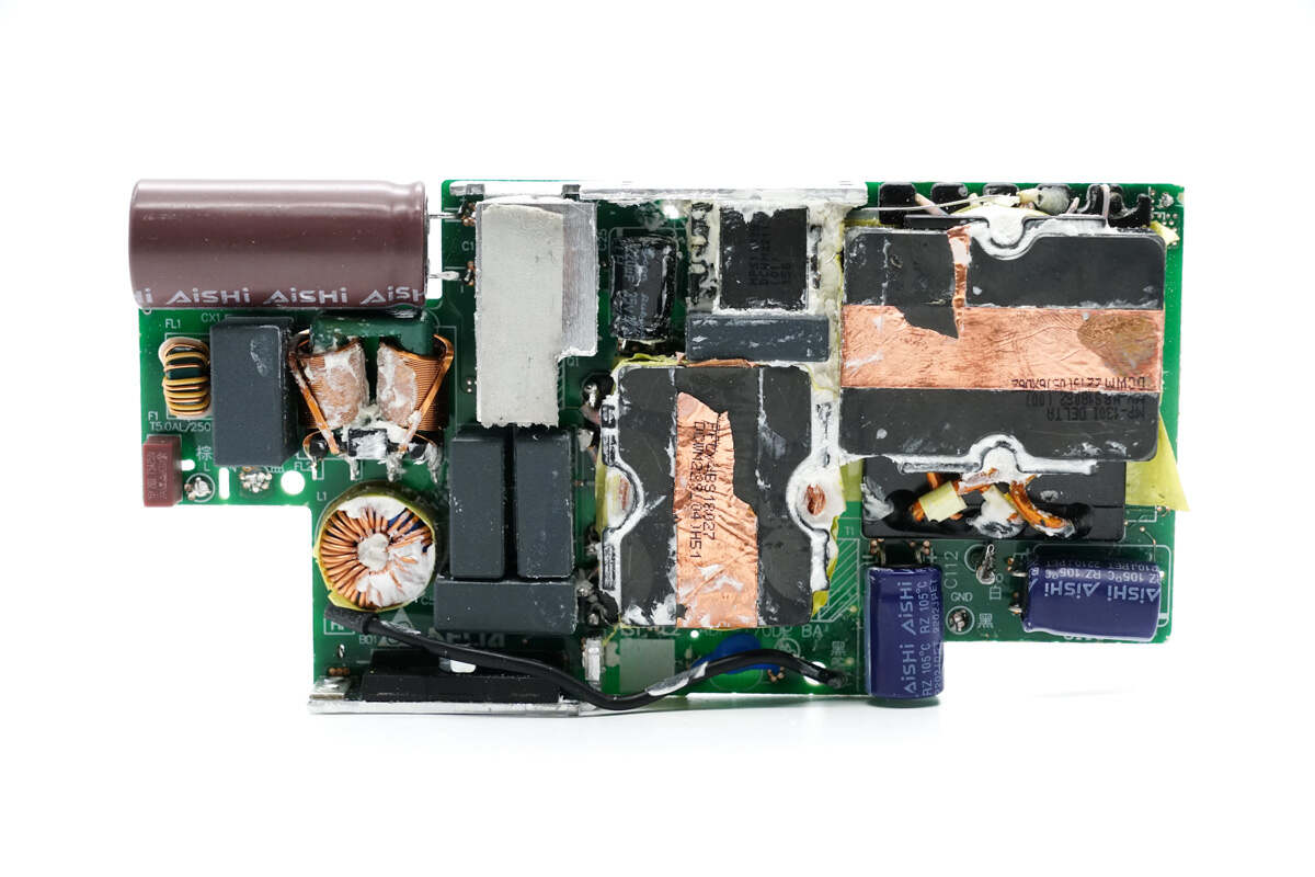
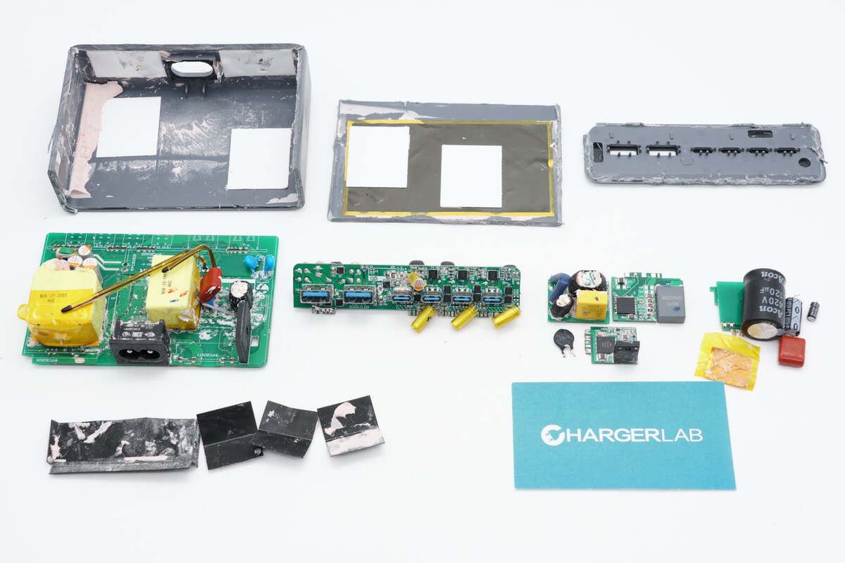
Clean off the potting compound on both sides of the PCBA module. There are fuse, common mode choke, safety X2 capacitor, inductor, bridge rectifier, capacitor, and transformer on the PCBA module.
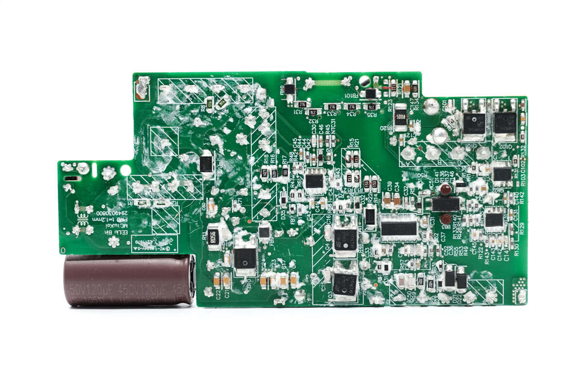
There are PFC controller, PFC rectifier, LLC controller, optocoupler, synchronous rectifier controller, two synchronous rectifiers, and output protection chip on the back of the PCBA module.
ChargerLAB found that it adopts PFC and LLC circuits with fixed output voltage. Both the PFC circuit and the LLC circuit use independent controllers.
Next, we will take a look at each component starting from the input end.
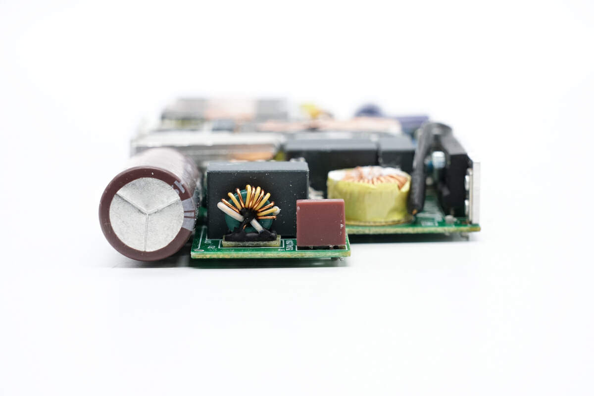
The fuse, common mode choke, safety X2 capacitor, filter capacitor, differential mode chocks, and bridge rectifier are at the input end of the PCBA module.
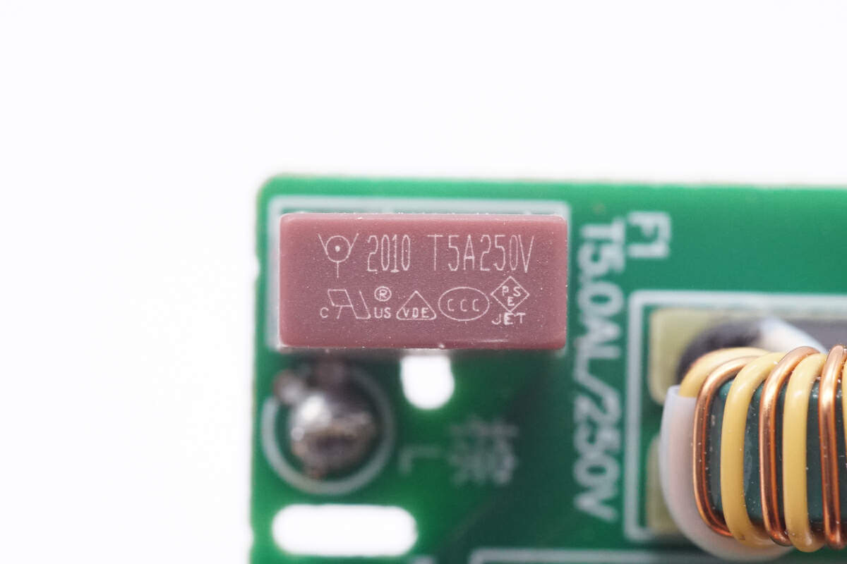
The input fuse is from WalterFuse. 5A 250V.
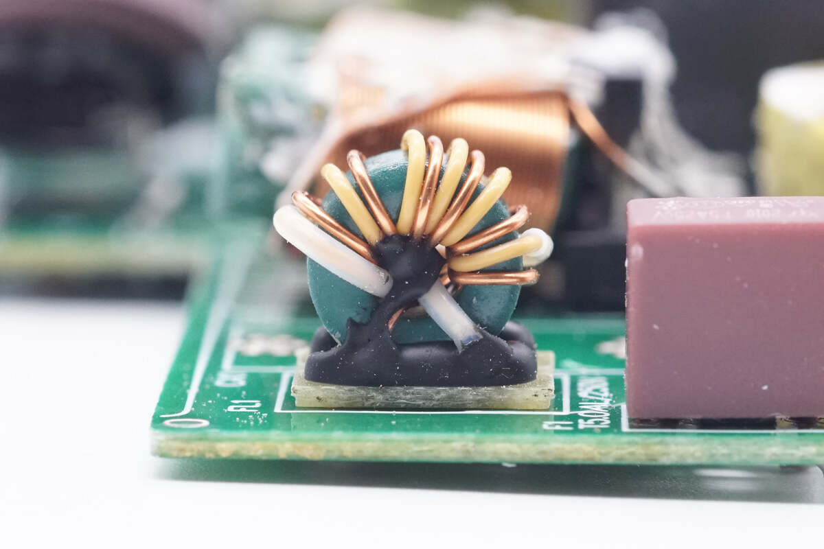
The common mode choke is wound with magnet and insulated wires, and it's also insulated with bakelite.
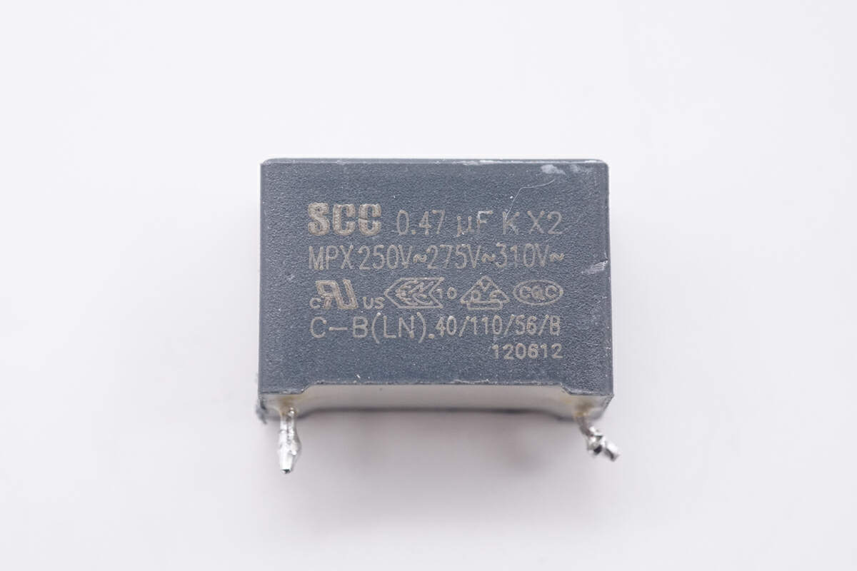
The safety X2 capacitor is from Strong Components. 0.47μF.
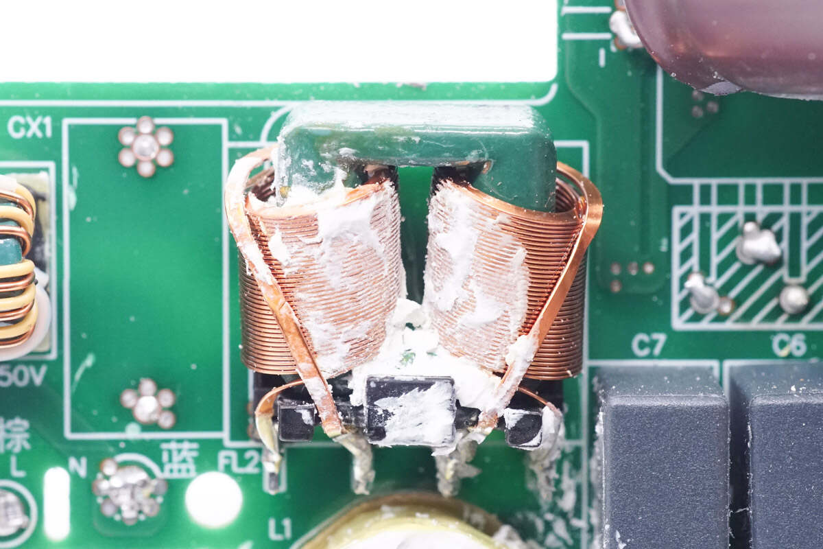
The second common mode choke is wound with flat copper wire.
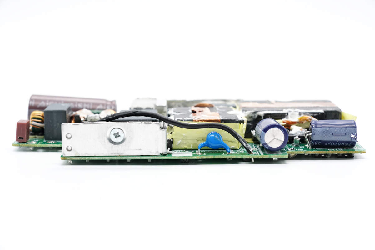
The heat sink of the bridge rectifier, Y capacitor, and electrolytic capacitor for output filtering are fixed on the side of the PCBA module.
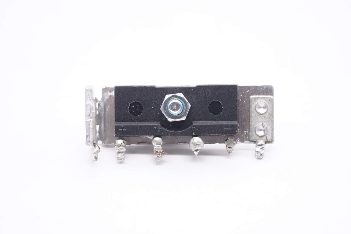
The bridge rectifier is fixed on the heat sink with a screw.
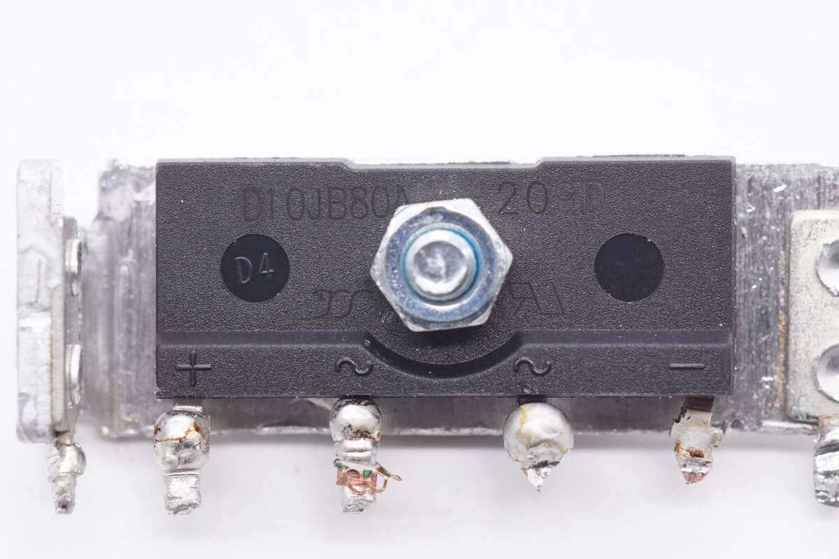
The bridge rectifier is from Yangjie. Model is D10JB80A. 10A 800V.
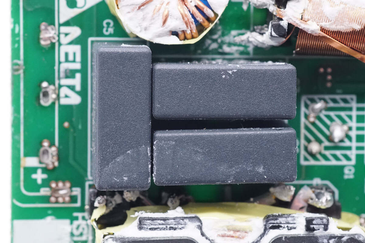
These are three film capacitors.
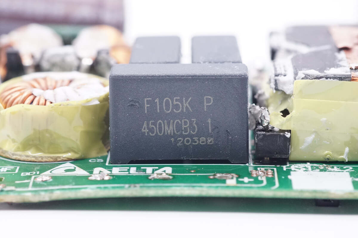
The specification of the film capacitor is 1μF 450V.
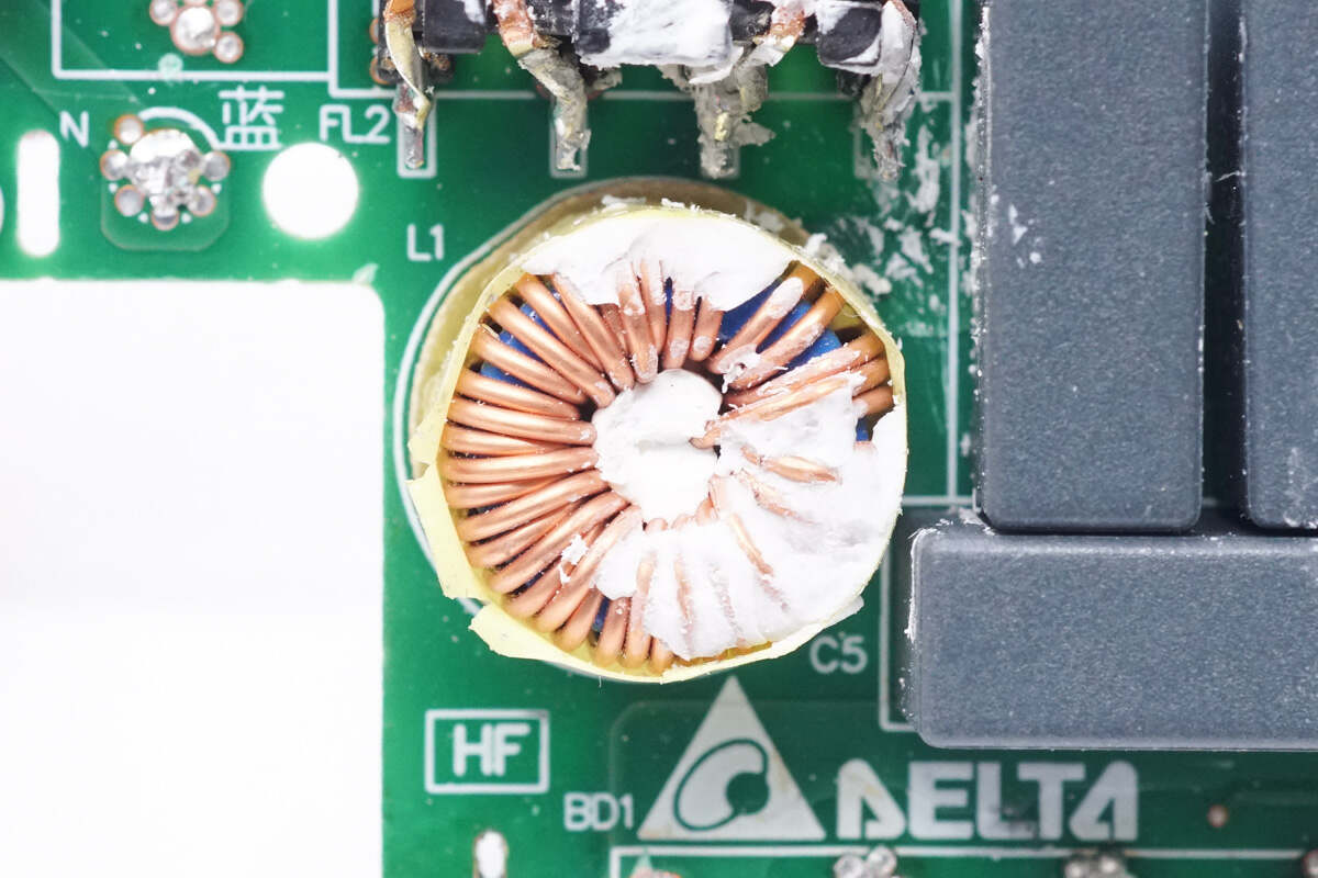
The filter inductor is wounded with magnetic ring and insulated by tape.
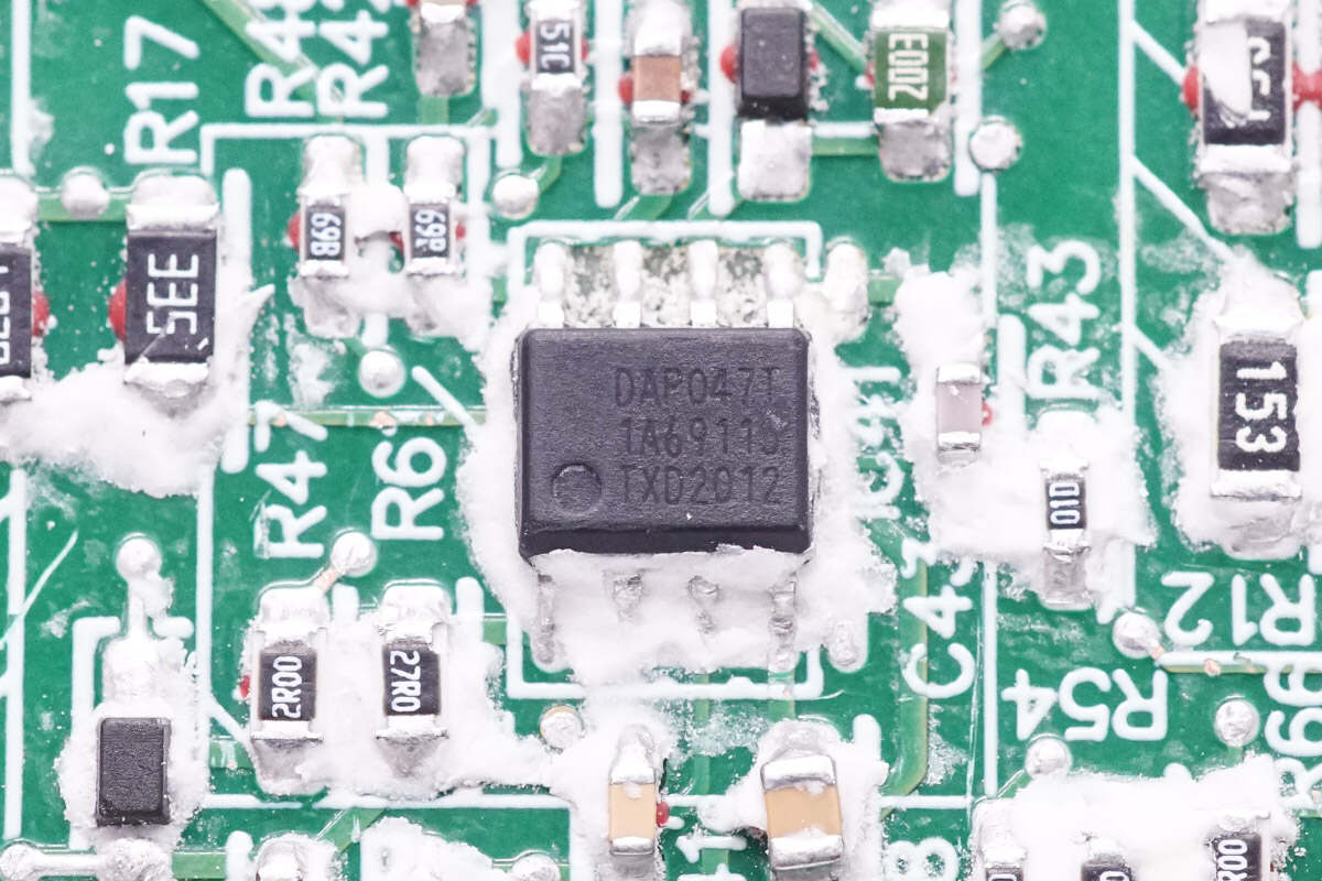
The PFC controller is marked with DAP047T.
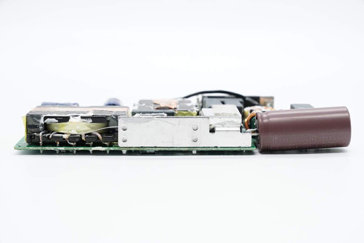
The filter capacitor, heat sink of the PFC MOSFET, and LLC transformer are on the other side of the PCBA module.
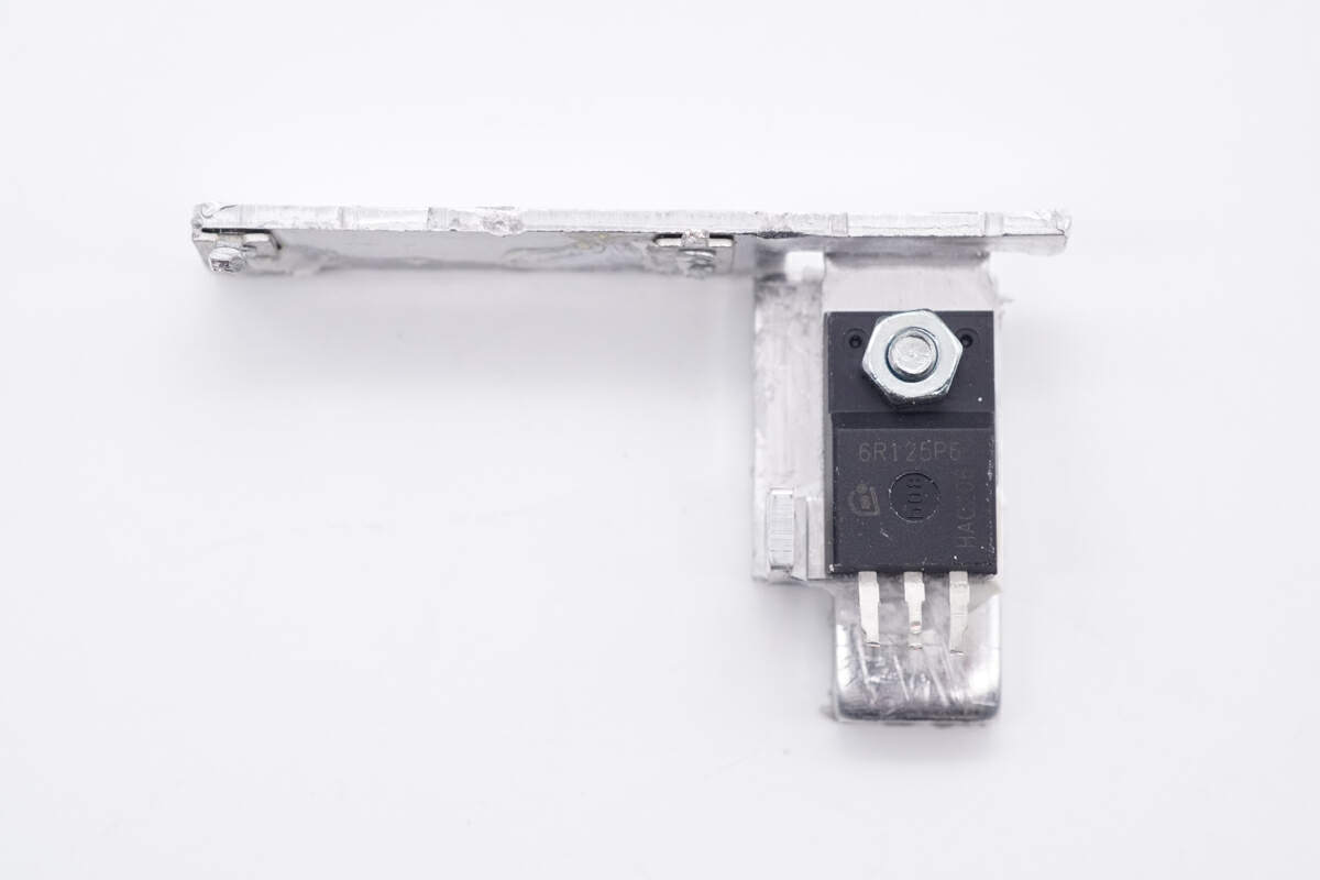
The PFC MOSFET is fixed to the heat sink with a screw.
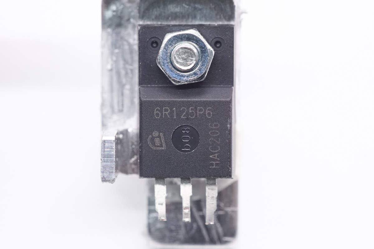
The PFC MOSFET is from Infineon and adopts TO-220FP package. Model is IPA60R125P6. 650V 125mΩ.
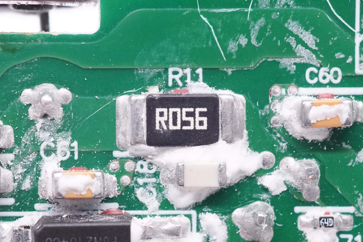
The sampling resistor is used to detect the current of the PFC MOSFET. 56mΩ.
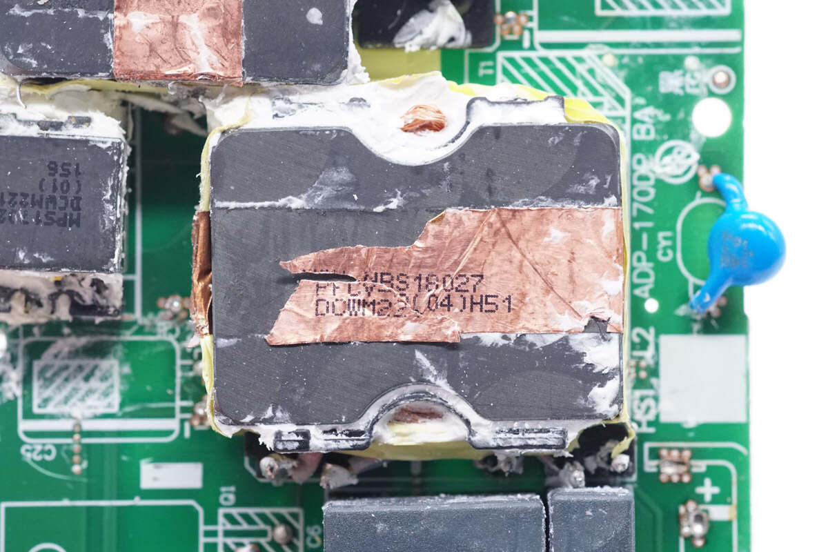
The magnetic core of the PFC boost inductor is wrapped with copper foil for shielding.
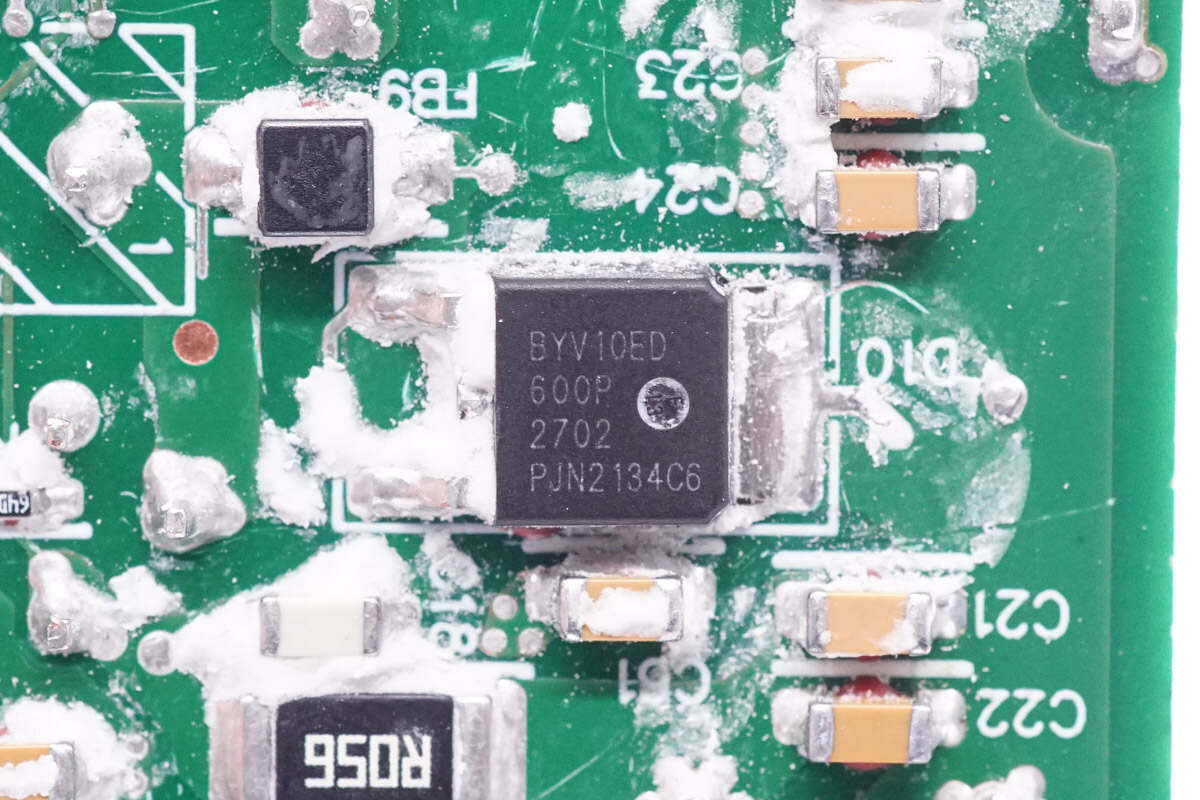
The PFC rectifier is from RePower and adopts DPAK package. Model is BYV10ED-600P. 600V 10A.
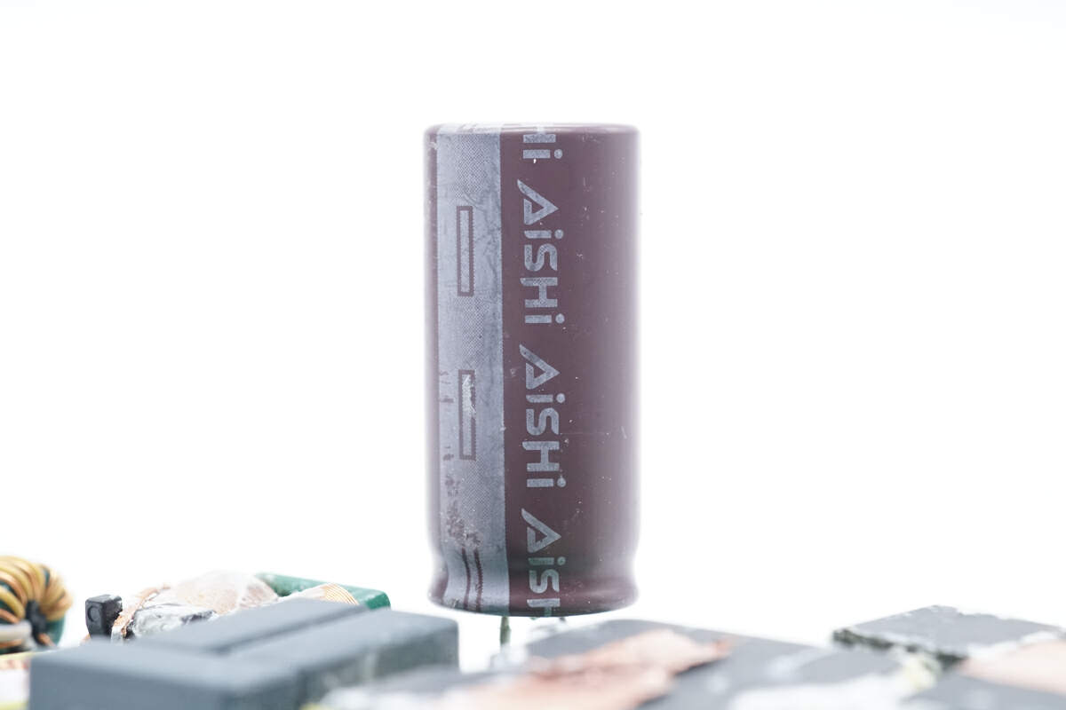
This electrolytic capacitor for input filtering is from AiSHi.
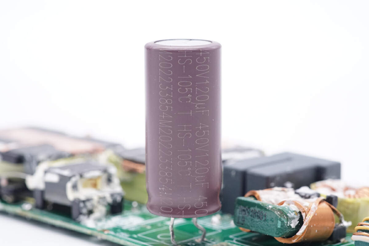
Its specification is 450V 120μF.
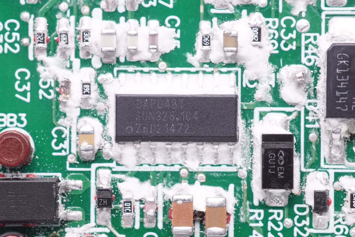
The LLC controller is marked with DAP048T.
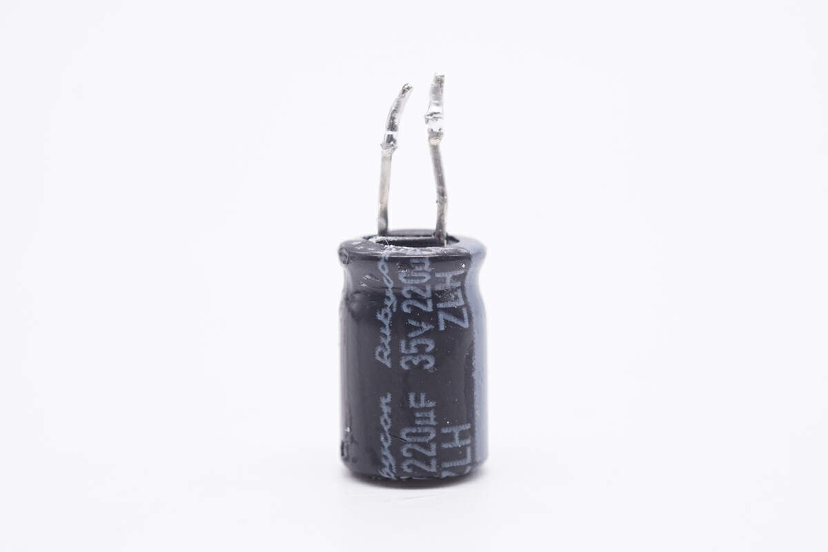
The filter capacitor used to power the master control chip is from Rubycon ZLH series. 35V 220μF.
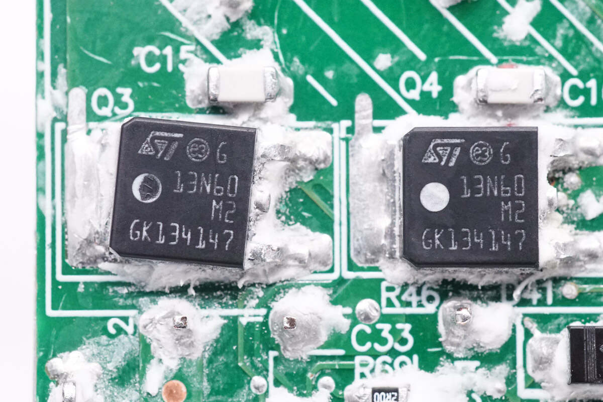
The LLC MOSFET is from Infineon and adopts DPAK package. Model is STD13N60M2. 650V 380mΩ.
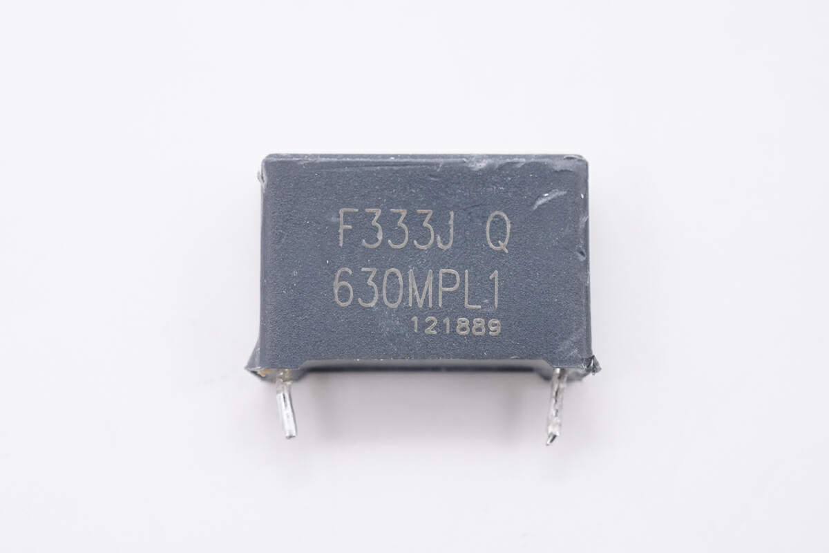
The specification of the resonant capacitor is 0.033μF 630V.
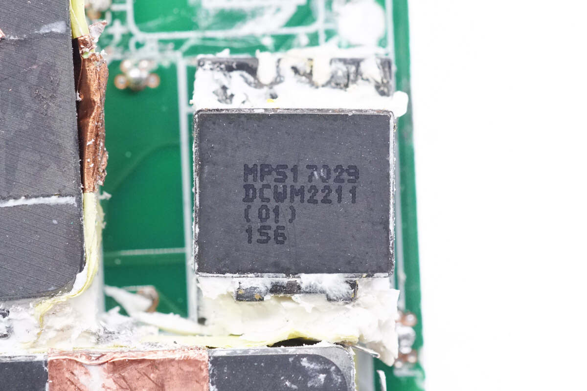
There is the resonant inductor.
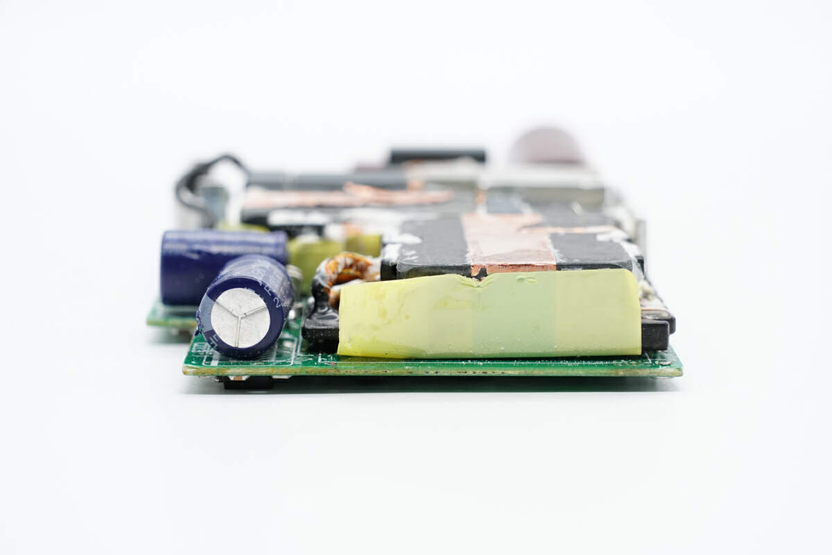
This side of the PCBA module has the transformer and capacitor for output filtering.
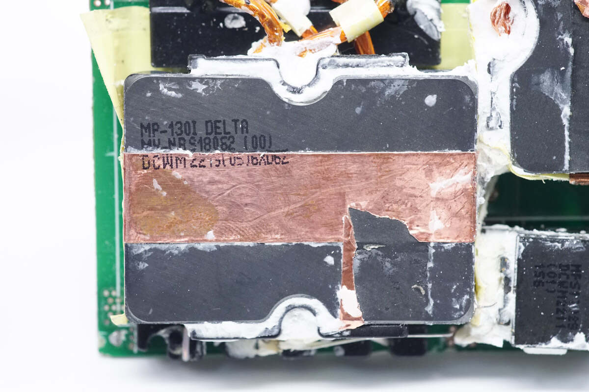
The magnetic core of the LLC transformer is wrapped with copper foil for shielding.
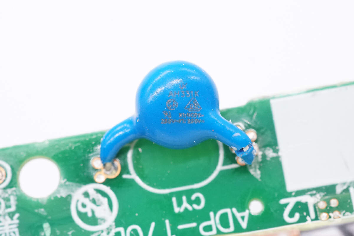
Here is the blue Y capacitor.
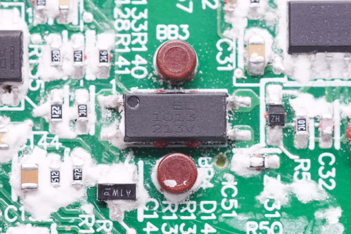
The optocoupler used for output voltage feedback is from Everlight. Model is EL1013.
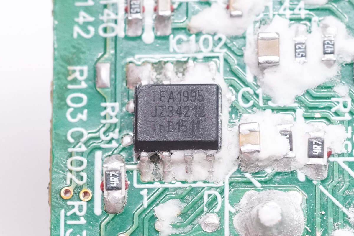
The synchronous rectifier controller is from NXP. It has two built-in independent synchronous rectification drivers for the LLC circuit. It supports a working voltage of 38V and PD3.1. Model is TEA1995.
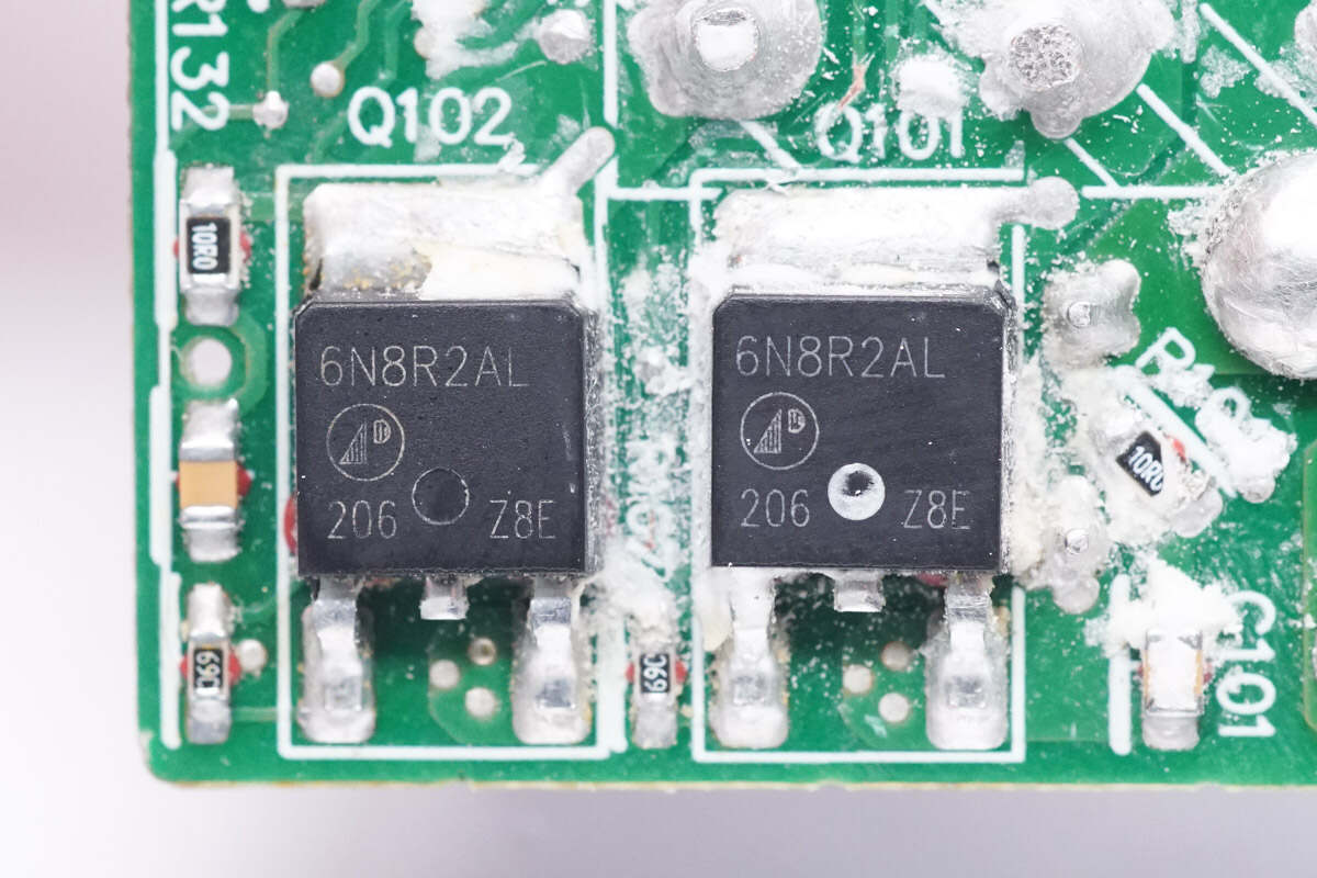
The synchronous rectifier is from APEC and adopts TO-252 package. Model is AP6N8R2ALH. 60V 8.2mΩ.
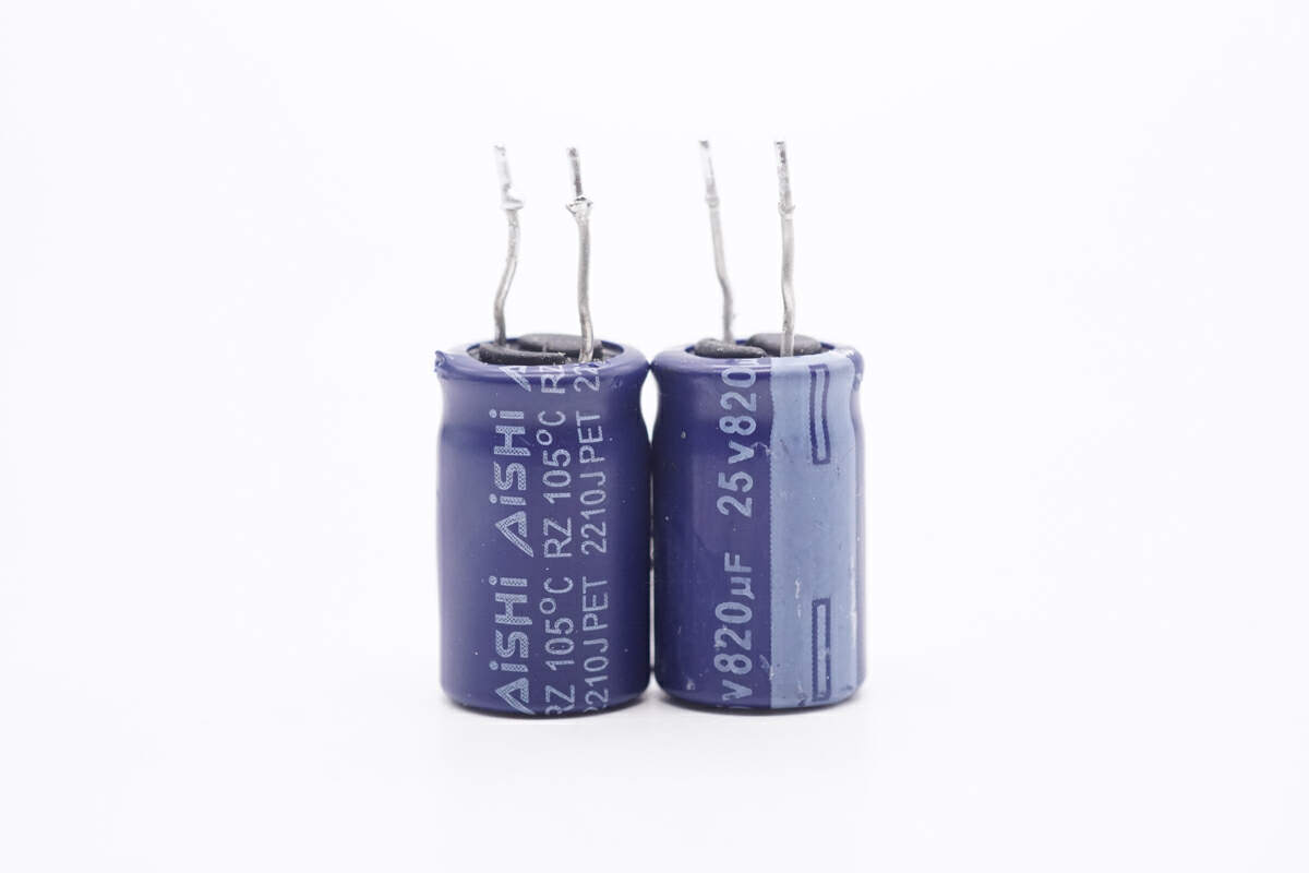
These two electrolytic capacitors for output filtering are from AiSHi. 25V 820μF.
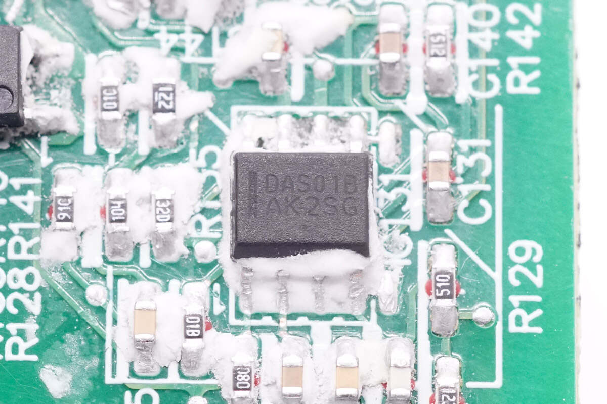
The output protection chip is marked with DAS01B.
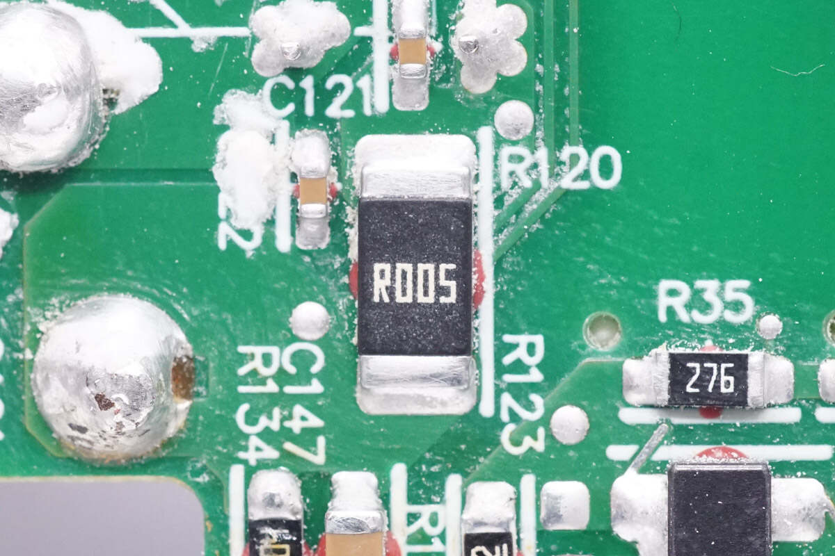
The sampling resistor is used for output overcurrent protection. 5mΩ.
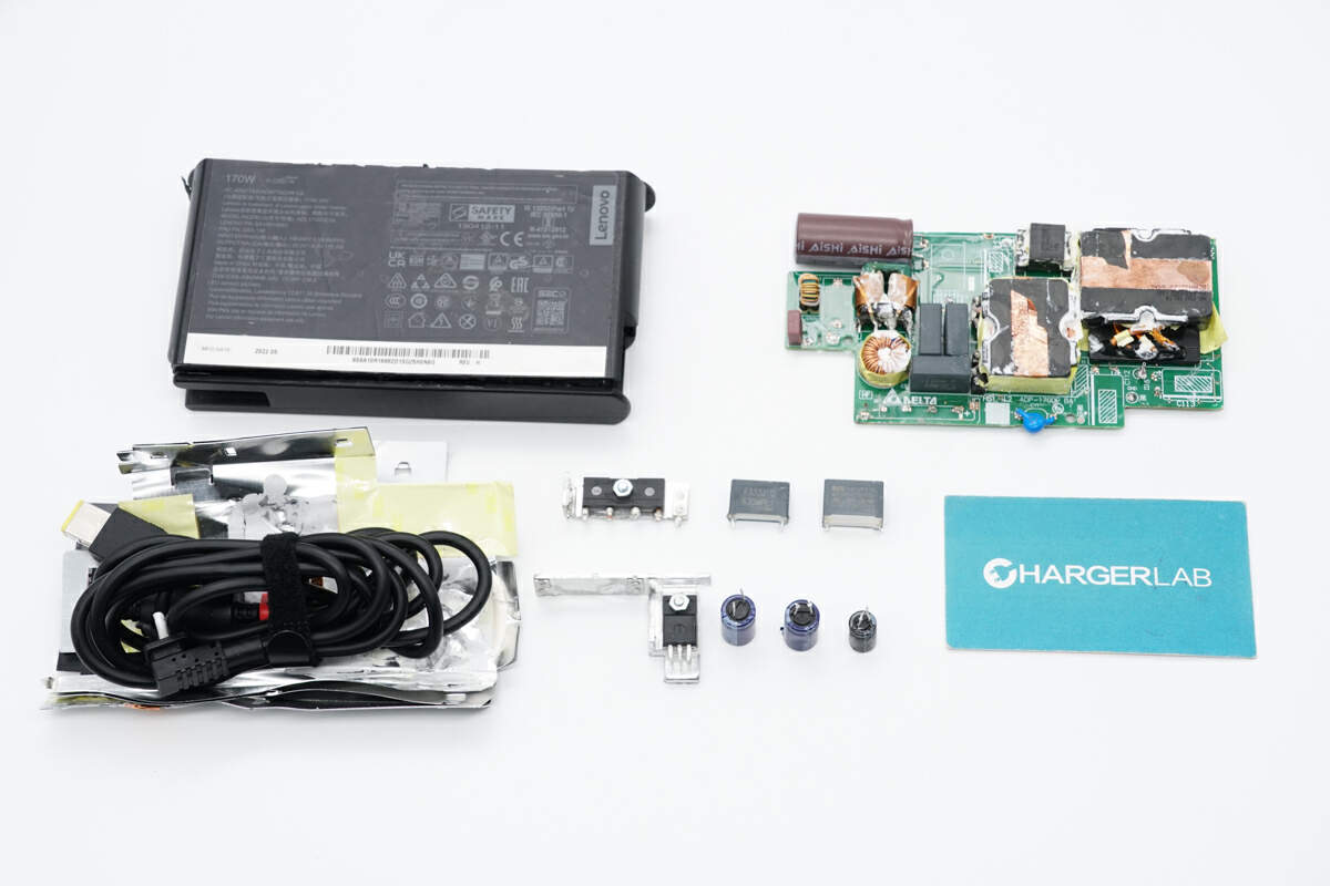
Well, those are all components of the Lenovo 170W AC Power Adapter.
Summary of ChargerLAB
Compared with Lenovo's old Power Adapter, it is thinner and smaller. The power cord features a 3-prong design and is detachable. The output power can be up to 170W.
After taking it apart, we found it adopts PFC and LLC circuits with fixed output voltage. The synchronous rectifier controller is from NXP and the PFC MOSFET is from Infineon. The PCBA module is wrapped with aluminum sheets for heat dissipation, and the bridge rectifier and PFC MOSFET are also equipped with heat sinks. The internal components are fixed with potting compound, and the workmanship is solid. It can meet the charging needs of high-power laptops.
Related Articles:
1. Teardown of DELL 165W PD3.1 GaN Power Adapter (LA165PM210)
2. DJI 100W Dual USB-C GaN Power Adapter Review
3. Raspberry Pi 15W USB-C Power Adapter (KSA-15E-051300HU)

