Introduction
ChargerLAB introduced the EHOM EP1650 Portable Power Station before. Its battery capacity is 1024Wh and the weight is about 13.7kg (30.2 pounds). It can support an output power of up to 1650W. The peak output power is 2700W, which is pure sine wave output.
The AC input power is 1200W. The DC input supports a voltage of 11-55V, the maximum current is 8A, and the maximum power is 400W. The DC input supports charging with solar panels. The DC input from the car charger supports 12/24V, and the default current is 8A.
It is equipped with three USB-A ports that support 18W and two USB-C ports that support 100W. The car port can support 12V8A 96W. It has an LCD to display the remaining power, input and output power, and available time.
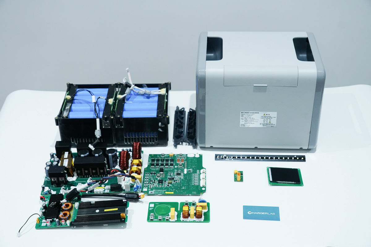
Next, we will take it apart to see its internal components and structure.
Product Appearance
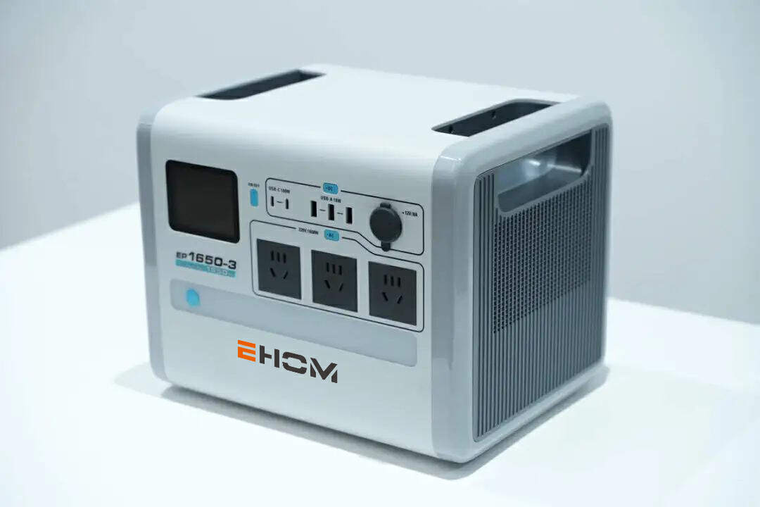
It has a matte one-piece shell, and the color of it is gray and white. The shell can protect it from dropping from a height of even 1 meter.
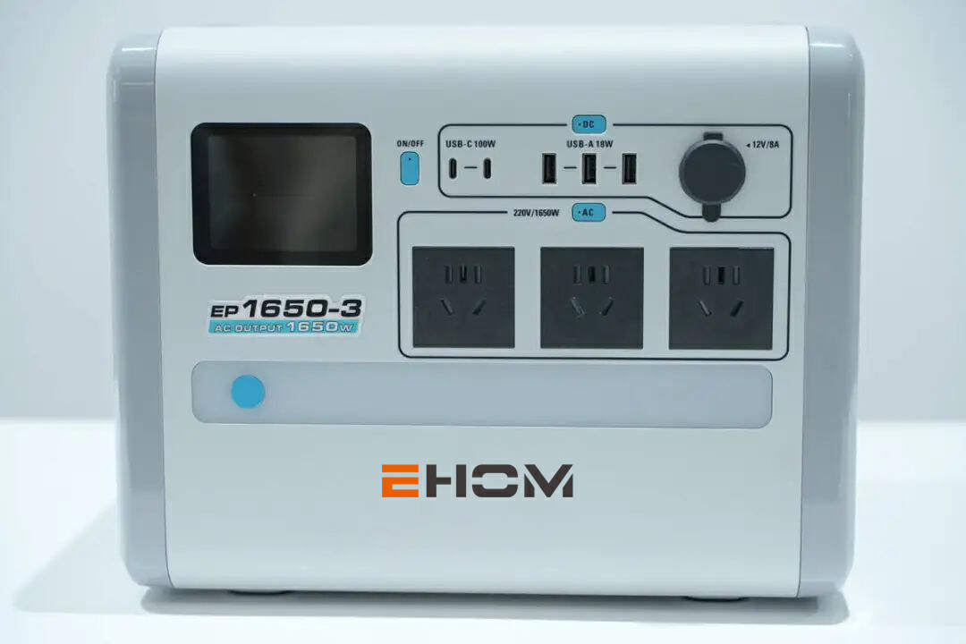
The front of it is equipped with an LCD, a car port, five USB ports, three AC outlets, and a light. It can meet the power needs of most electrical appliances.
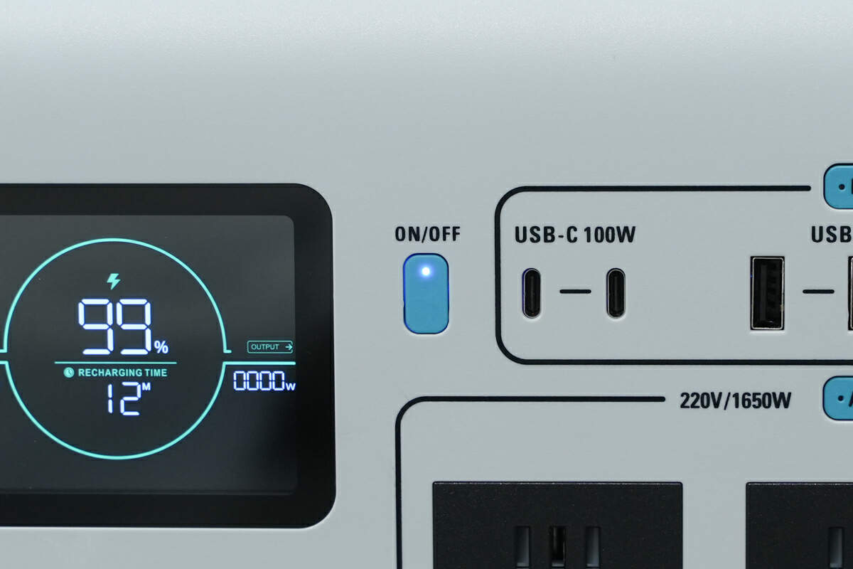
In addition to the main power button, it is also equipped with independent switch buttons for the DC module and AC module. Each button is equipped with an indicator light that lights up when turned on. This design makes it easier for users to confirm the device status.
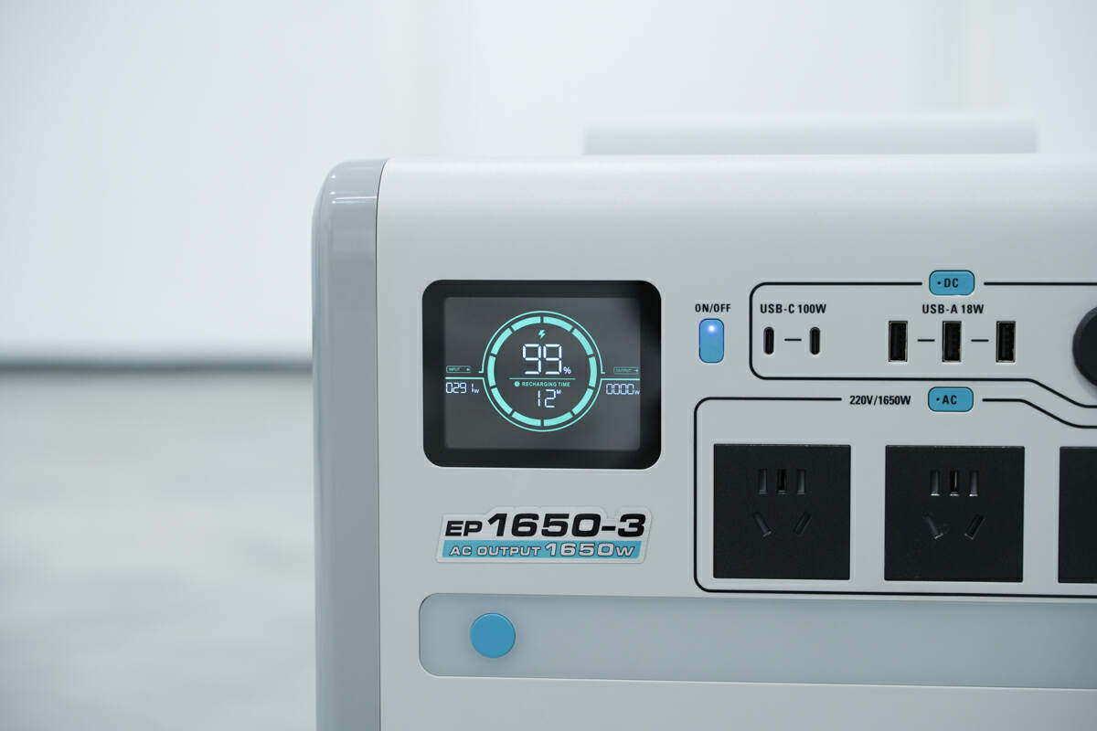
After turning on the main power button, the LCD will display the remaining power, input and output power, and available time. It can also display Bluetooth, AC output, USB-C/USB-A output, DC output, high/low temperature warning, battery failure warning, etc.
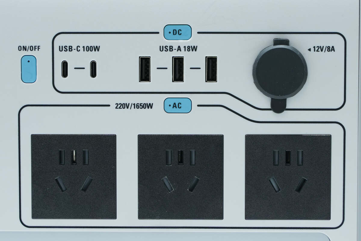
The DC module is equipped with two USB-C ports, three USB-A ports, and a car port. It can meet the simultaneous fast-charging needs of multiple devices such as phones, tablets, and laptops.
The AC outlet can provide a voltage of 220V AC with a rated power of 1650W and a peak output power of up to 2700W.
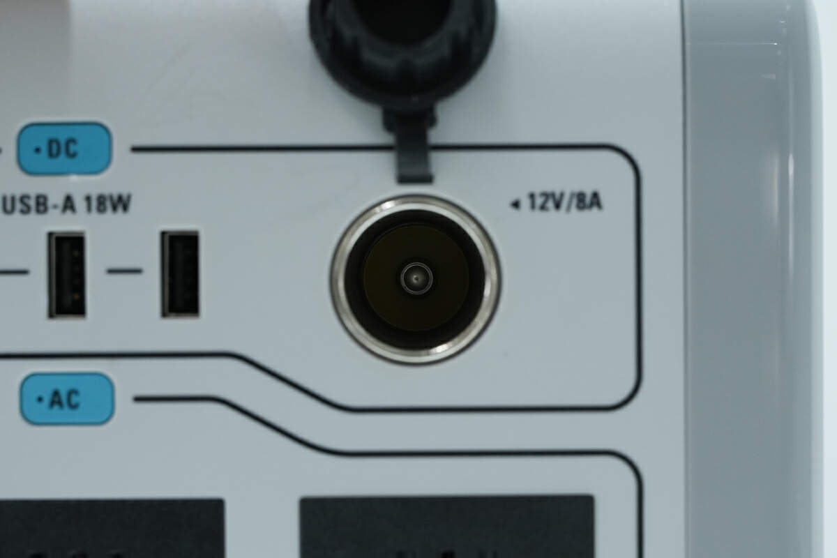
The car port has a rubber dust plug for protection. It can support an output of up to 12V 8A 96W, meeting the needs of most car electrical appliances.

The LED light is also equipped with an independent button, which can be turned on with one click. Press and hold the button for 2~3 seconds to enter SOS mode, and click again to turn off the light. The LED light can not only cope with day/night use scenarios, but can also provide a distress signal in emergency situations, which is very practical.
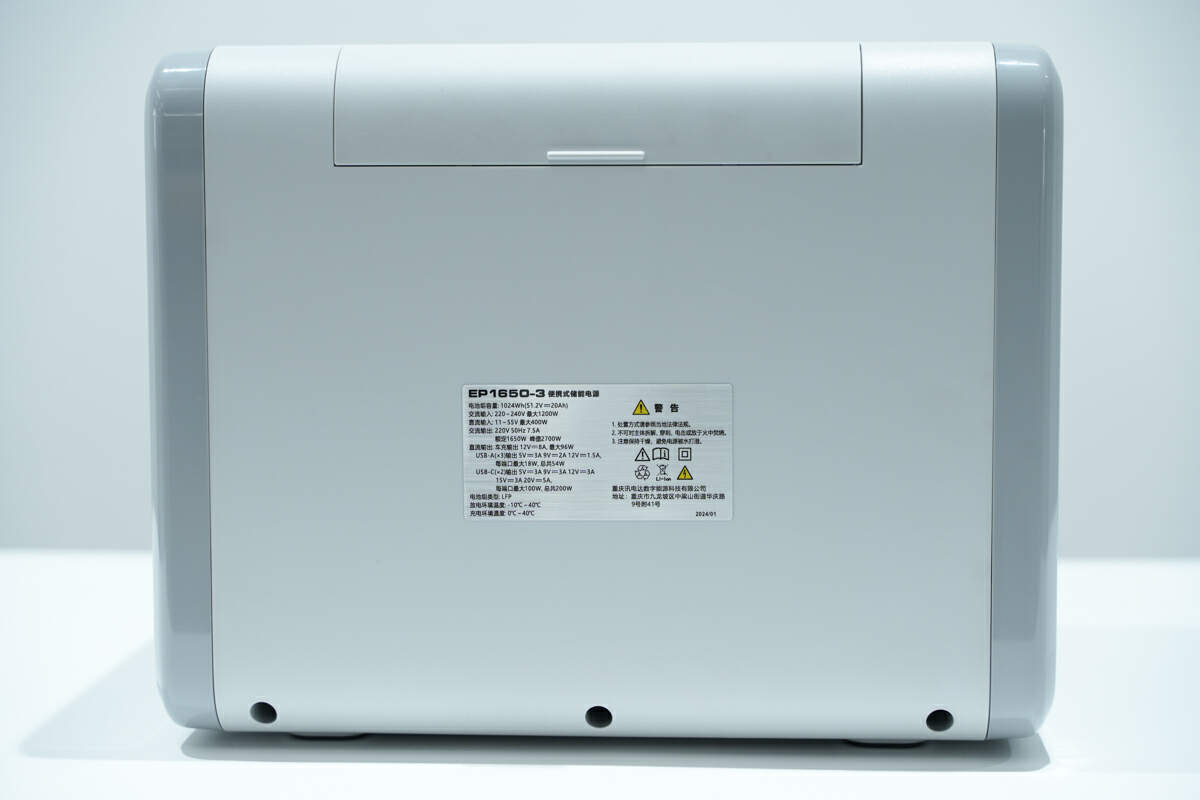
There is a hidden cover on the back. There are also some specs info pasted below the cover.
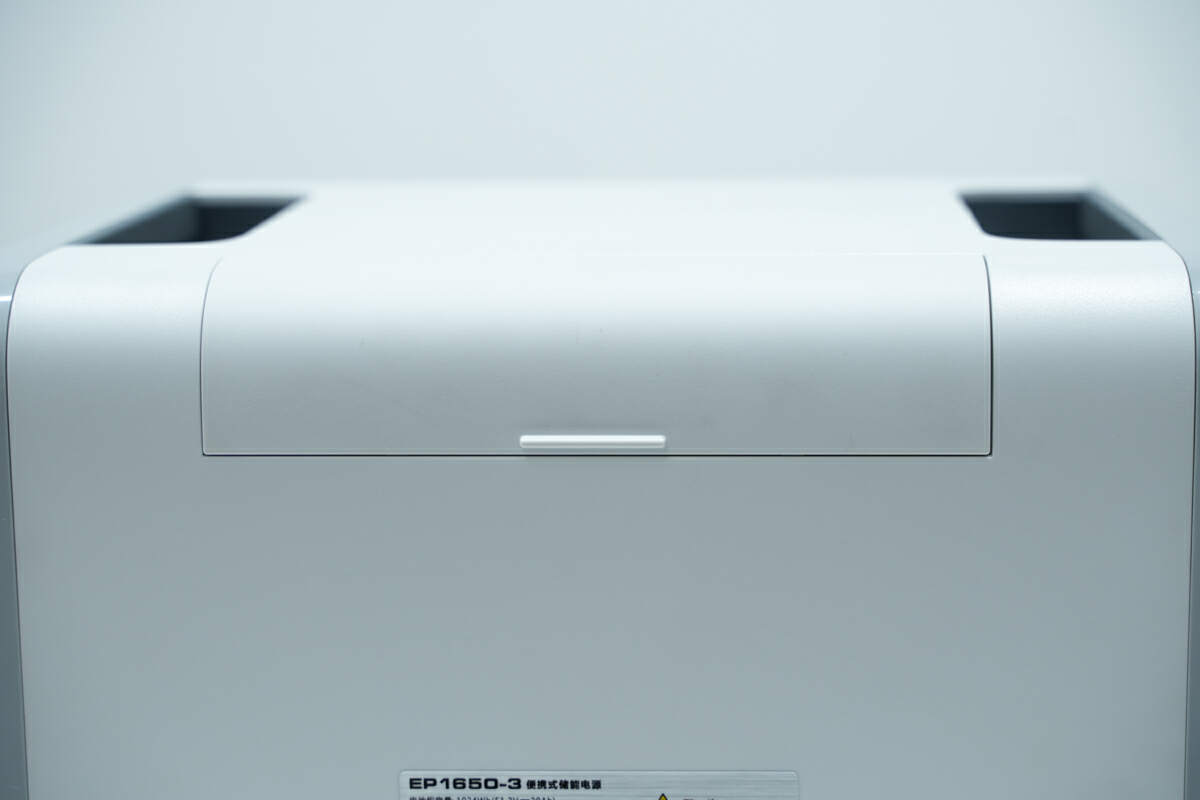
The tiny handle on the hidden cover is convenient for users to open.
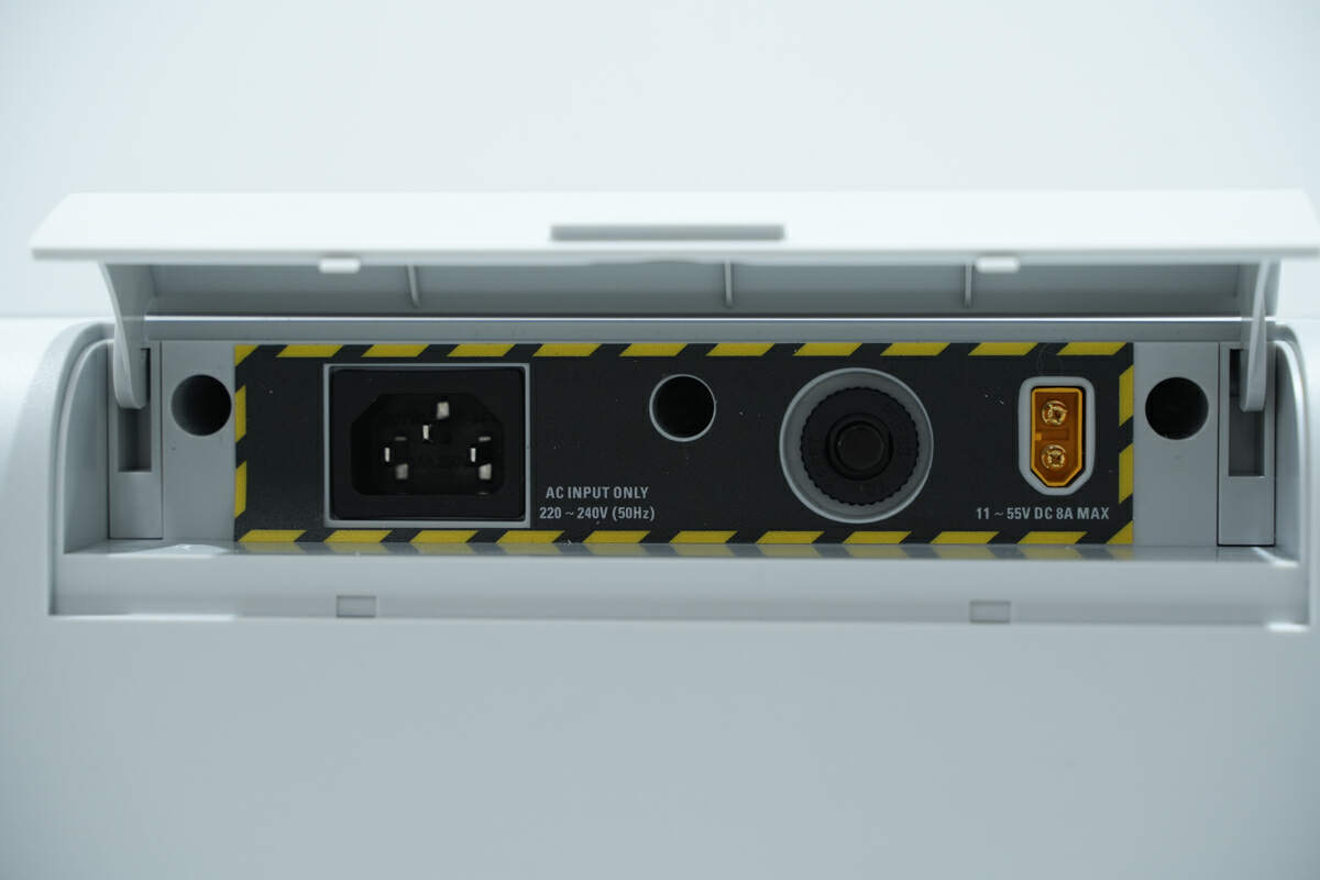
There is an AC input socket, an overload protector, and a DC input socket inside the hidden cover.
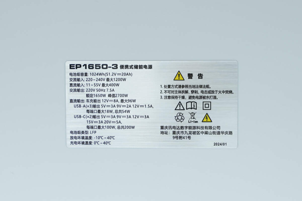
Model is EP1650-3. The battery capacity is 1024Wh. The AC input can support 220~240V 50Hz 10A 1200W. The DC input can support 11~55V 400W. The AC output can support 230V 50Hz 7.2A 1650W. The car port can support an output of 12V 8A 96W. Each USB-A port can output up to 12V 1.5A, and the total output power of three USB-A ports is 54W. Each USB-C port can output up to 20V 5A, and the total output power of two USB-C ports is 200W. The battery type is LFP.
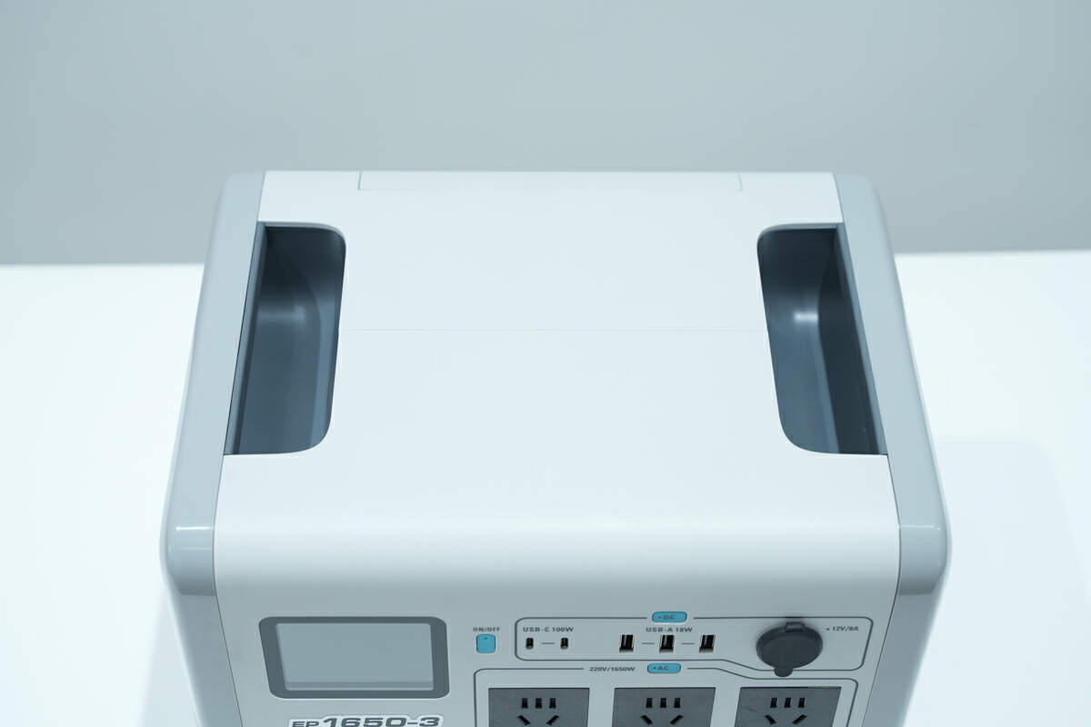
There are two hidden handles on both sides of the top, making it easier for users to carry it.
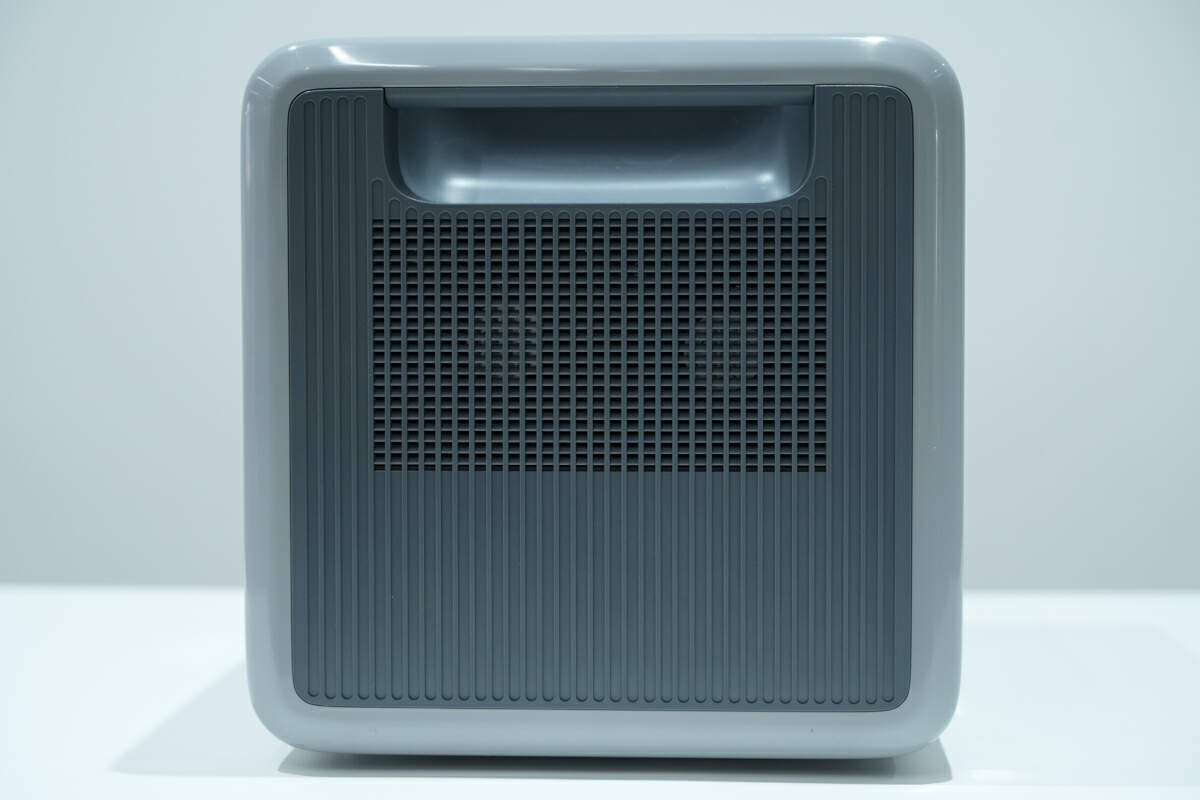
The two sides of it adopt a symmetrical design.
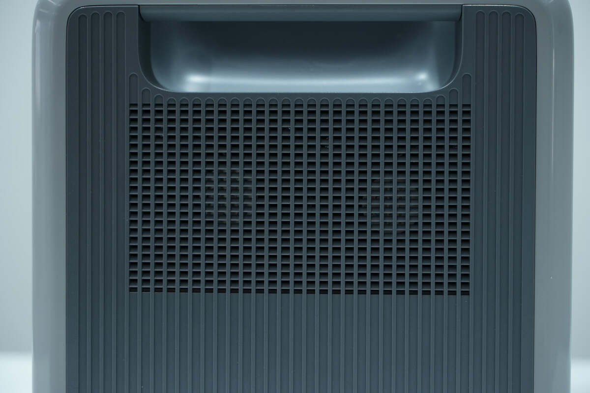
It is equipped with high-speed cooling fans on both sides. Paired with ventilation, it can protect safety and extend the lifespan.
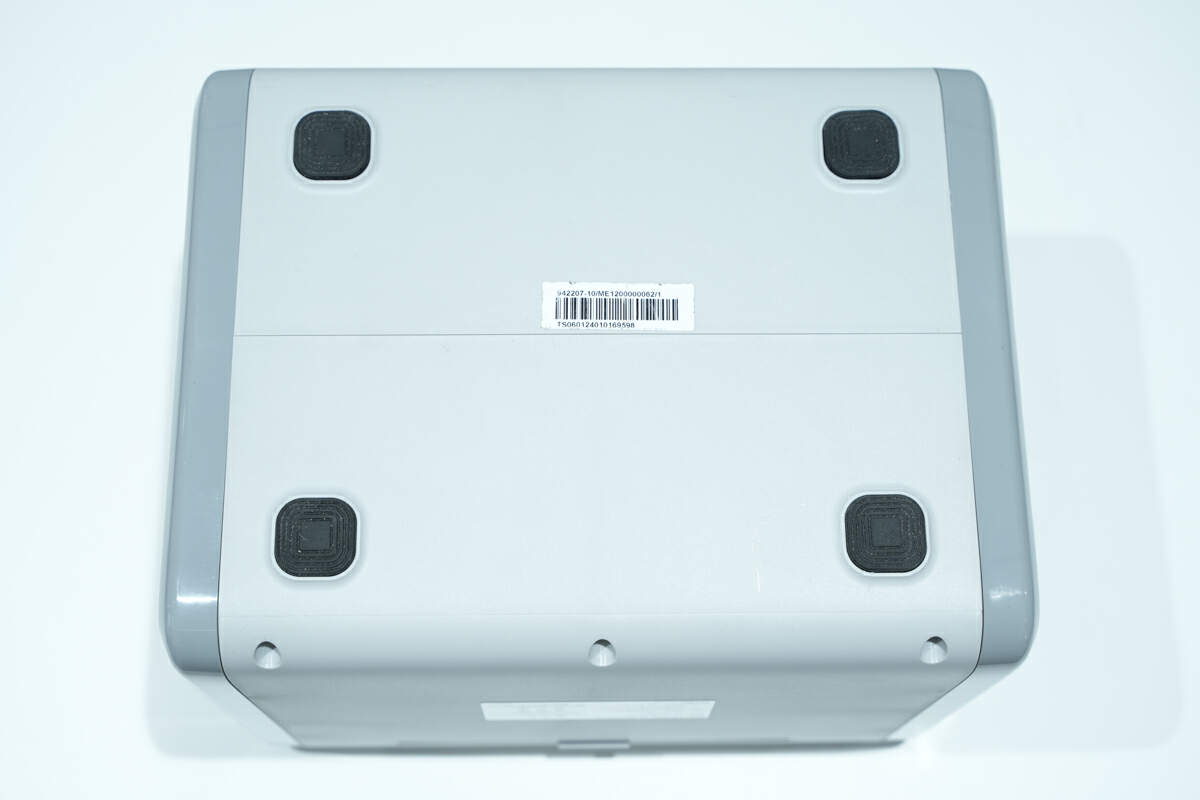
There are rubber pads at the four corners of the bottom to prevent sliding.

The length of it is about 34 cm (13.39 inches).

The width is about 26 cm (10.24 inches).

The height is about 26 cm (10.24 inches).

And the weight is about 13.7 kg (30.2 pounds).
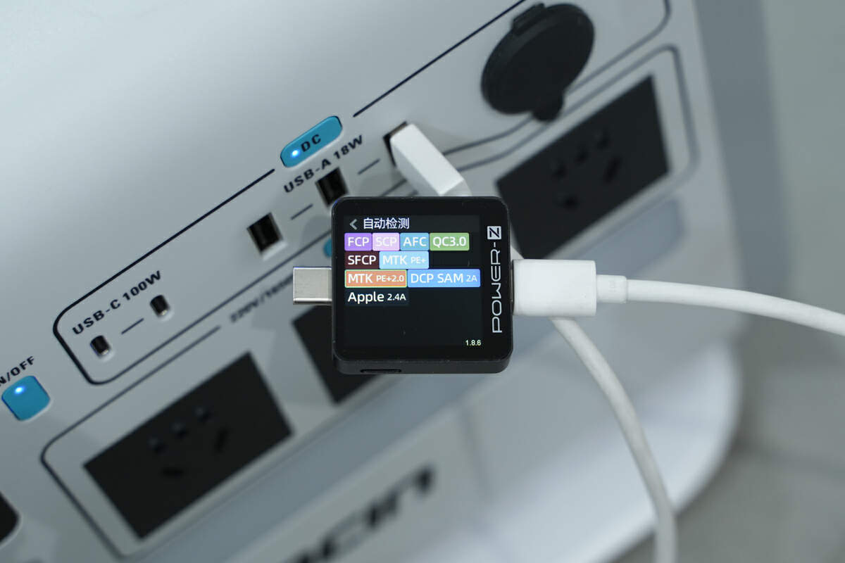
The ChargerLAB POWER-Z KM003C shows the USB-A port can support FCP, SCP, AFC, QC3.0, SFCP, PE2.0, DCP, SAM 2A, and Apple 2.4A charging protocols. The test results of the three USB-A ports are exactly the same.
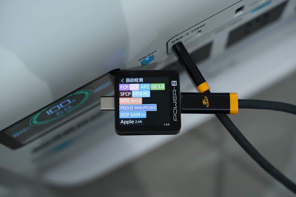
The ChargerLAB POWER-Z KM003C shows the first USB-C port can support FCP, SCP, AFC, QC3.0, QC5, SFCP, PE2.0, PD3.0, PPS, DCP, SAM 2A, and Apple 2.4A charging protocols.
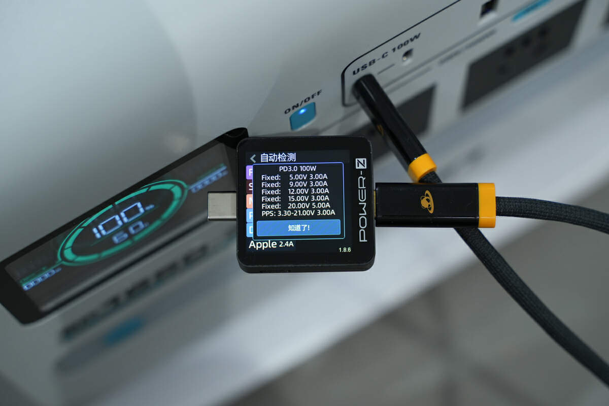
And it has five fixed PDOs of 5V3A, 9V3A, 12V3A, 15V3A, and 20V5A, and a set of PPS, which is 3.3-21V3A.
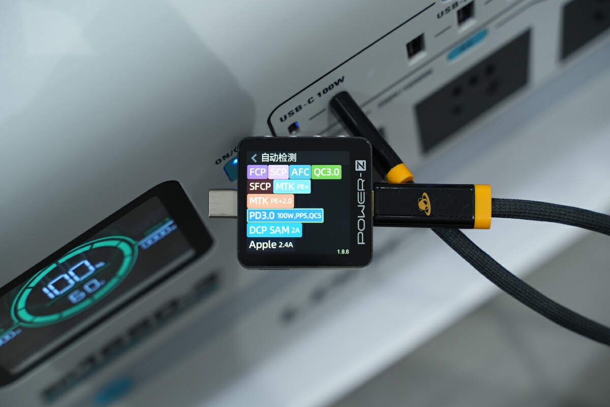
The second USB-C port supports the exact same protocols as the first USB-C port.
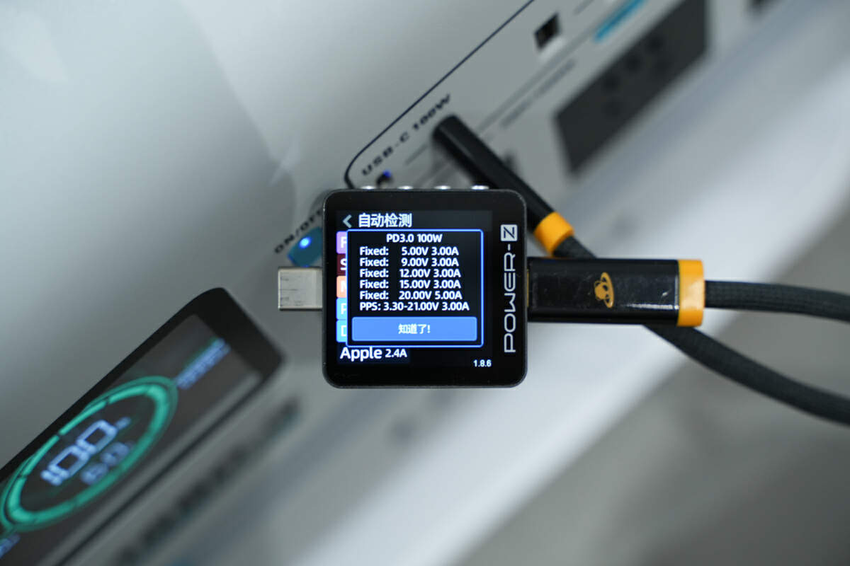
So as the PDOs.
The five USB ports have good compatibility and can meet the fast charging needs of laptops, tablets, and phones from Apple, Samsung, Xiaomi, Huawei, etc.
Teardown
After the product's appearance, let's start to take it apart.
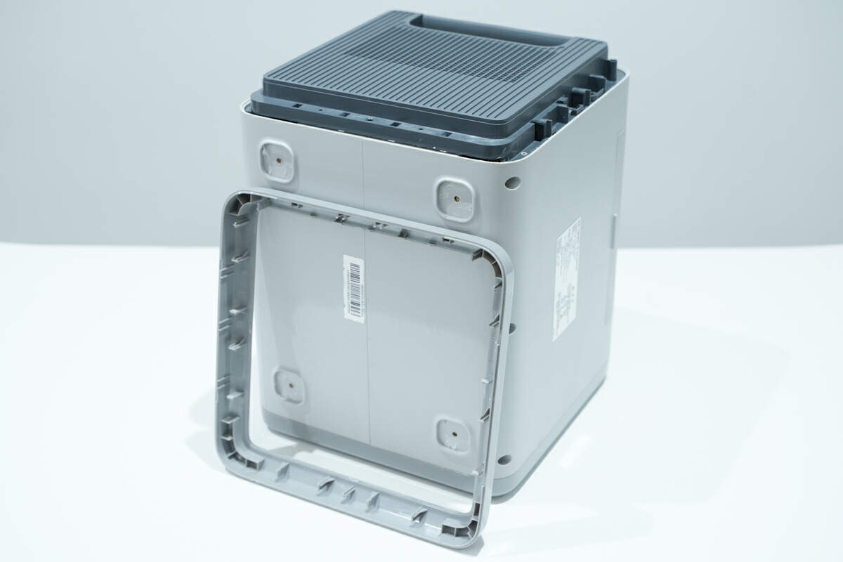
First, remove the side bracket fixed by clips.
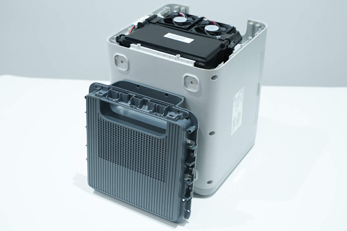
Unscrew the fixing screws and remove the side cover.
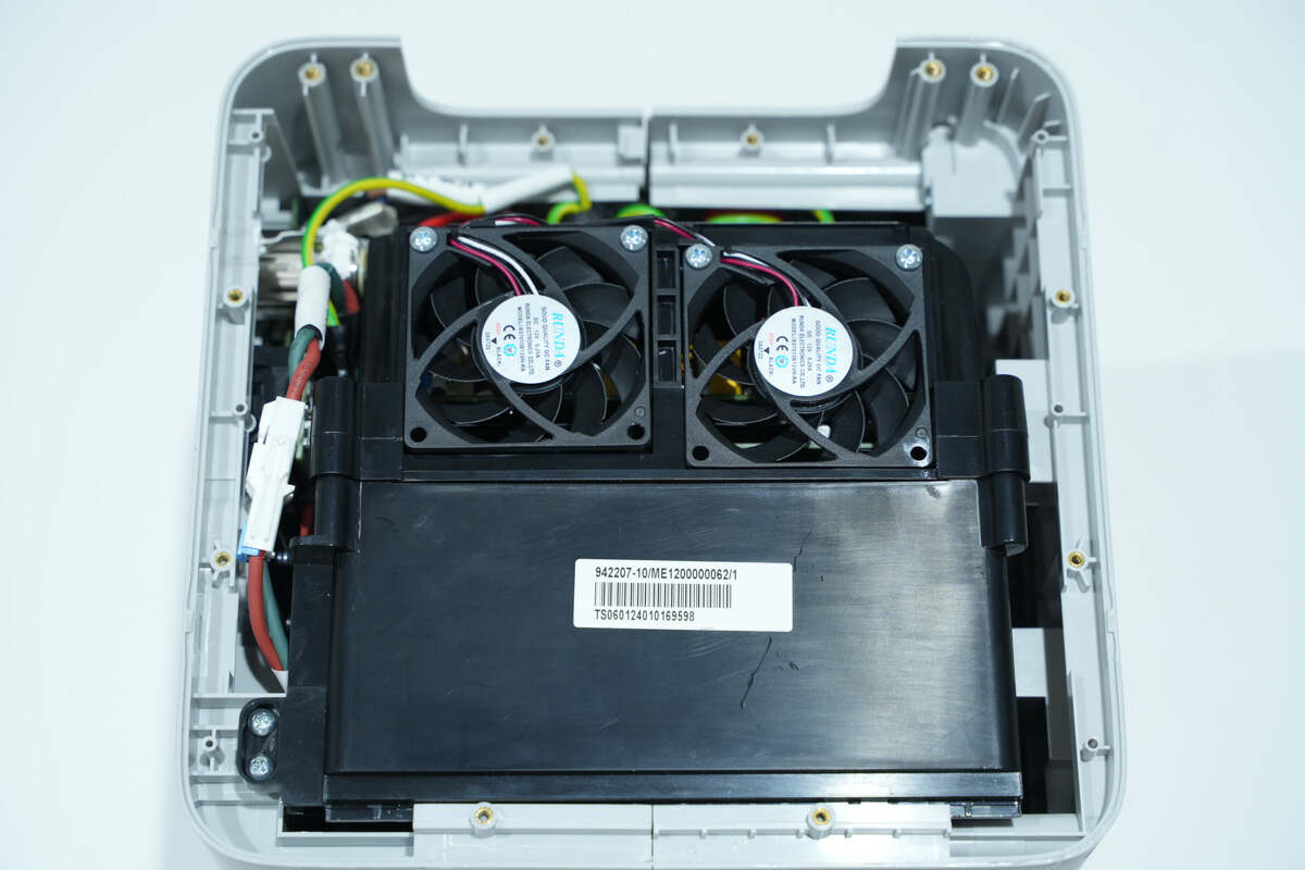
The battery pack and cooling fans are fixed inside the case.
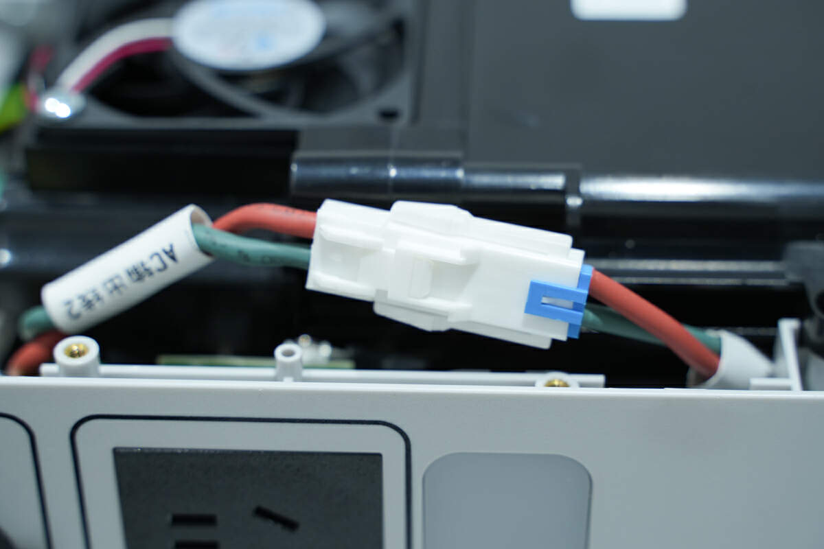
The AC output wires are connected via connectors.
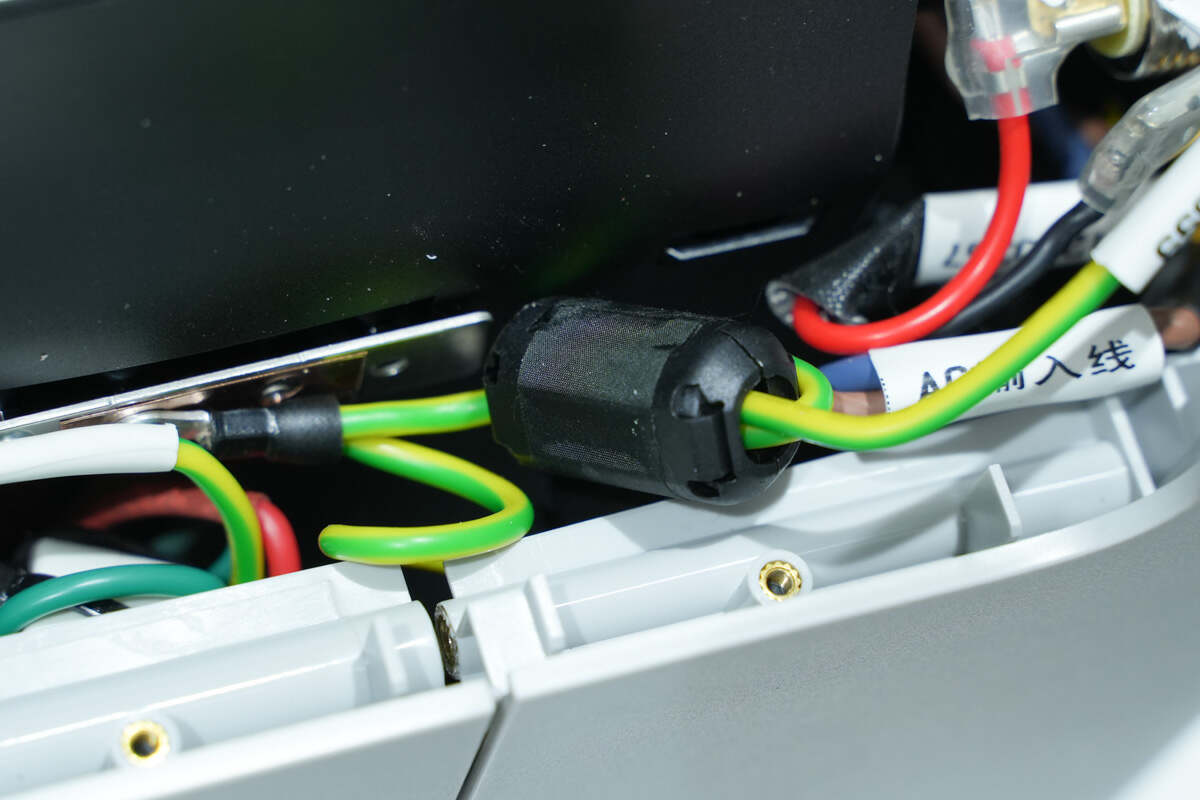
The ground wire has a magnetic ring for anti-interference.
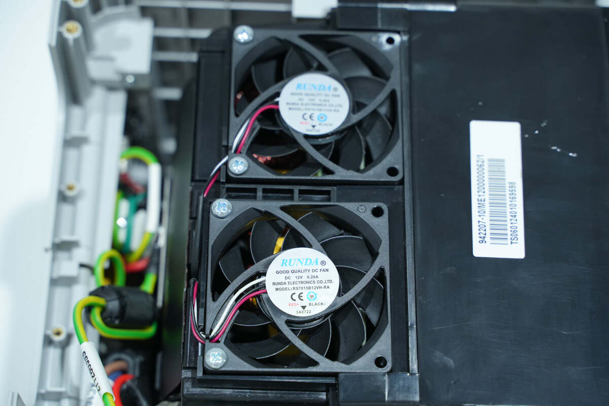
The two cooling fans are fixed with screws.
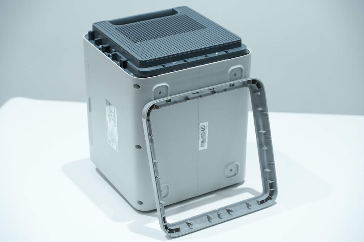
Remove the side bracket on the other side.
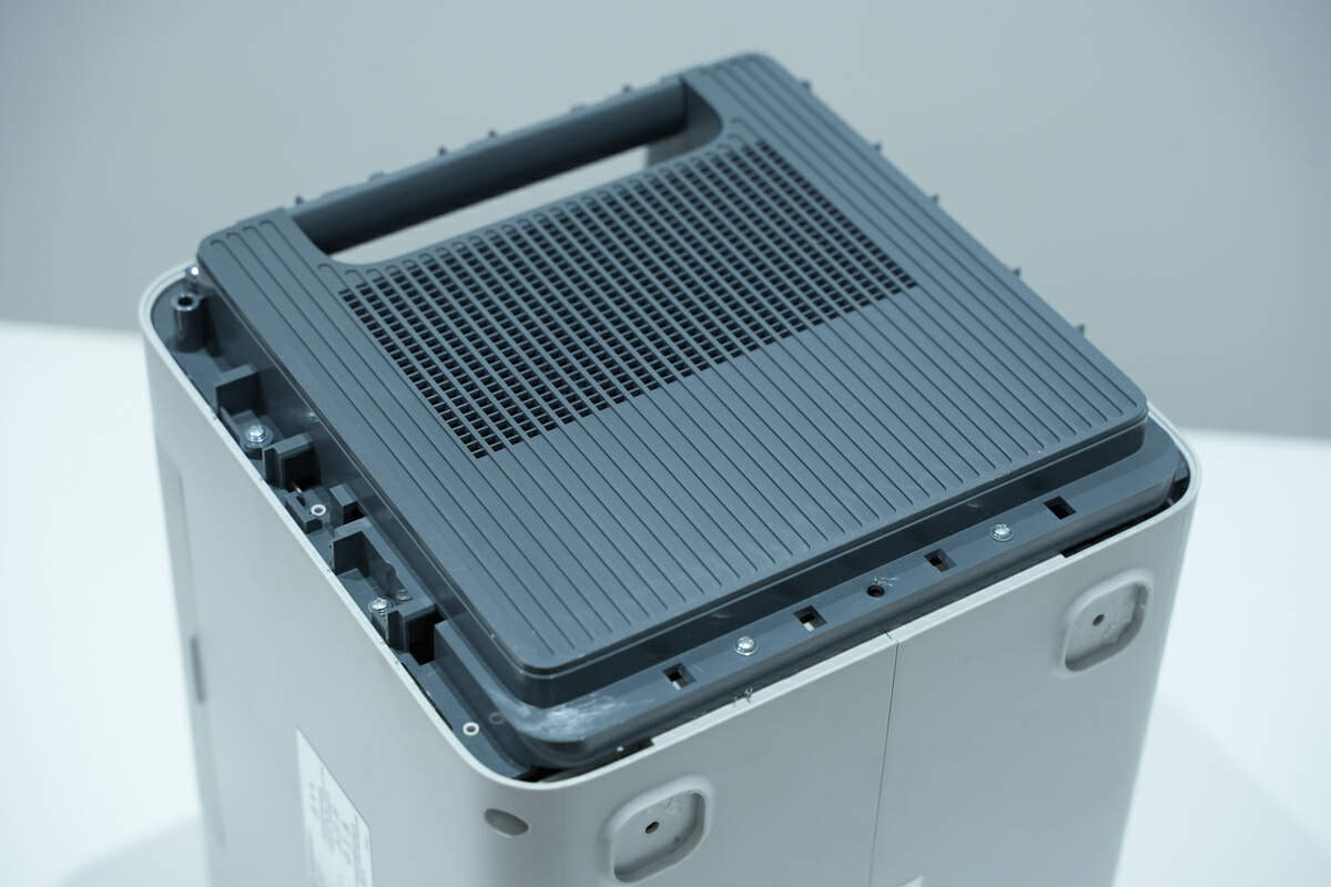
The side cover is fixed with screws.
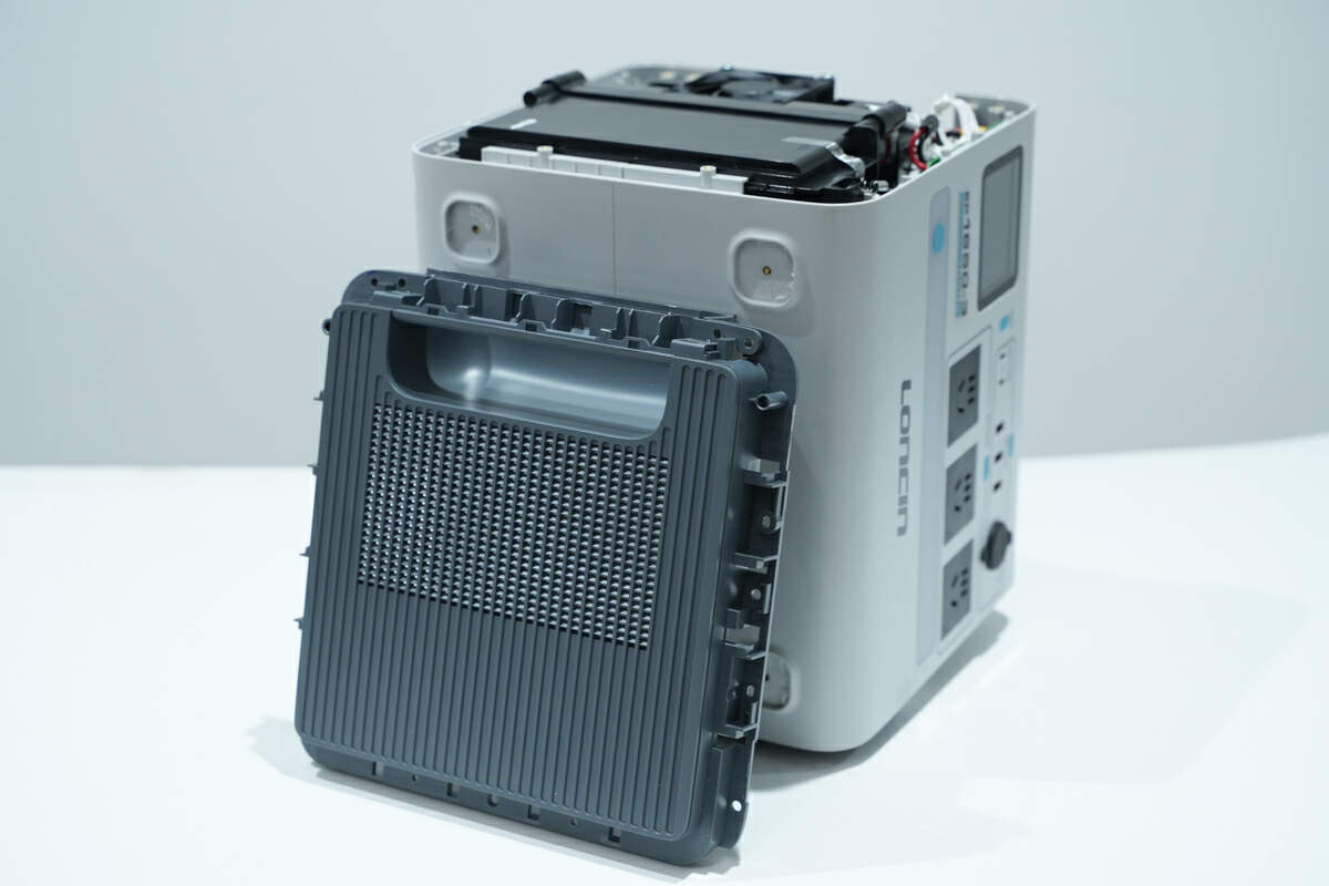
Unscrew the screws and remove the side cover.
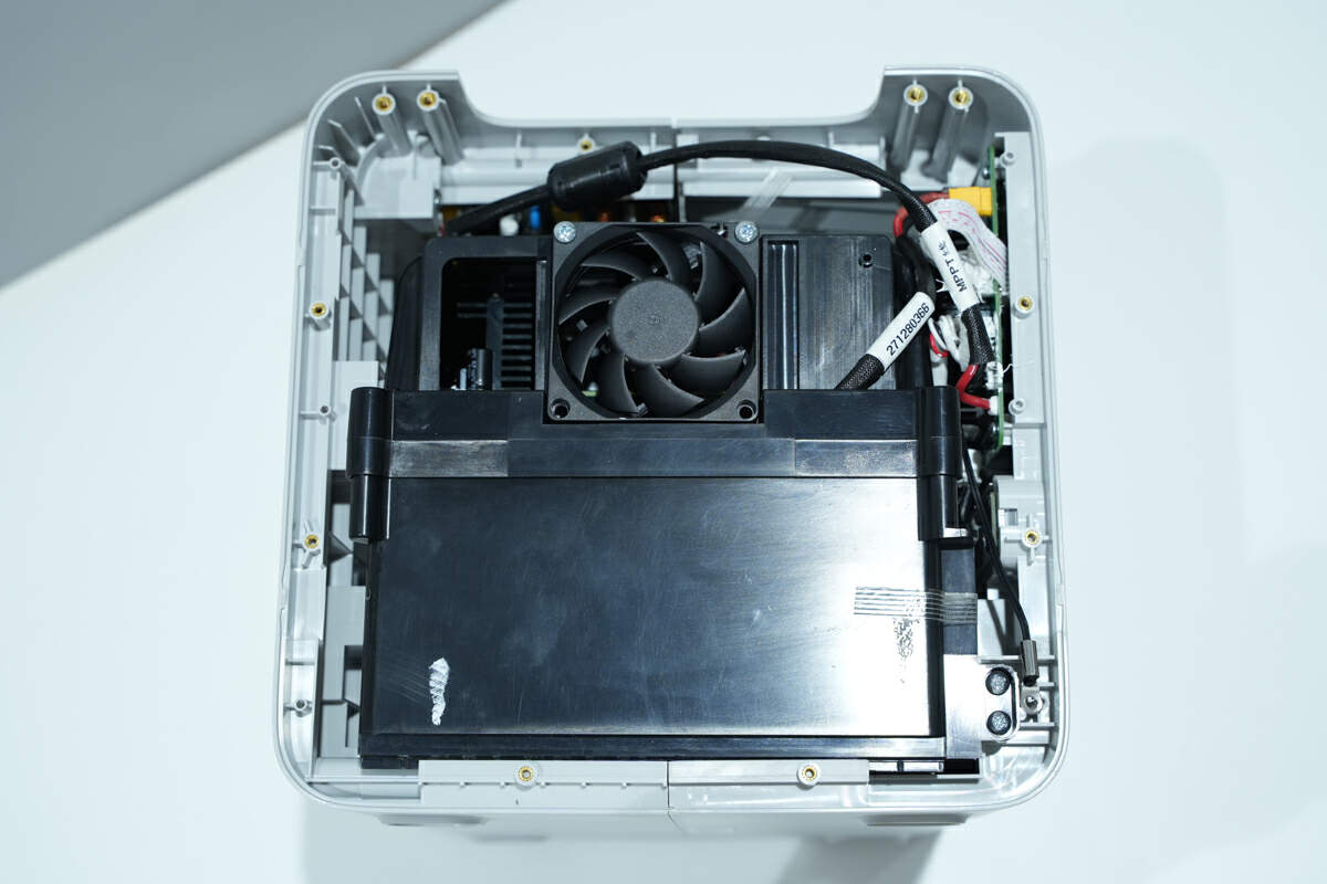
This side also has the battery pack and cooling fan.
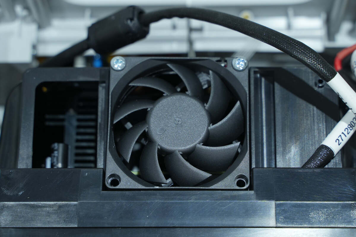
The cooling fan is fixed with screws.
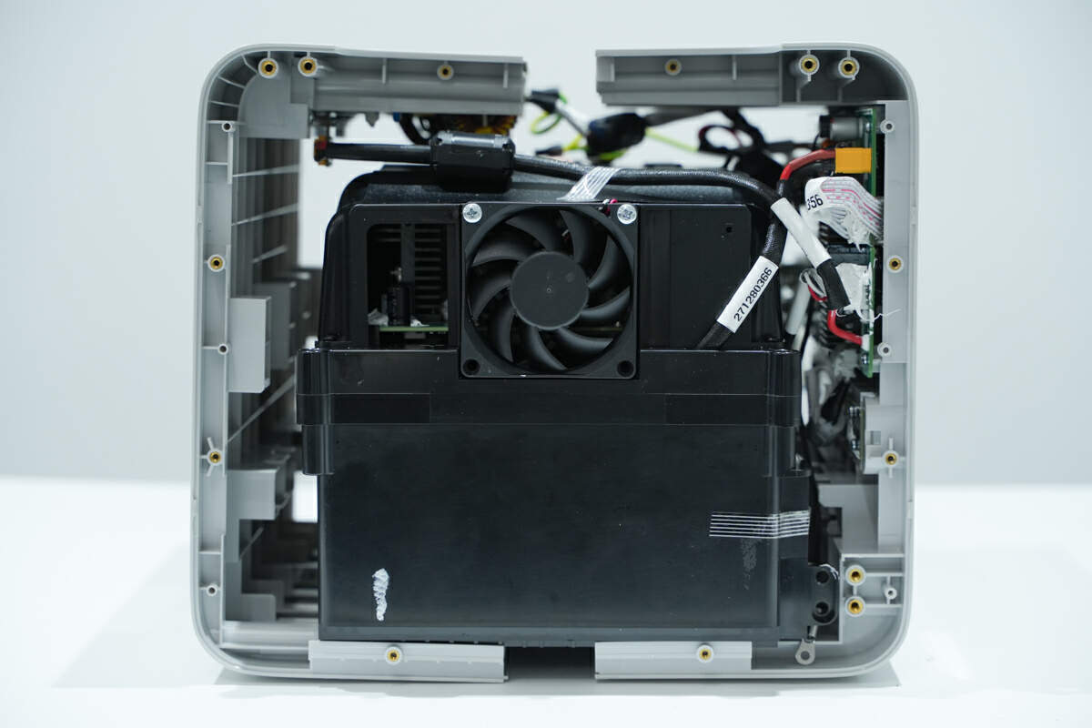
Unscrew the fixing screws on both sides of the case.
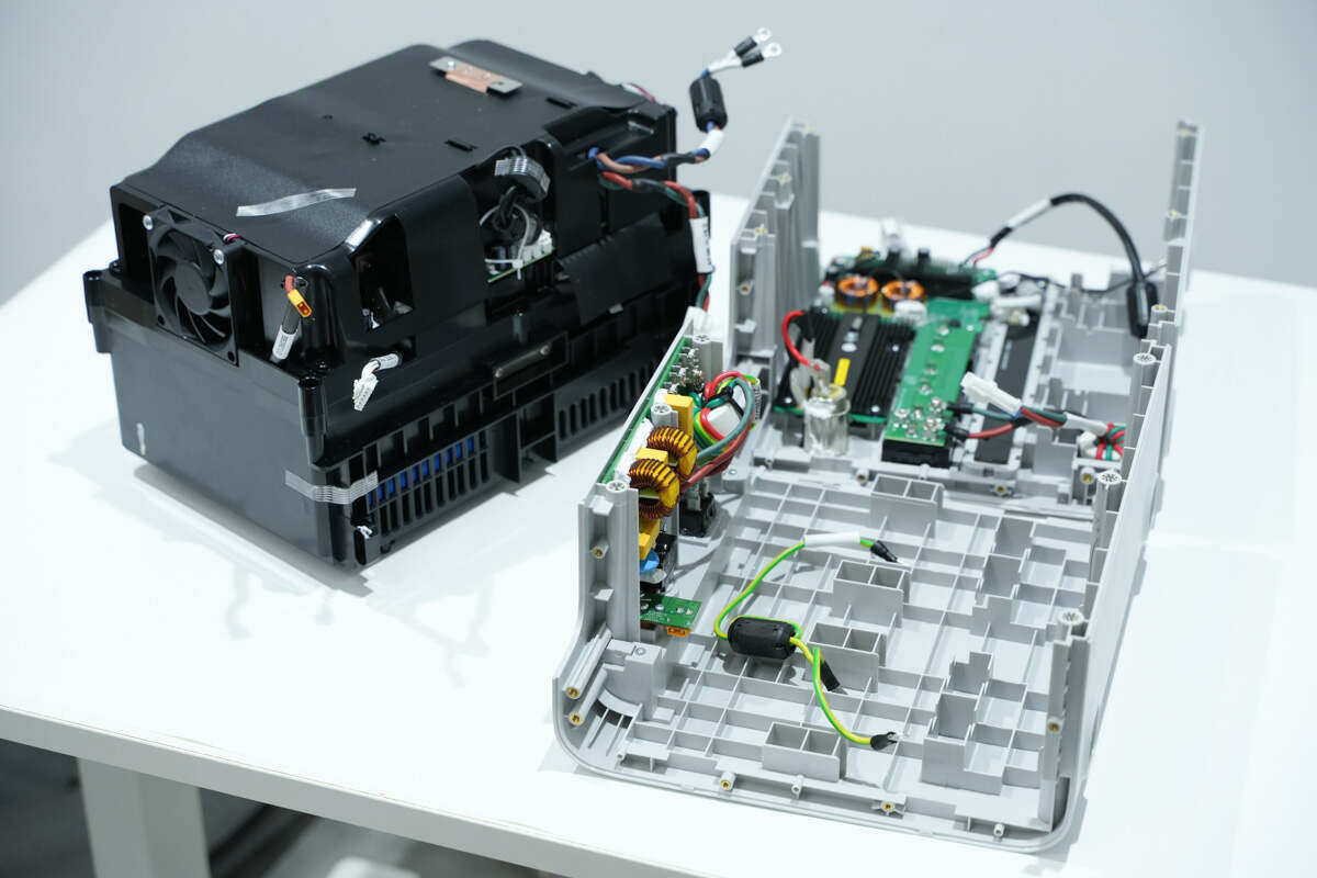
Take out the battery pack and bidirectional inverter module from the case.
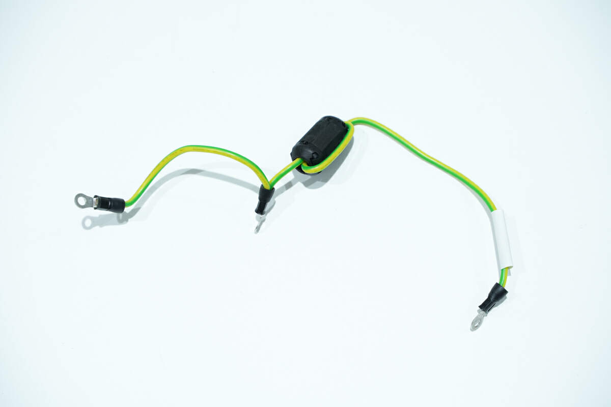
The connecting wire passes through the magnetic ring to suppress high-frequency interference.
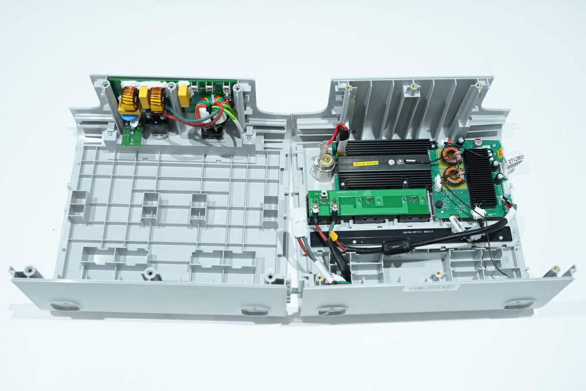
The input protection PCB and the fast charging output PCB are fixed on the case.
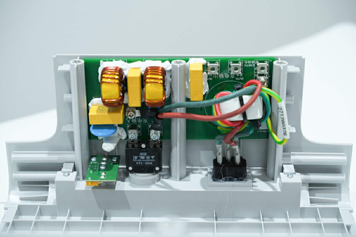
There are overload protector, varistor, safety X2 capacitor and common mode choke on the AC input protection PCB and EMI PCB.
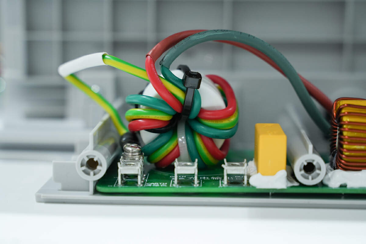
The filter inductor is fixed with zip ties.
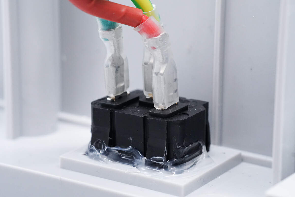
The input socket is connected via the connector.
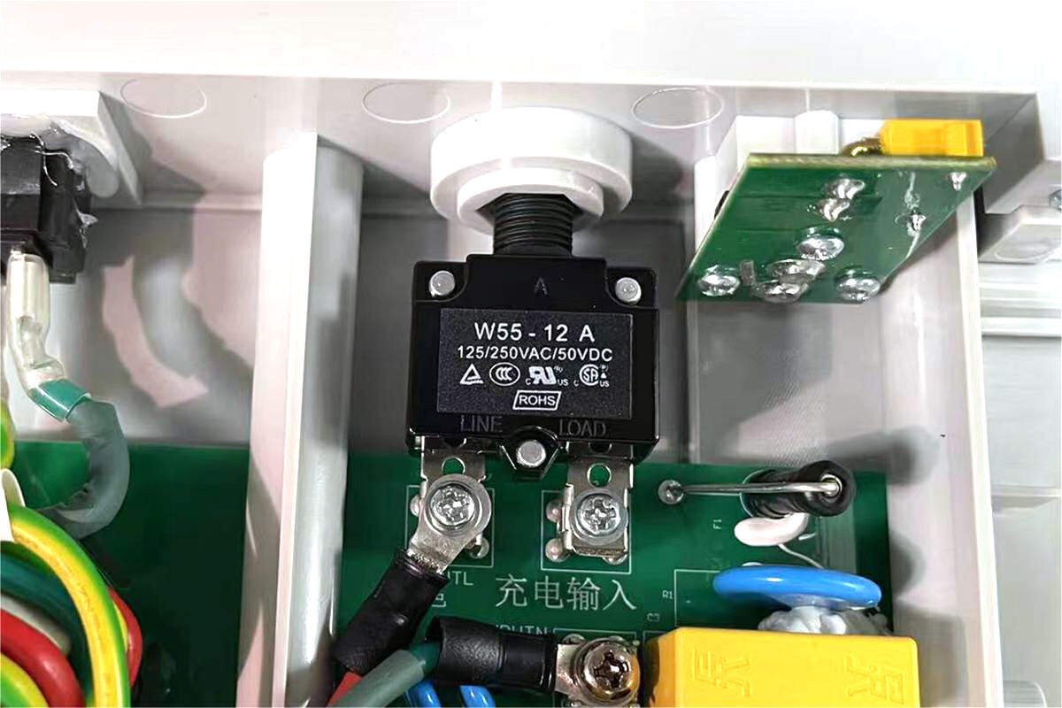
The overload protector is from Ygen. It is used for overload protection. Model is W55-12A.
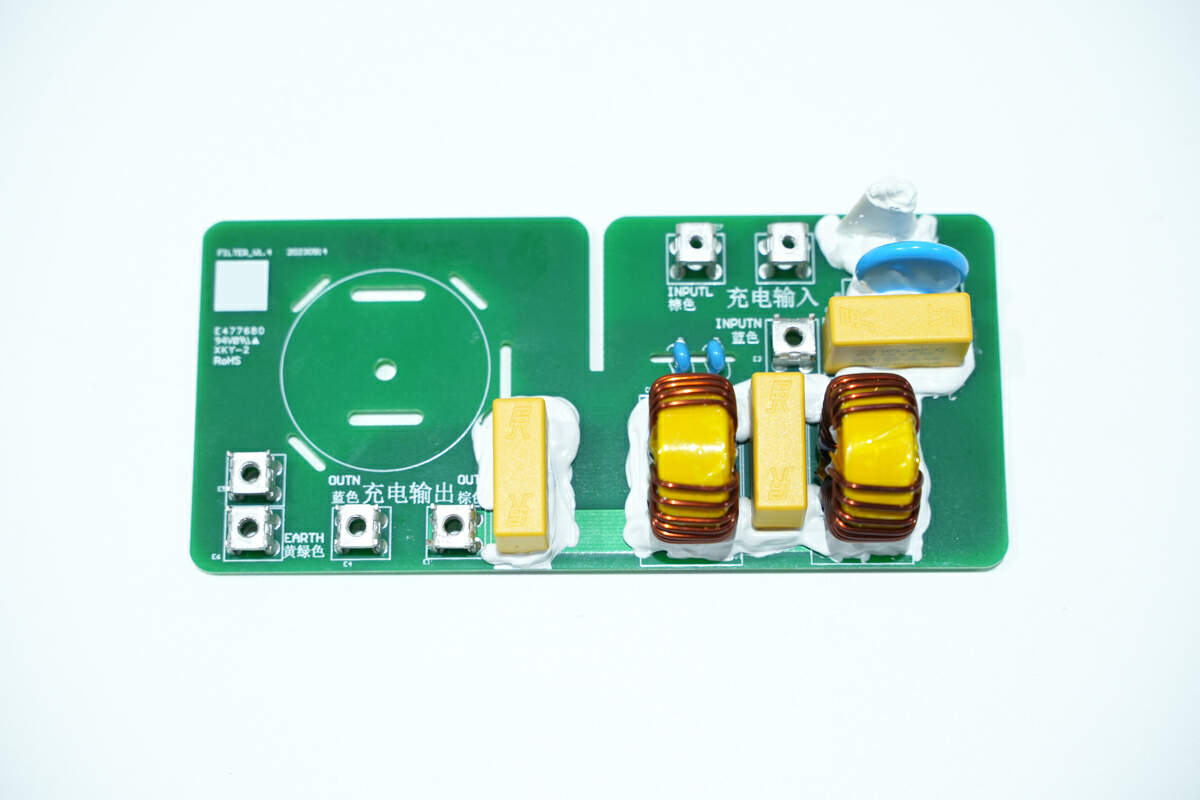
There are varistor, safety X2 capacitor, and common mode choke on the AC input protection PCB.
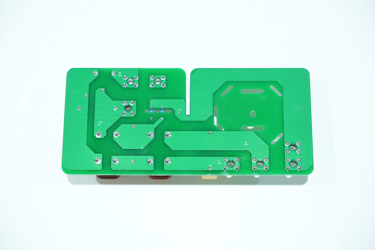
There are no components on the back.
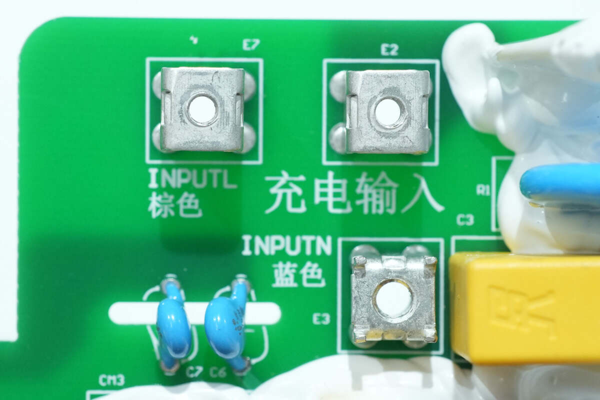
The AC input is connected via binding posts.
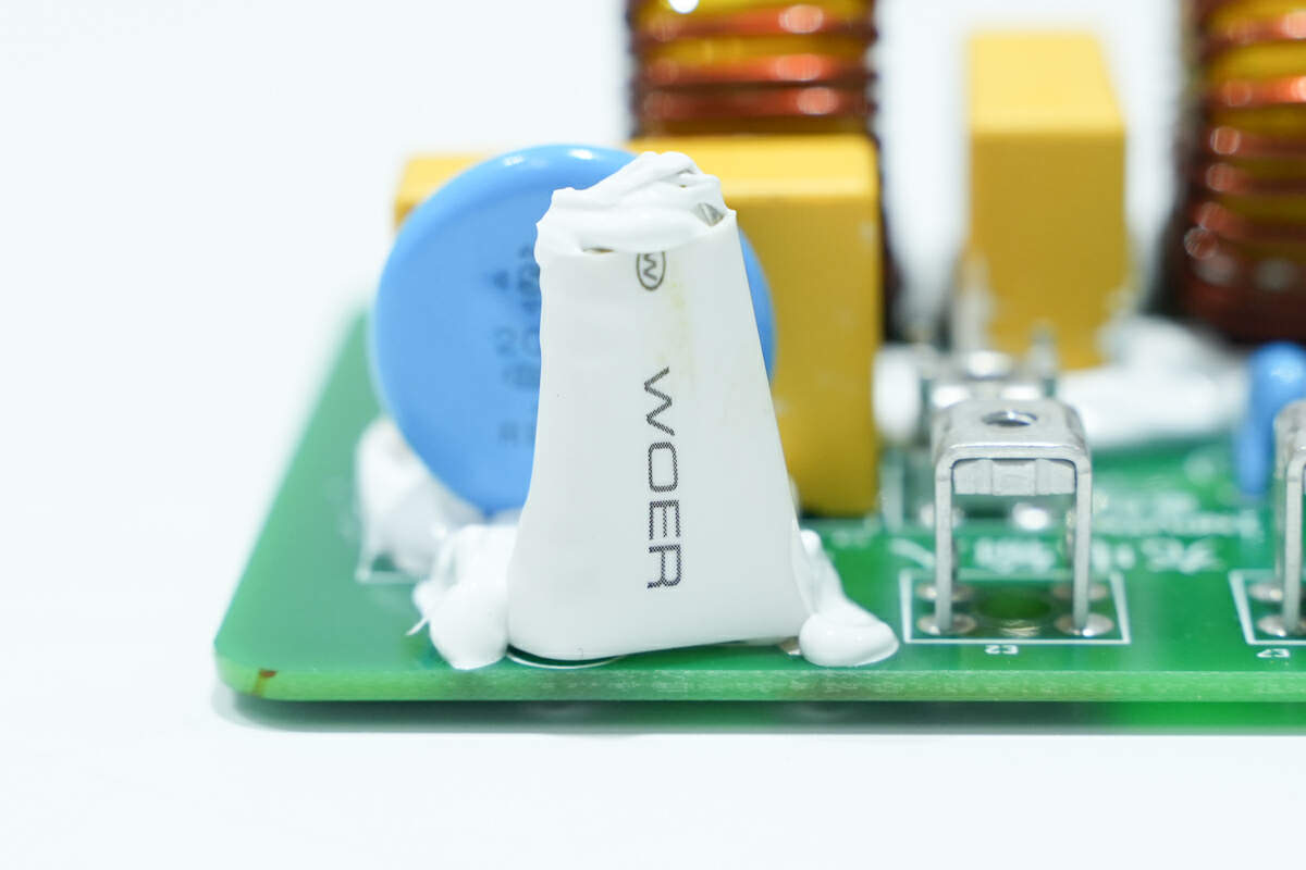
The input fuse is insulated by heat-shrinkable tubing.
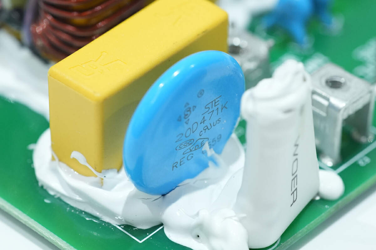
The varistor is from STE. Model is 20D471K.
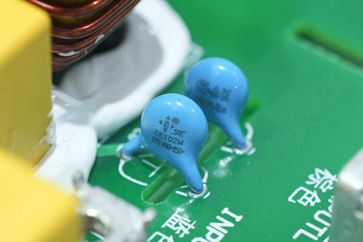
These two blue Y capacitors are also from STE.
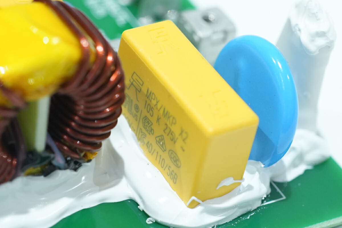
The safety X2 capacitor is from SINCERITY. 1μF.
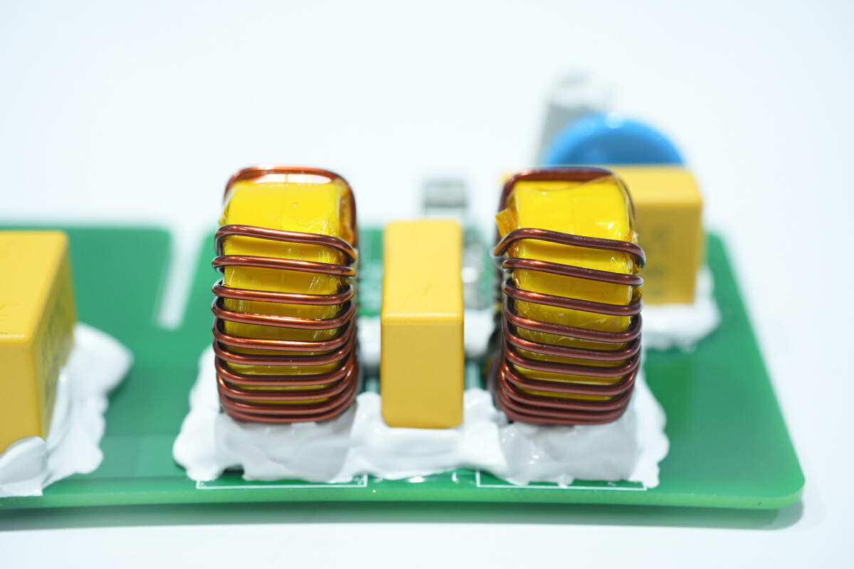
These two common mode chokes and safety X2 capacitors are fixed with glue. The common mode chokes are wounded with magnetic rings.
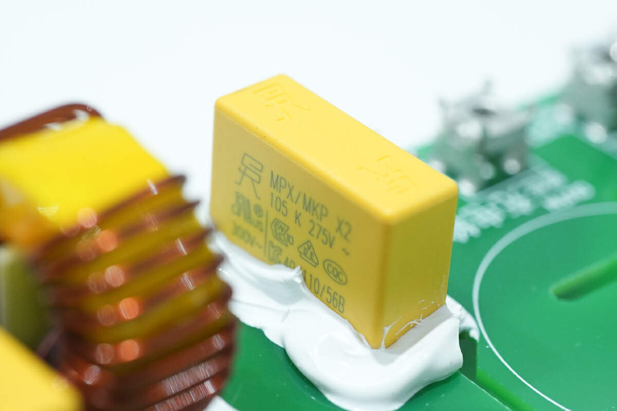
The other safety X2 capacitor is also from SINCERITY. 1μF.
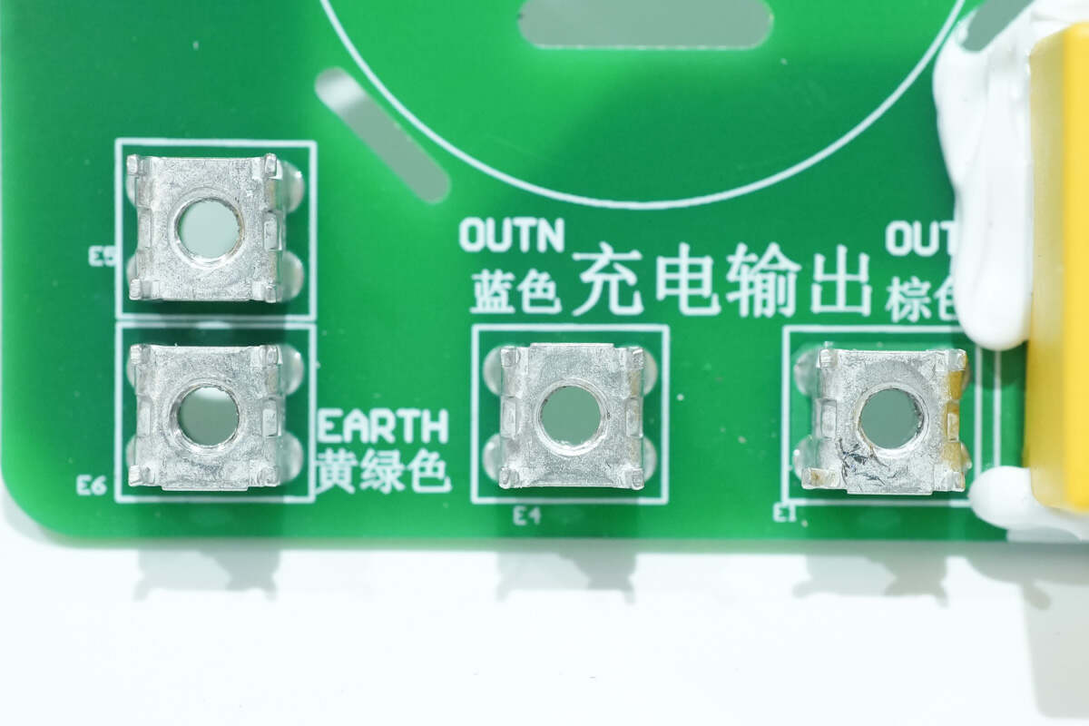
There are binding posts for output.
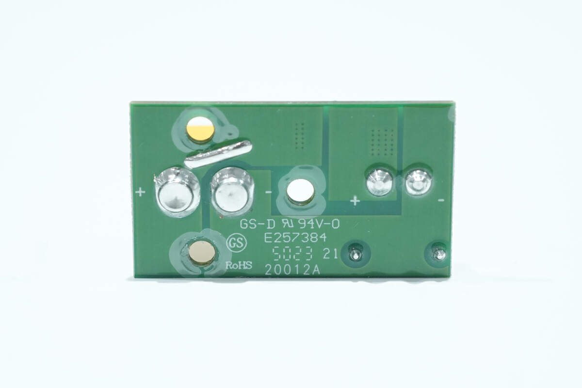
There are no components on the back.
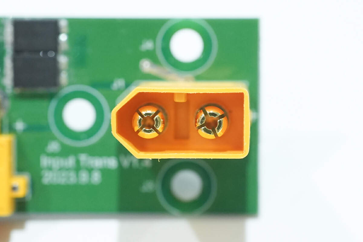
Here is the XT60 connector.
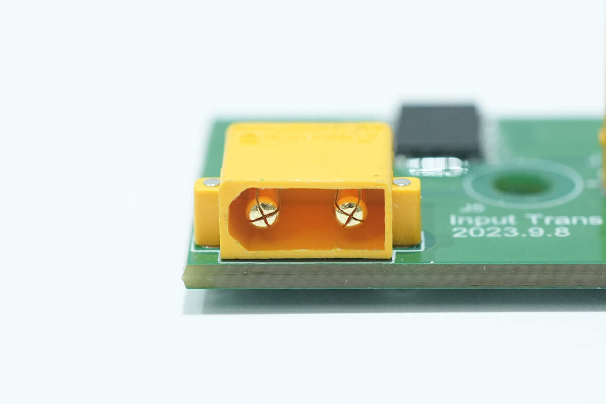
Here is the XT30 connector.
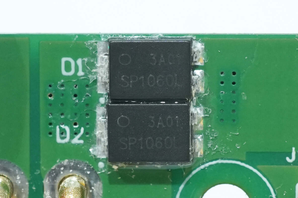
These two Schottky diodes are connected in parallel and adopt TO-277 package. They are used to block DC input current flow when Reverse Biased. Model is SP1060L. 10A 60V.
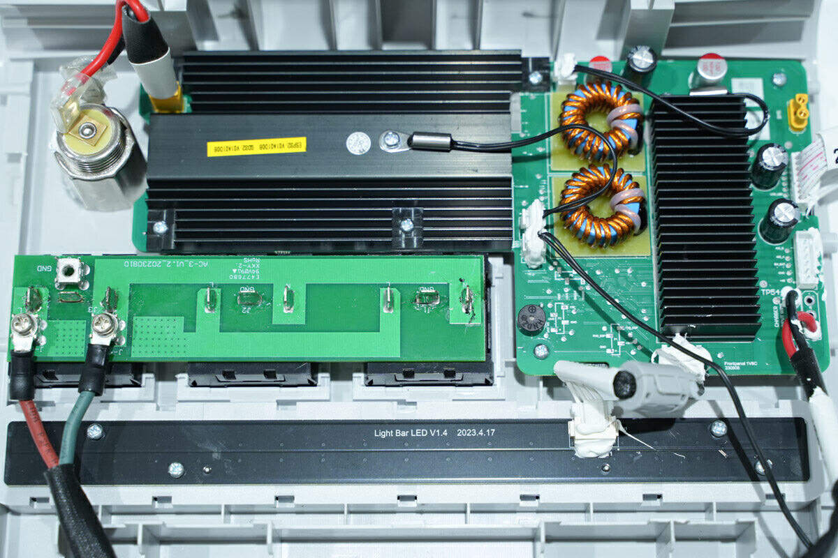
There is a light bar, and PCBs of AC outlets and fast-charging on the other side of the case. The light bar is fixed with screws.
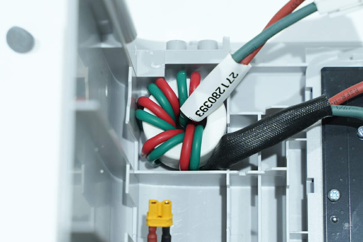
The magnetic ring inside the case is used to resist interference.
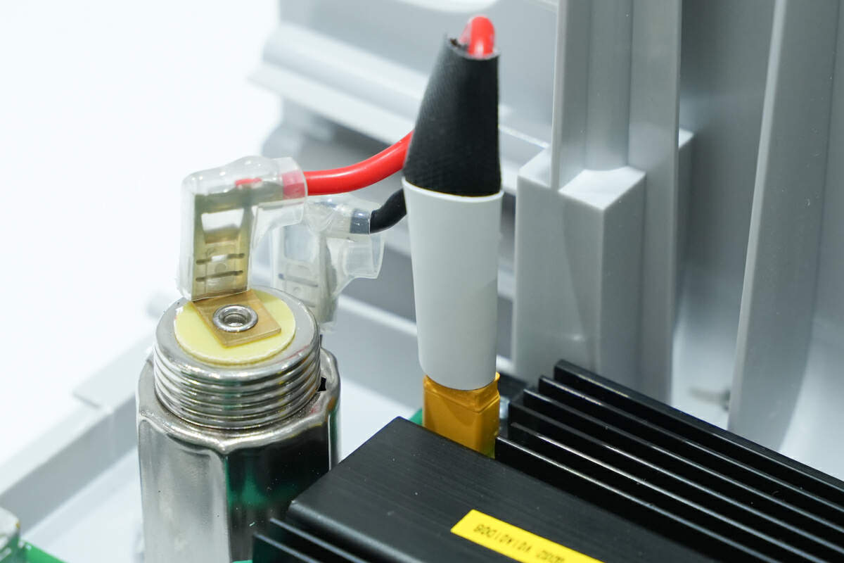
The socket of the car charger is connected by an XT30 connector.
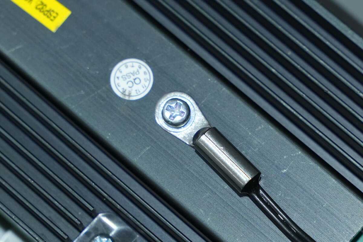
The thermistor is fixed on the heat sink.
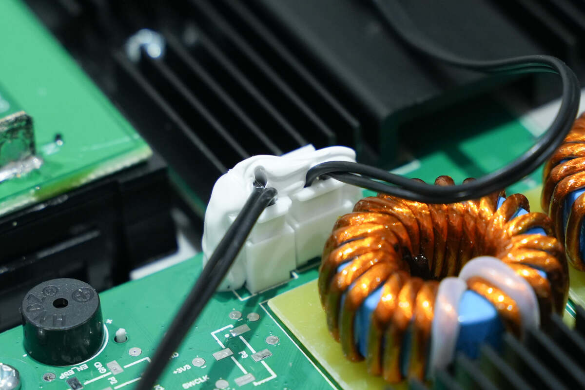
Here is the connector for the thermistor, and the wires are fixed with glue.
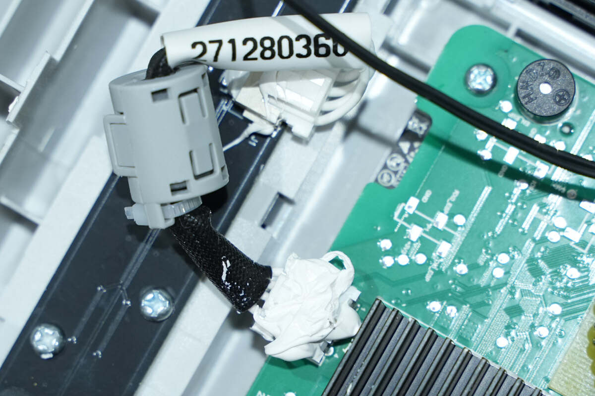
The connecting wires are protected by the magnetic ring to suppress interference.
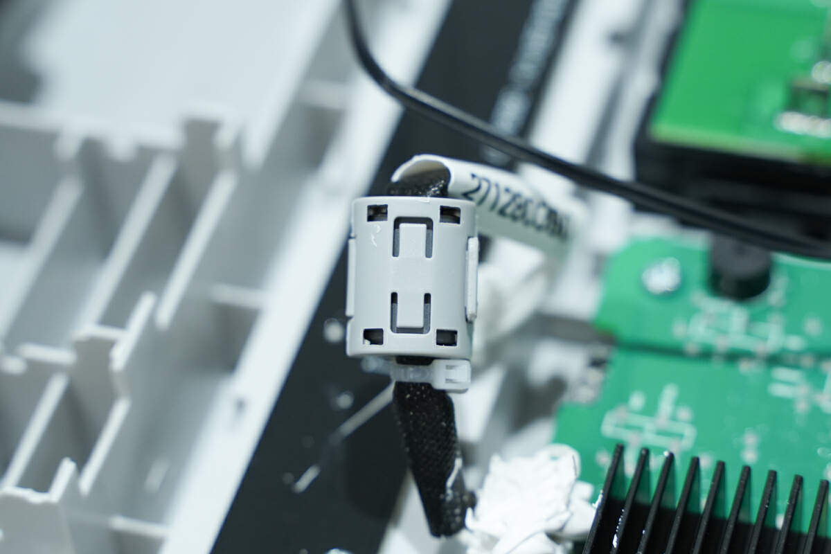
The wires connected to the light bar also use the magnetic ring to suppress high-frequency interference.
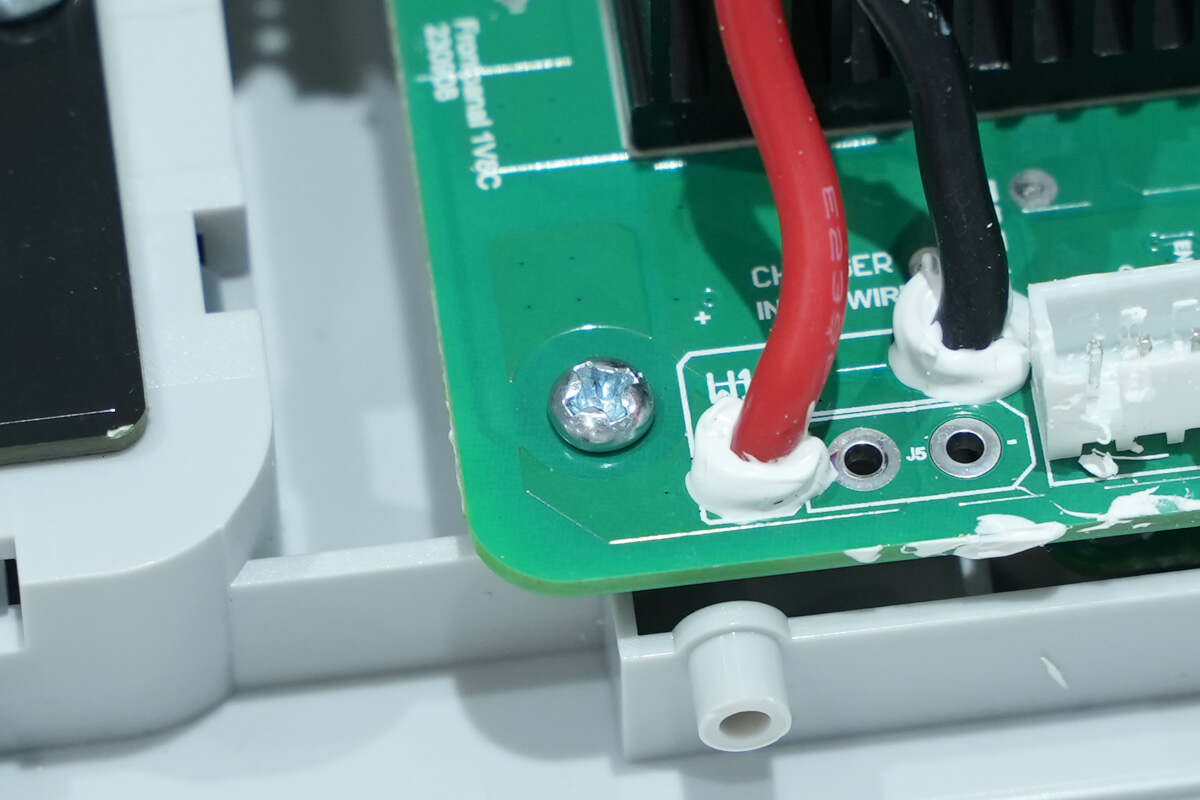
The PCB of fast-charging is fixed by screws.
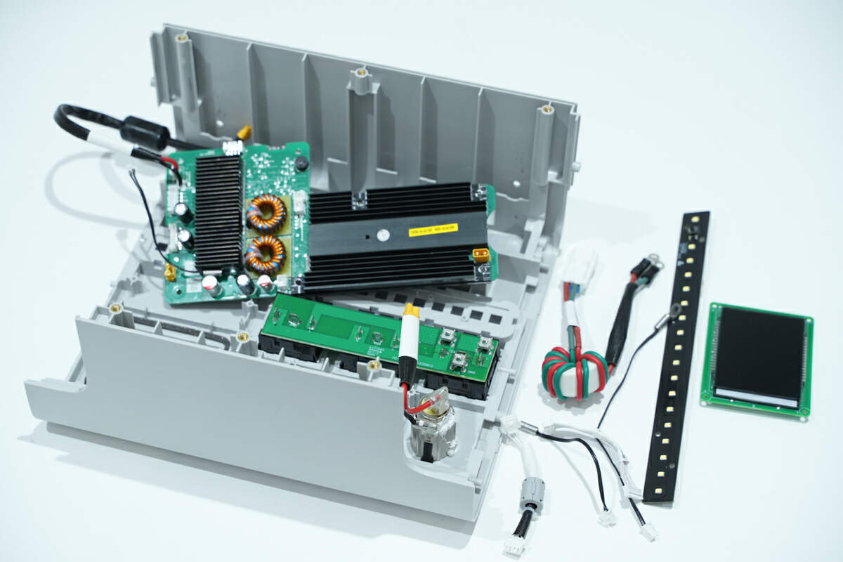
Unscrew the fixing screws and remove the LCD, fast-charging PCB, and light bar.
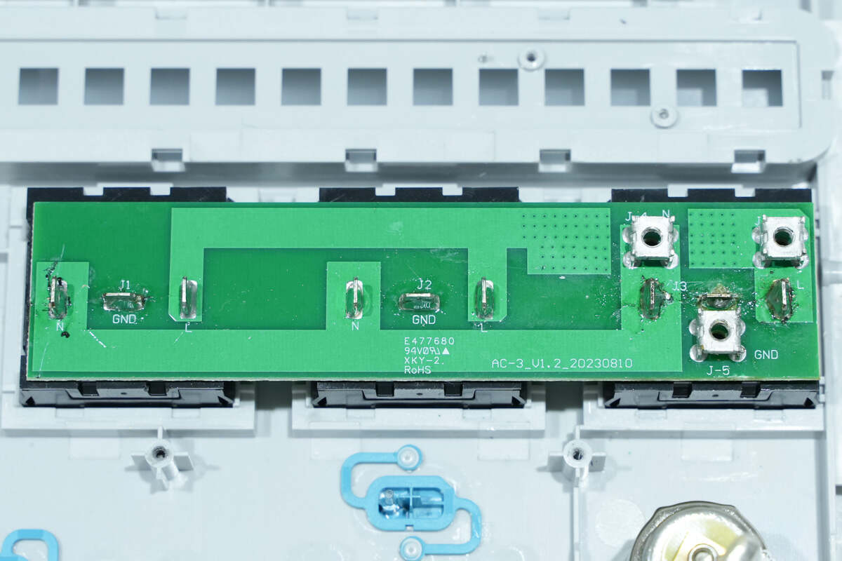
There are binding posts on the right of the PCB of AC outlets.
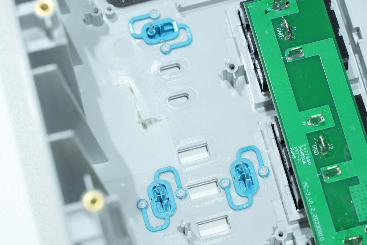
There are openings of the USB ports and blue buttons.
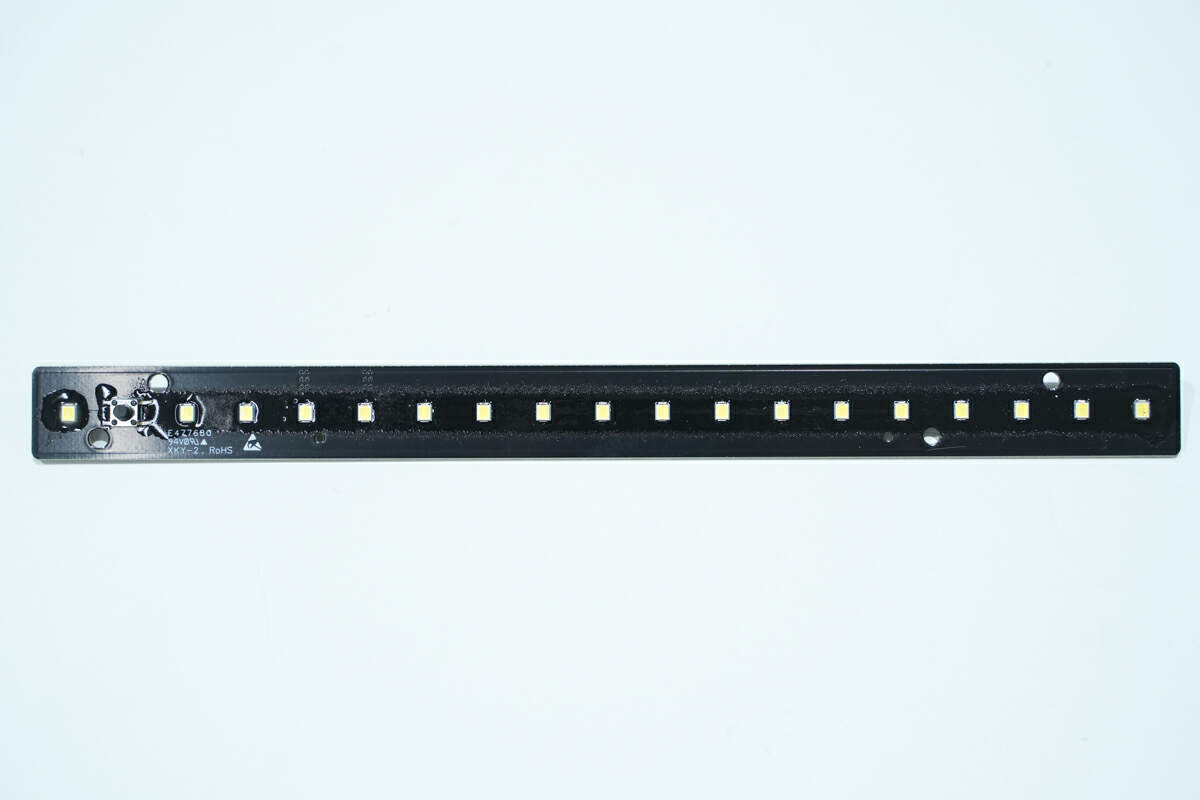
There are 18 LED lamp beads on the light bar.
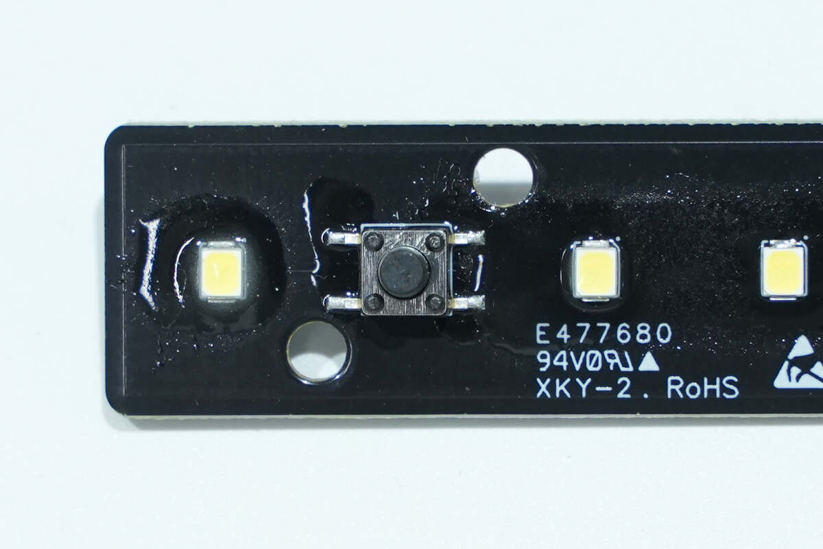
The SMD switch button is used to control the LED light.
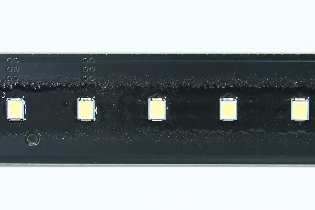
Here are the LED lamp beads.
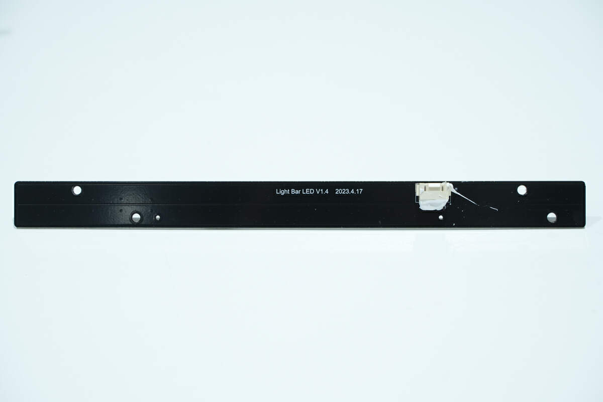
The socket is soldered on the back of the light bar.
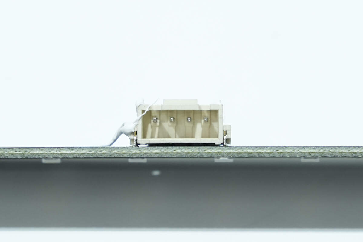
Here is the socket of the LED light bar.
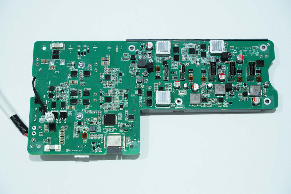
The MCU, wireless communication module, buck inductor, and USB sockets are on the front of the fast-charging PCB.
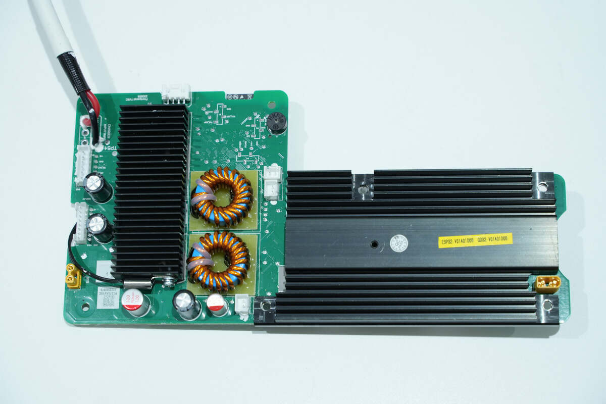
There are two heat sinks, inductors and the filter capacitor on the back of the fast-charging PCB. Both heat sinks are equipped with thermistors to detect temperature rise.
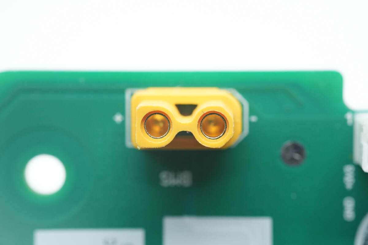
Here is the XT30 connector for the battery pack.
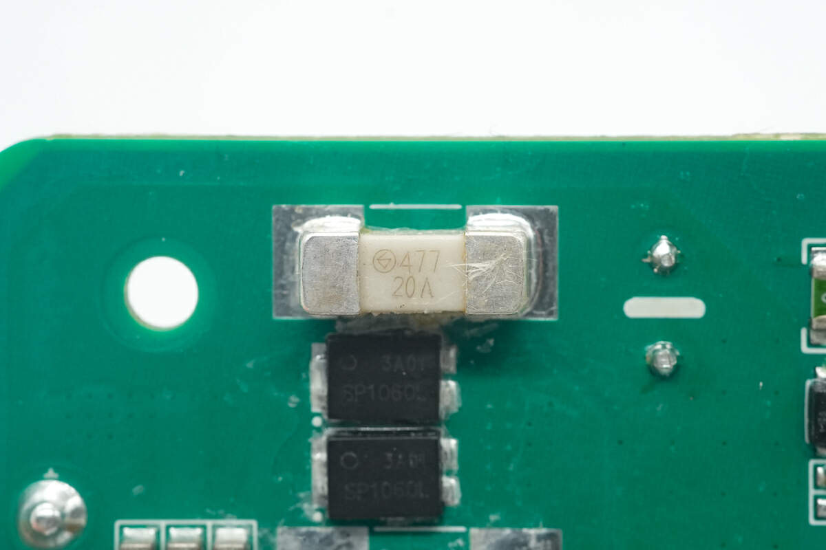
The fuse marked with 477 is from Betterfuse. 20A.
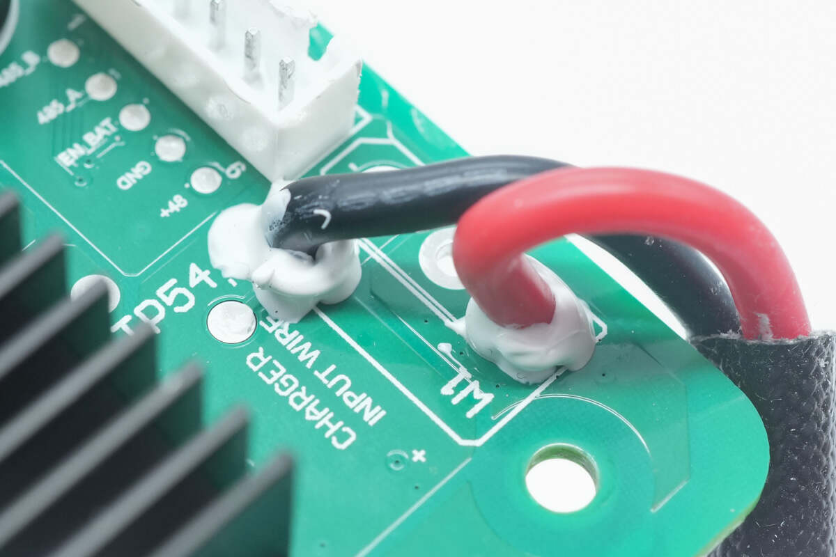
Here are the input wires connected to the DC input ports.
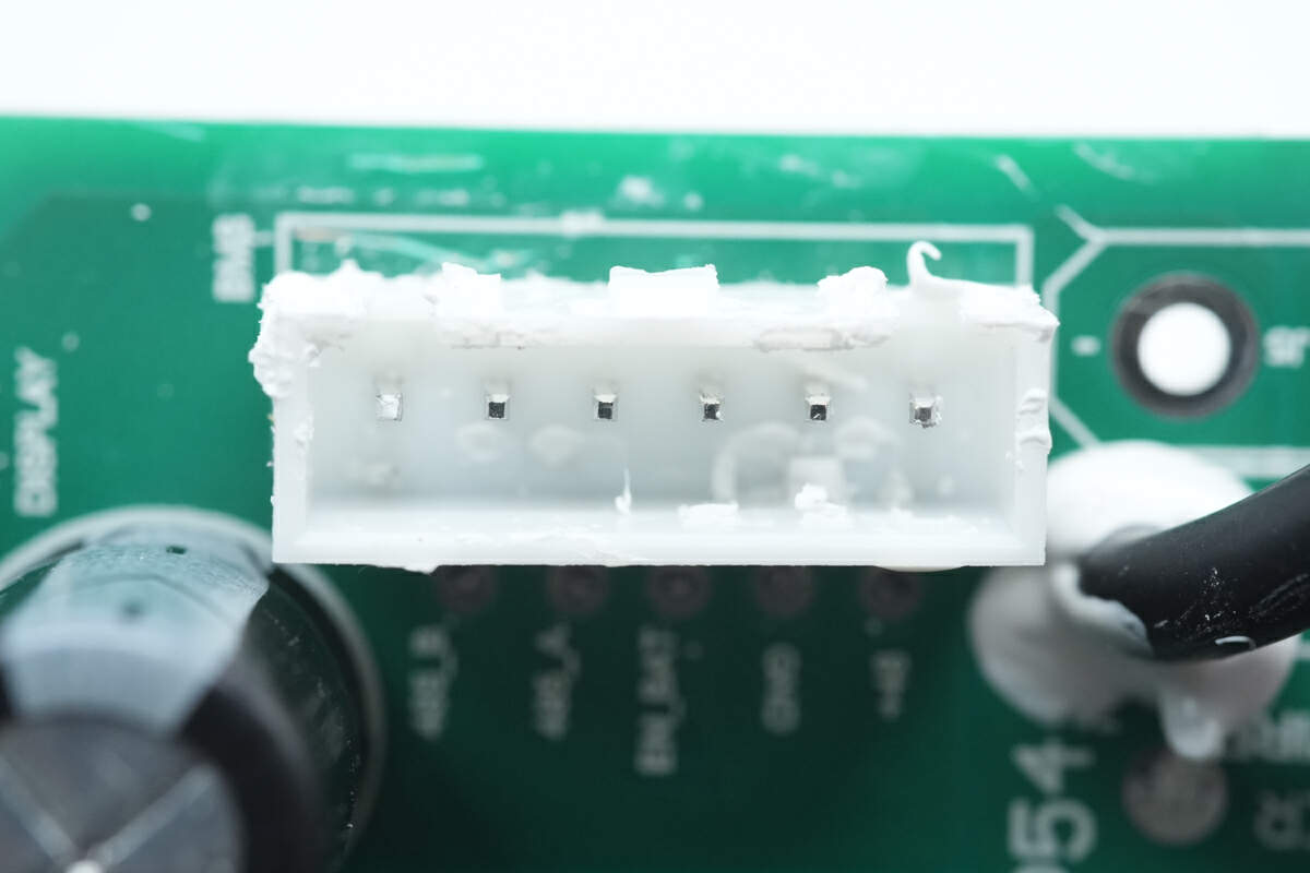
Here are the communications connectors that connect to the battery pack.
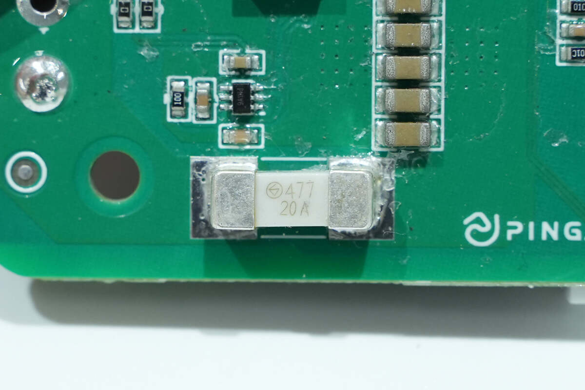
The fuse marked with 477 is from Betterfuse. 20A.
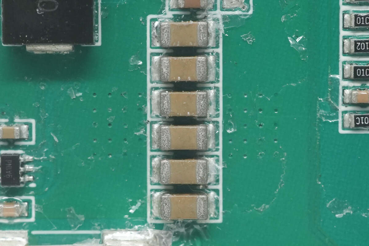
The MLCC capacitors for input filtering are connected in parallel.
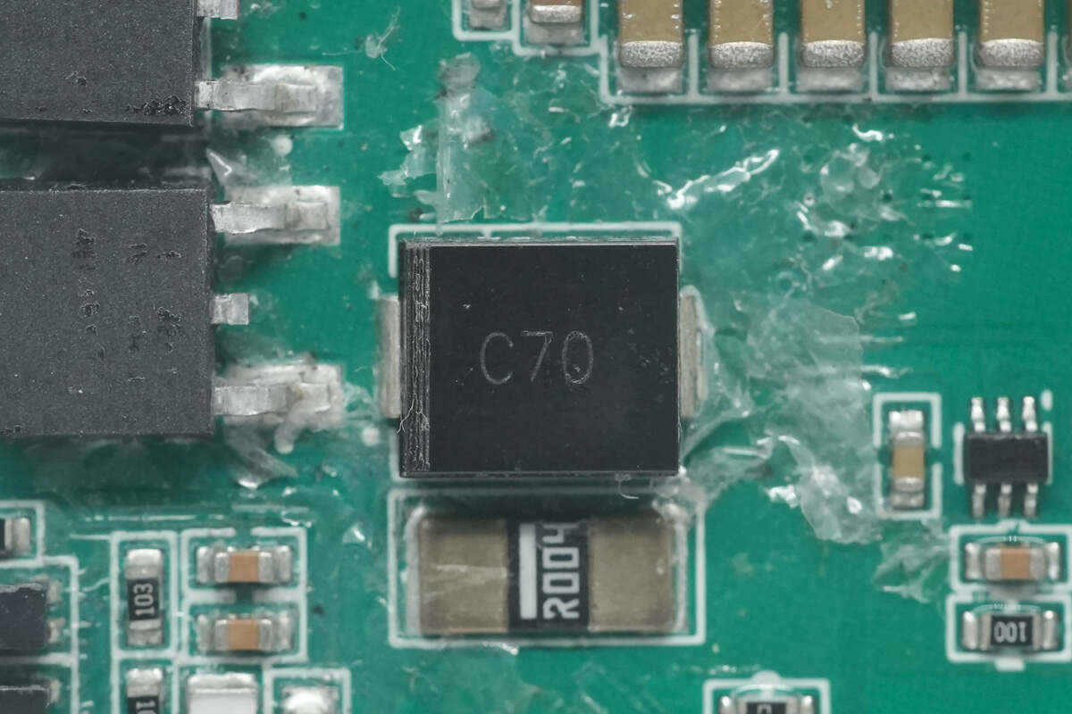
The TVS marked with C70 is used for overvoltage protection.
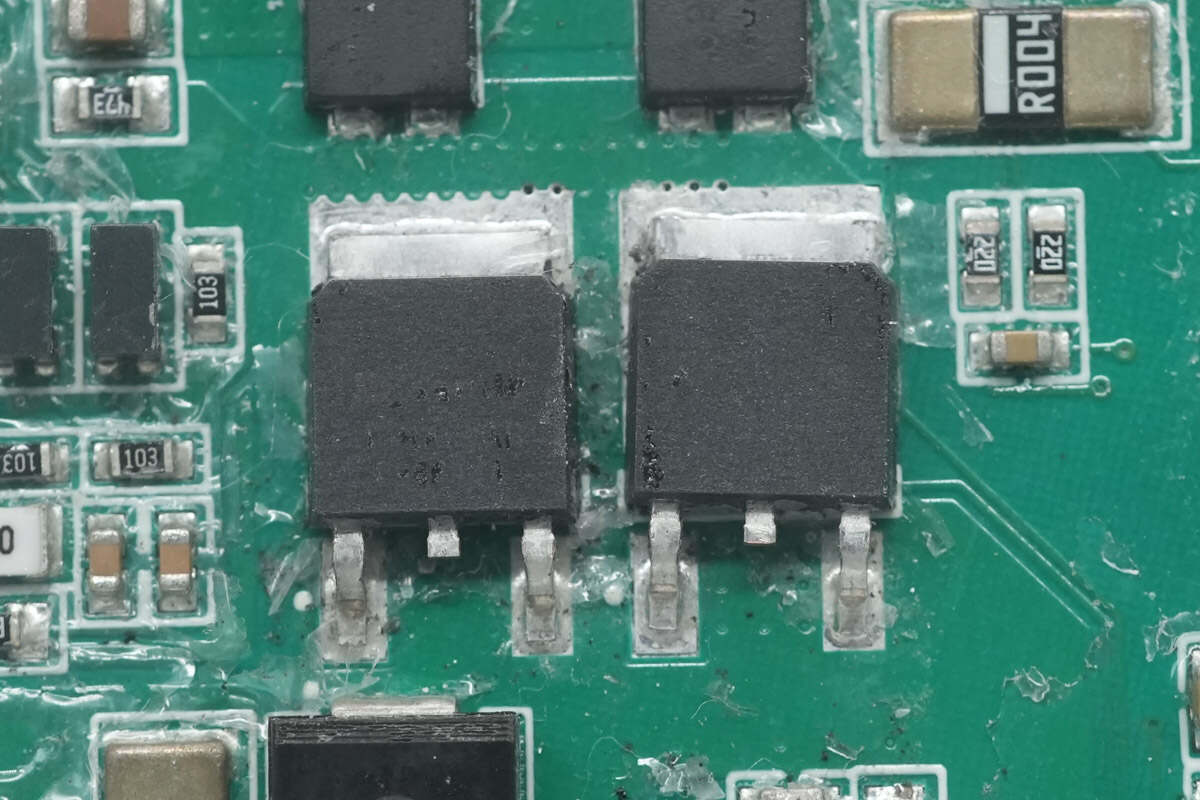
These two MOSFETs are used for power supply control.
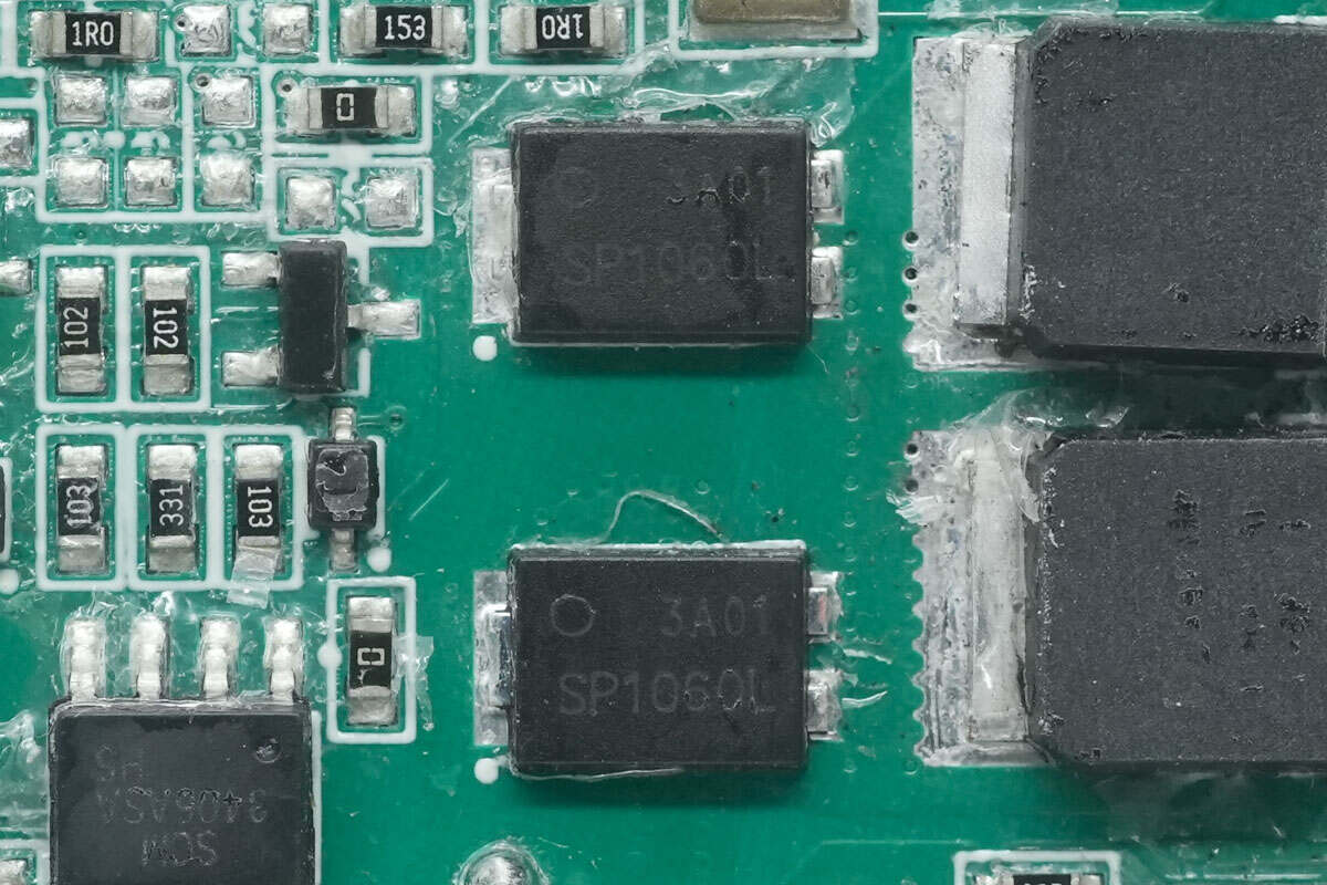
Here are two diodes.
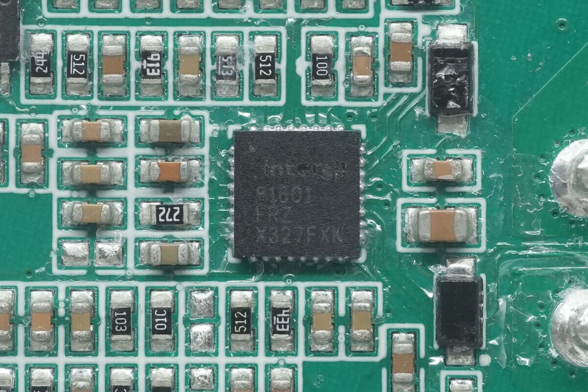
One of the synchronous buck-boost chips is from RENESAS. It supports a working voltage of 60V and is used to charge the built-in battery. Model is ISL81601.
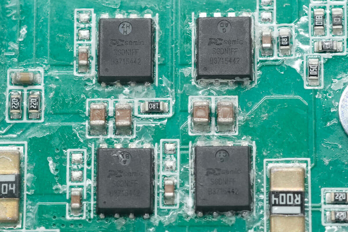
These four MOSFETs of the synchronous buck-boost chip are from PCsemic.
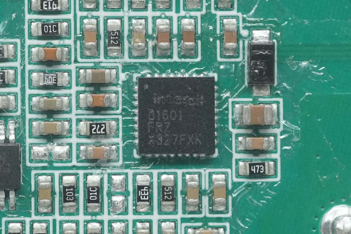
The other synchronous buck-boost chip is also from RENESAS. It is used for buck control. Model is ISL81601.
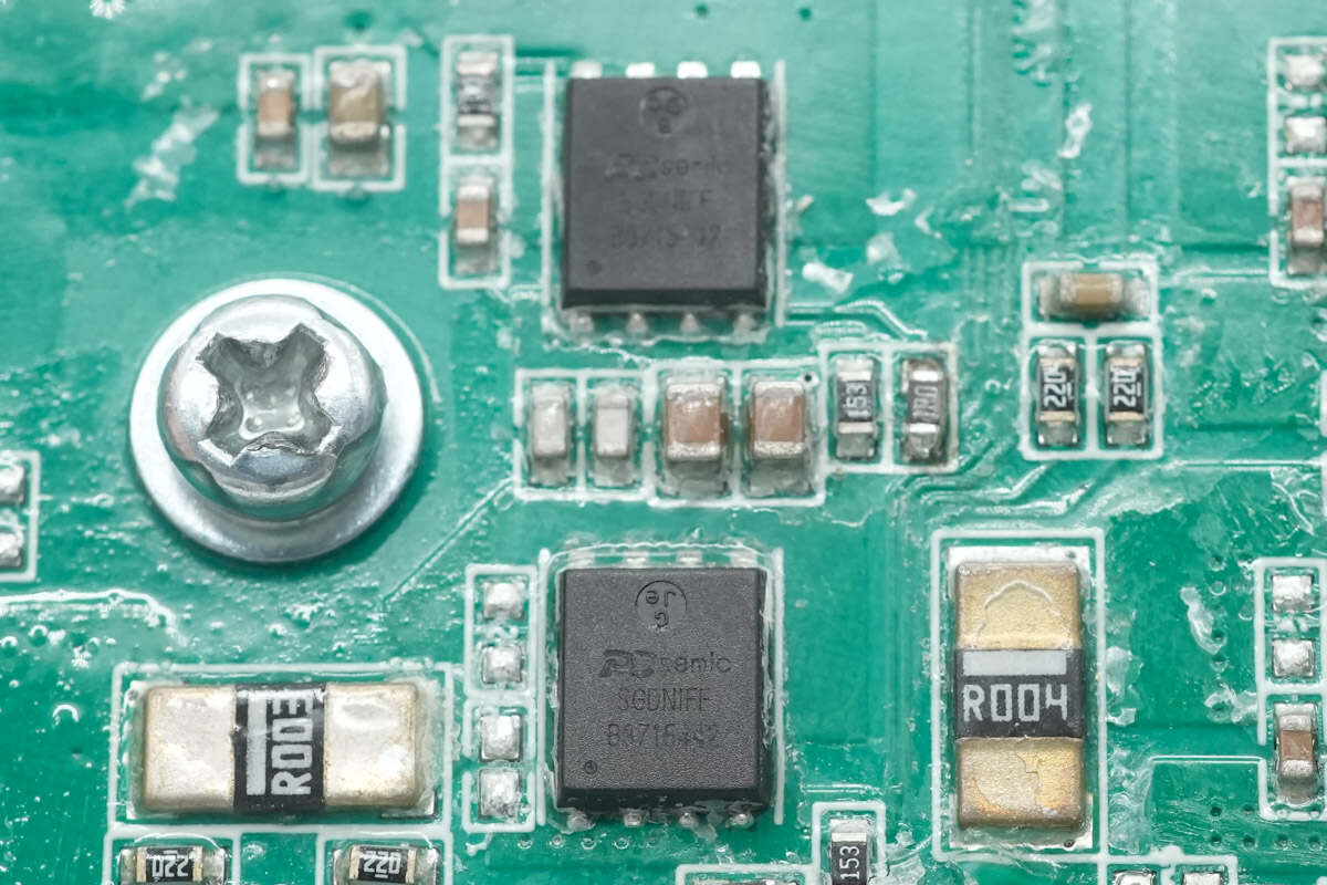
Here are the two buck MOSFETs.
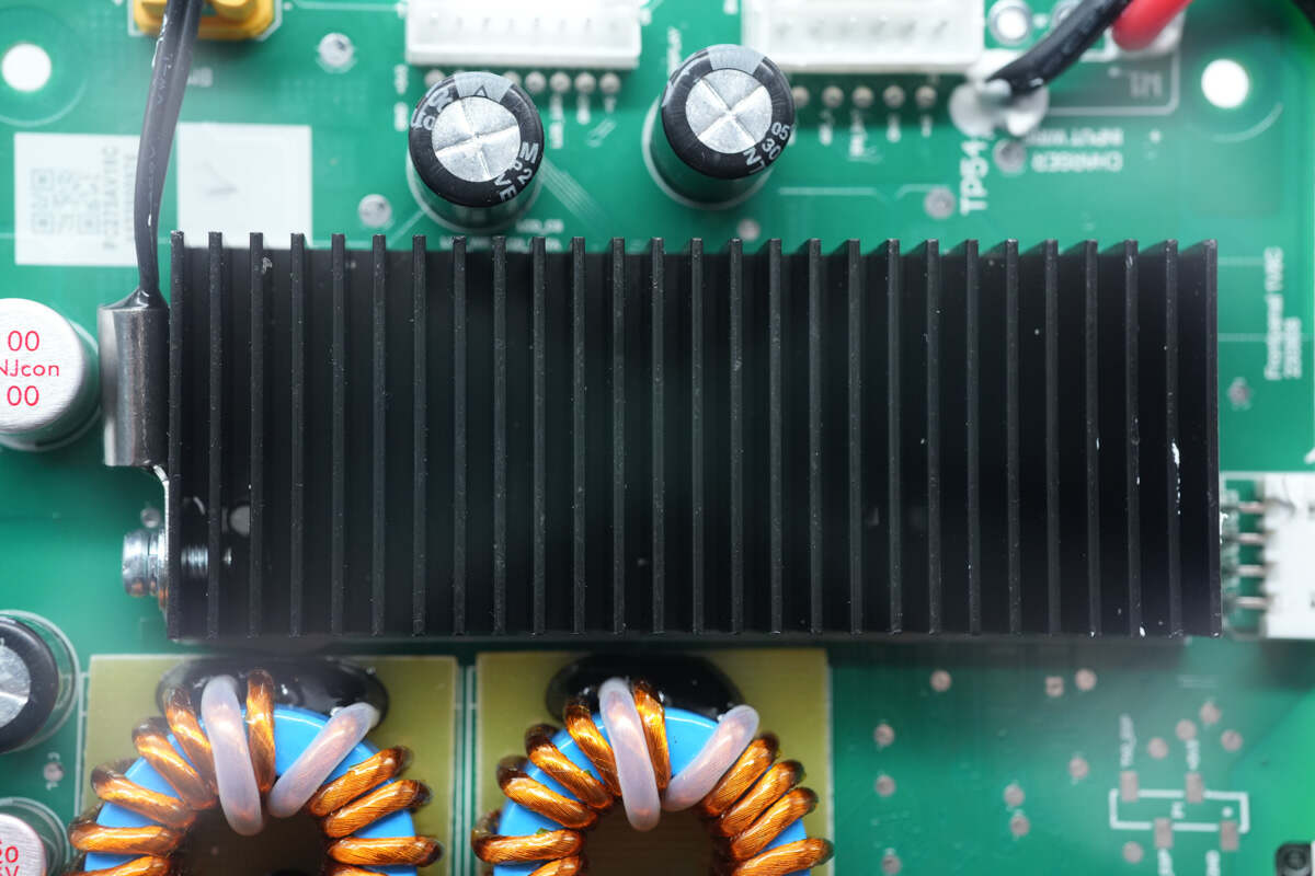
The heat sink for the MOSFETs has a thermistor on the side.
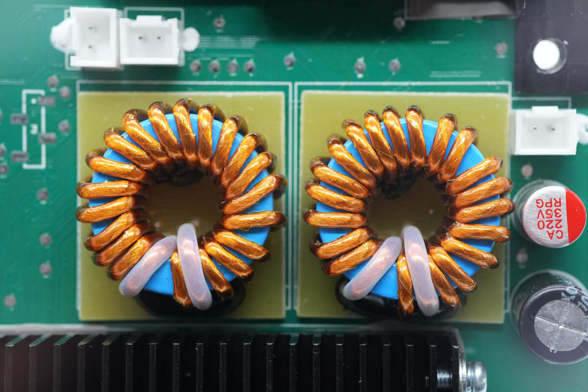
These two inductors are wounded with magnetic rings and they're also insulated with bakelite.
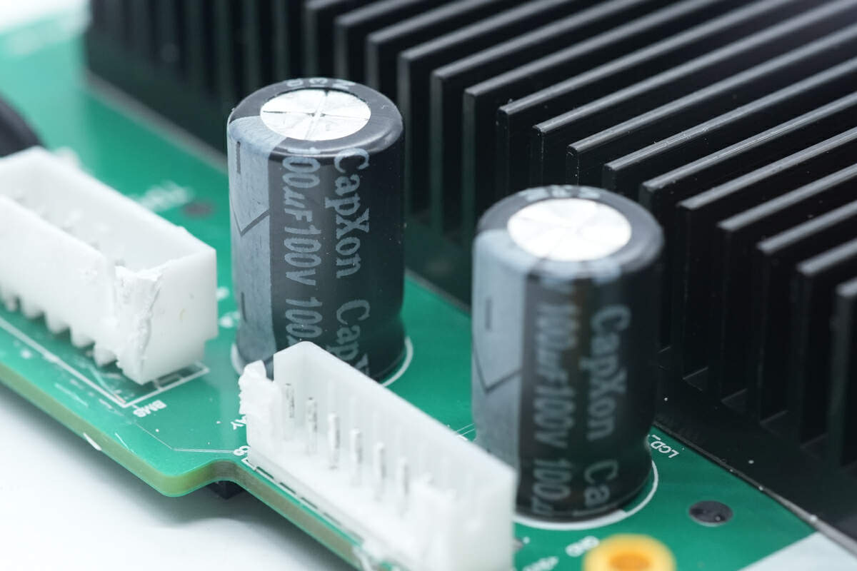
These two electrolytic capacitors for input filtering are from CapXon. 100μF 100V.
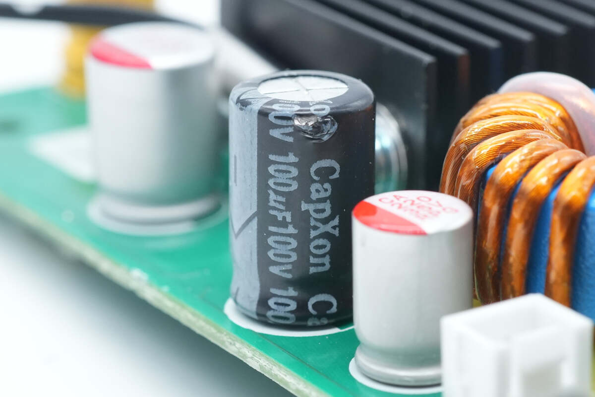
There is also an electrolytic capacitor for input filtering with the same specifications.
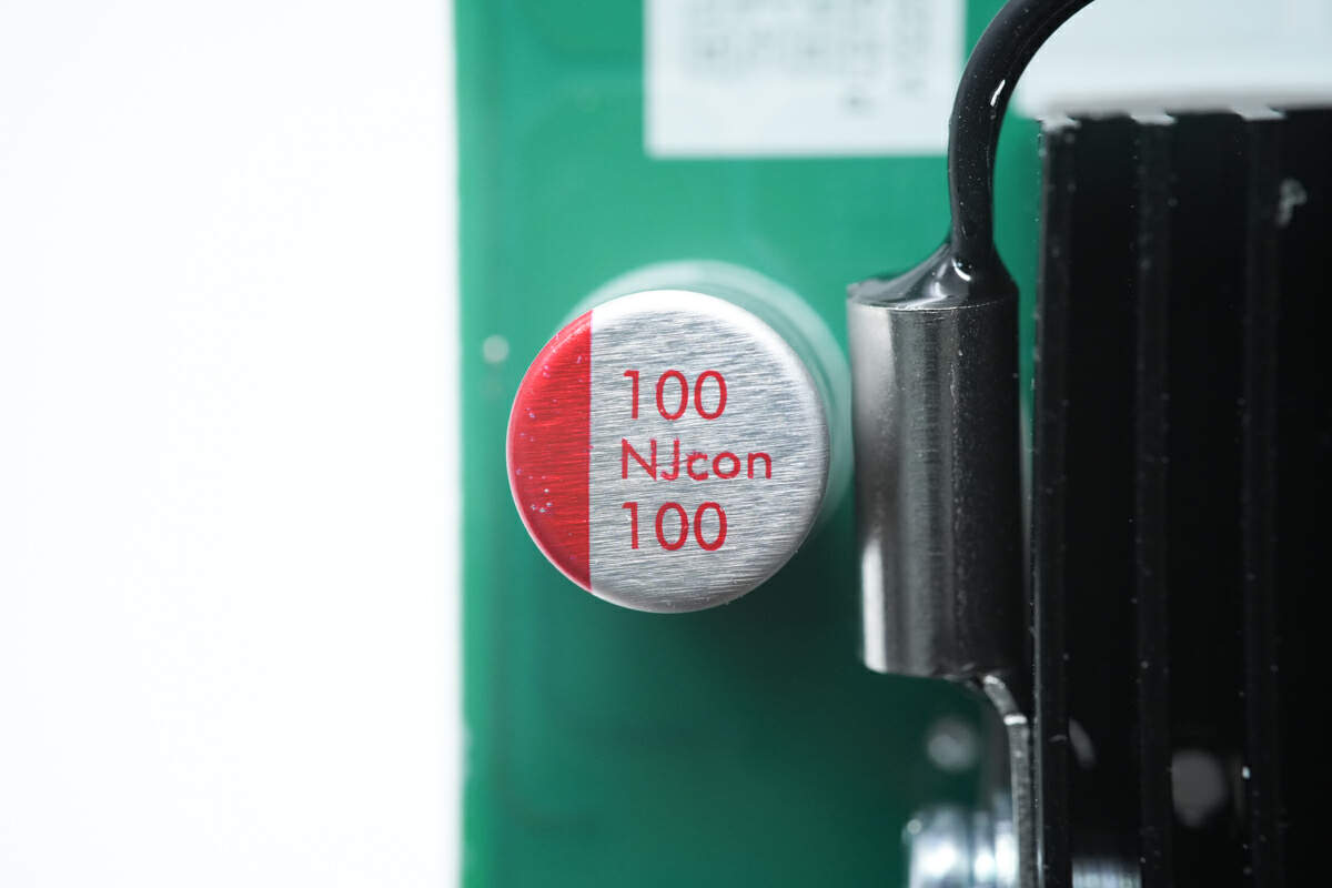
The solid capacitor is from Winner. 100μF 100V.
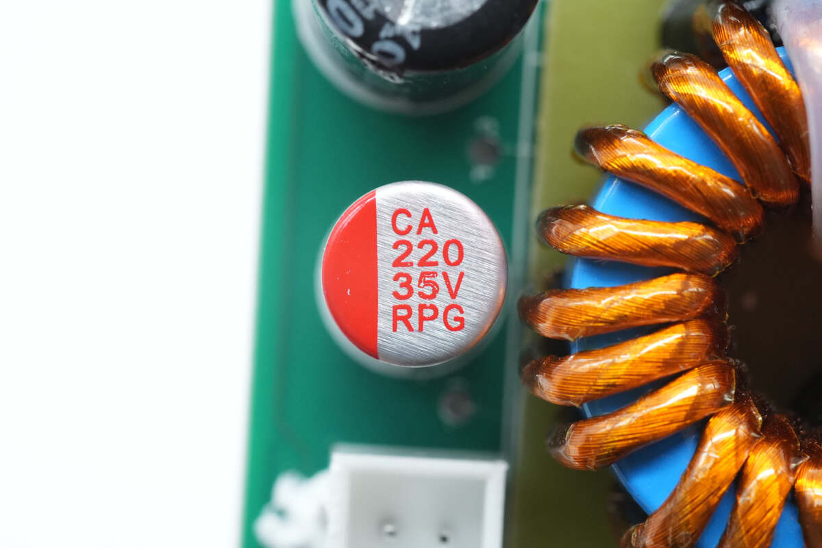
There is another solid capacitor. 220μF 35V.
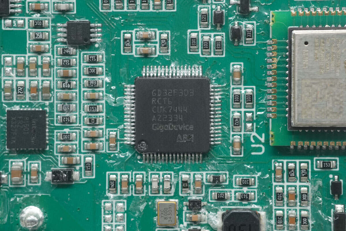
The MCU is from GigaDevic. Its frequency reaches 120MHz. It has a built-in Cortex-M4 core with 256KB FLASH and 48KB SRAM. Model is GD32F303RCT6.
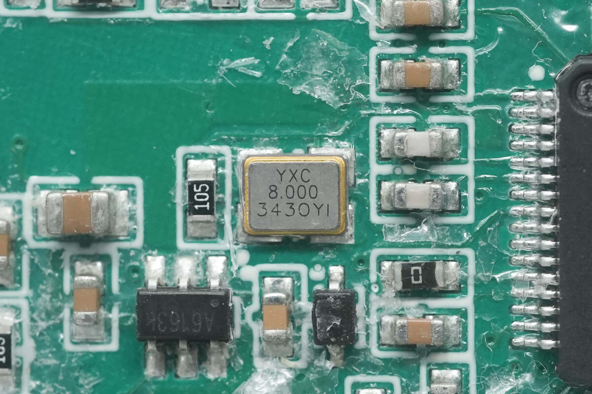
This is the 8.000MHz crystal oscillator.
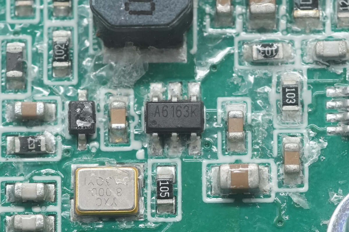
The buck chip is marked with A6163K.
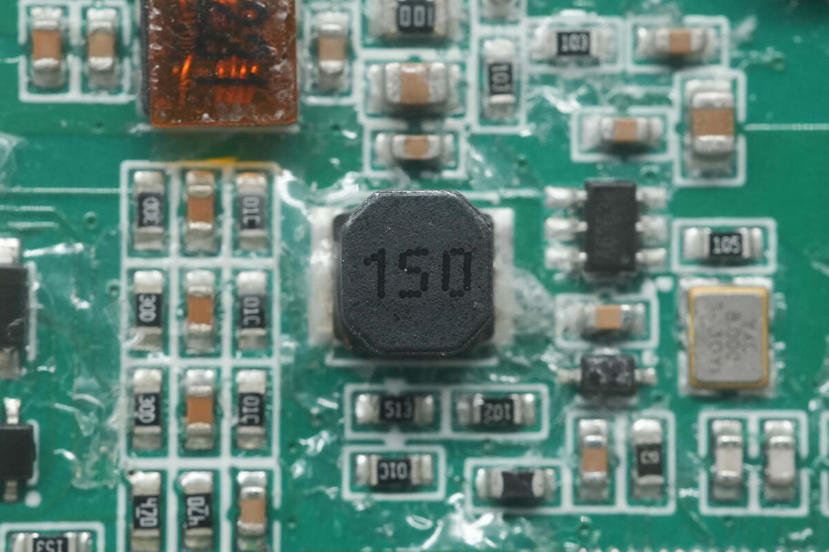
Here is the SMD buck inductor. 15μH.
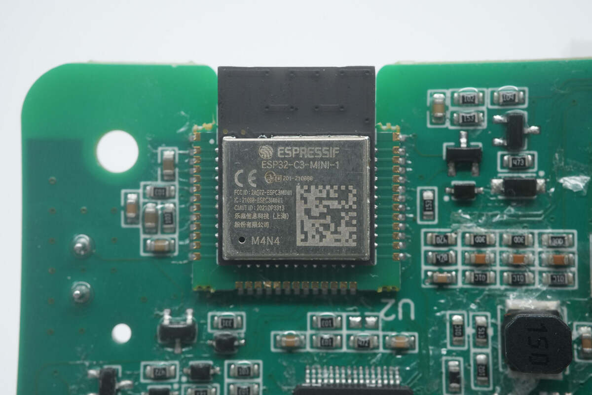
The wireless communication module is from ESPRESSIF. Model is ESP32-C3-MINI-1.
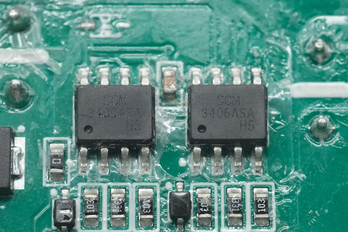
These two chips for transceivers are from MORNSUN. They are used for RS-485 communication to communicate with the battery pack. Model is SCM3406ASA.
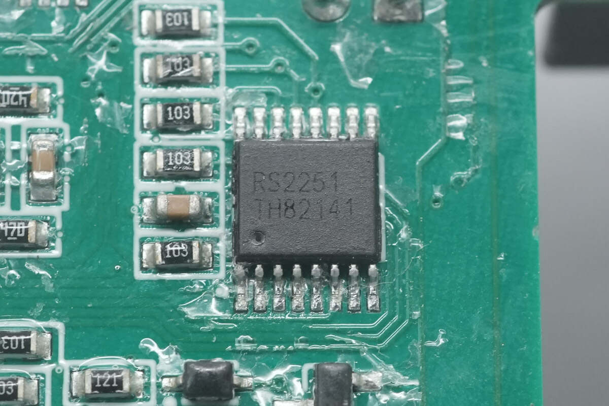
The 8-channel switch used for signal acquisition switching is from Runic. Model is RS2251.
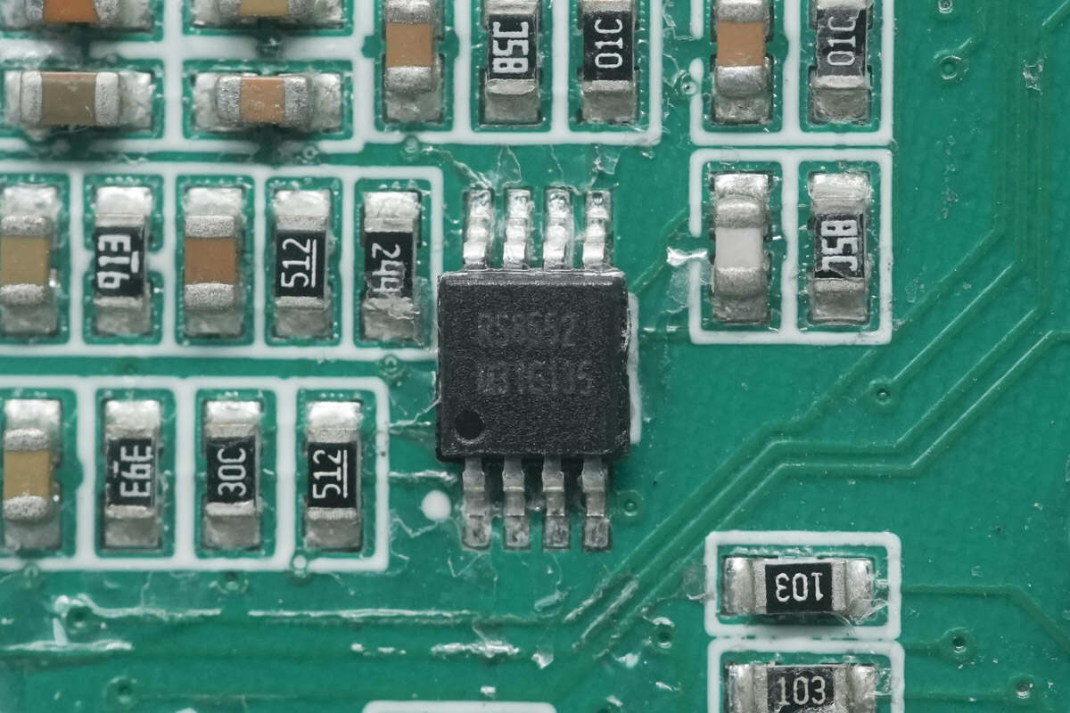
The Op-Amp used for signal acquisition and amplification is from Runic. Model is RS8552.
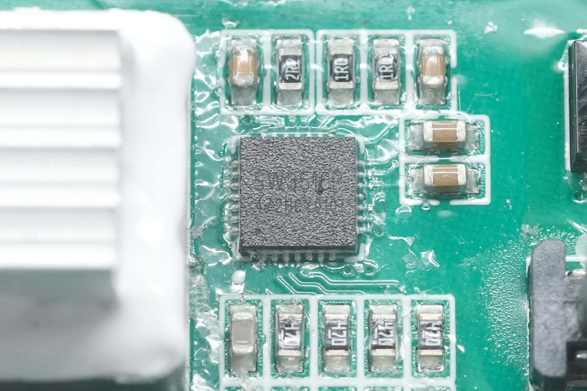
Both two buck controllers of the two USB-C ports are from iSmartWare. They support charging of any USB-C and USB-A ports and dual-port independent current limiting. Model is SW3516P.
The buck controller integrates a 5A high-efficiency synchronous buck converter. It supports PPS, PD, QC, AFC, FCP, SCP, PE, SFCP, and other fast-charging protocols. It can output up to PD 100W. It also supports CC/CV modes.
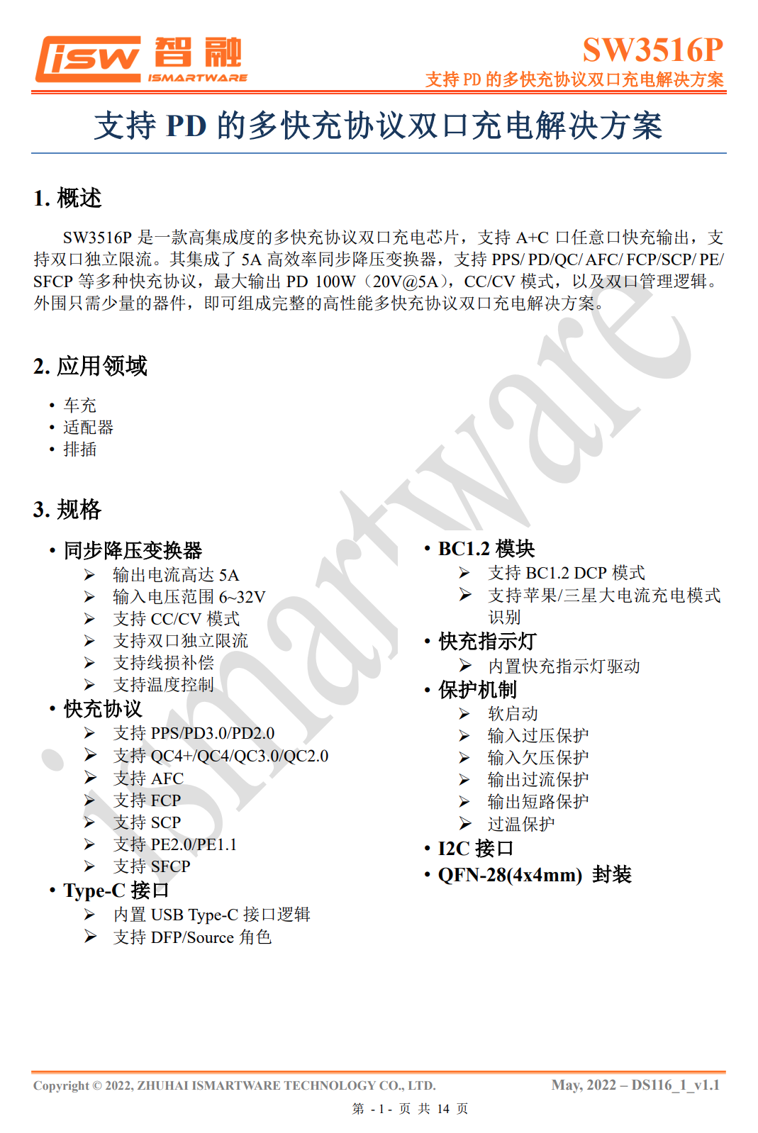
Here is all the information about the iSmartWare SW3516P.
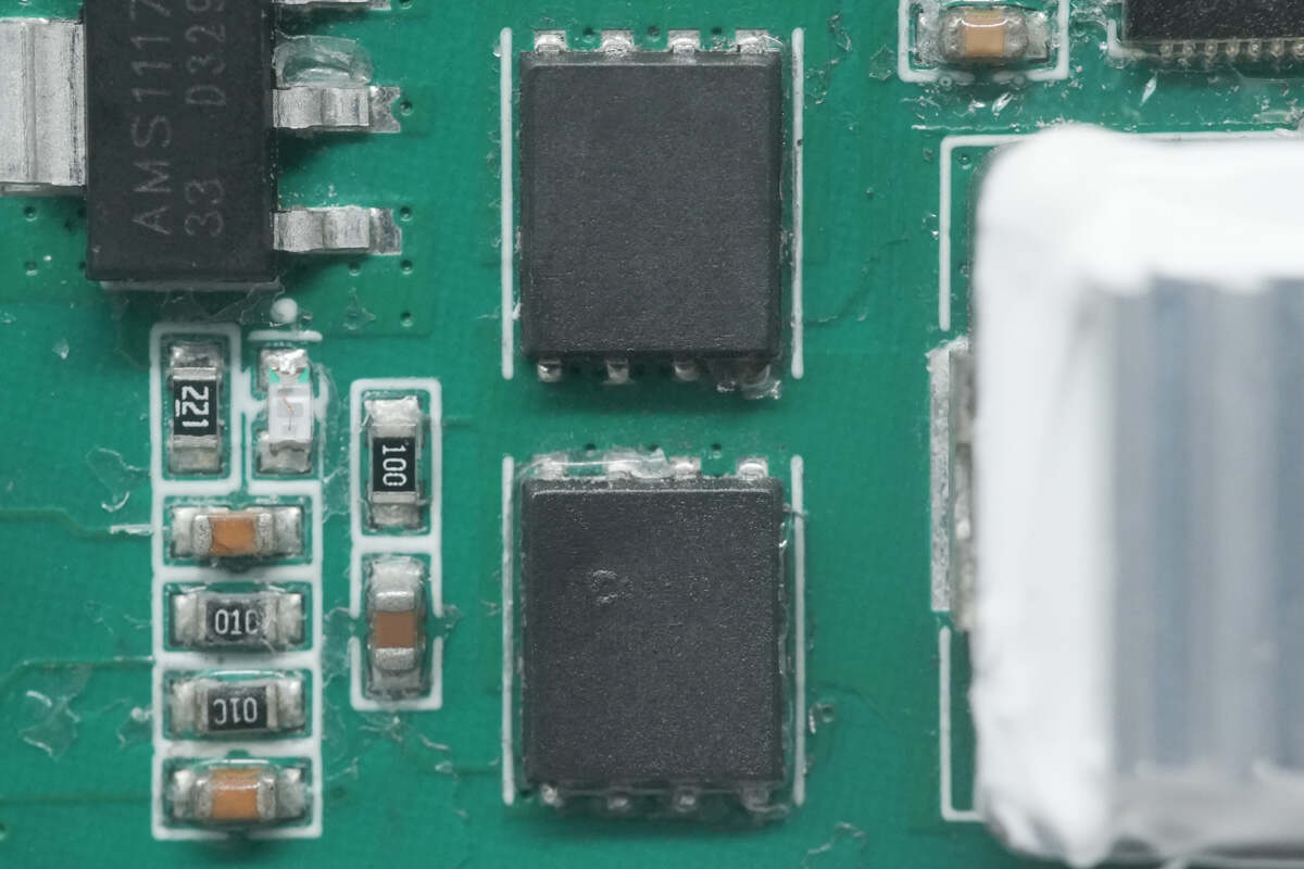
There are two synchronous buck MOSFETs.
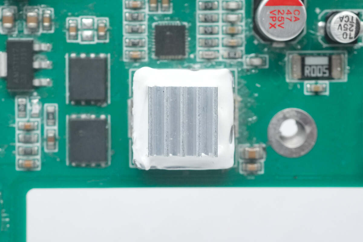
The heat sink of the buck inductor is glued on.
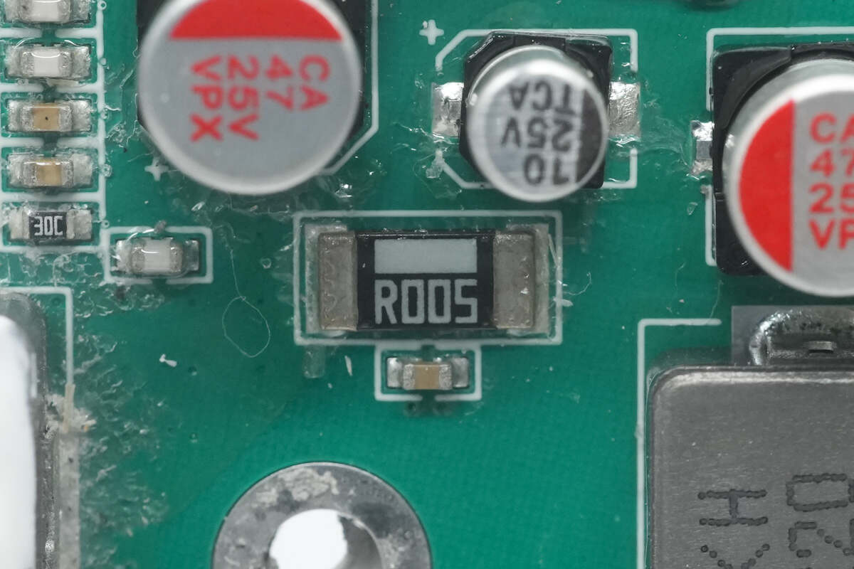
The sampling resistor is used to detect the output current. 5mΩ.
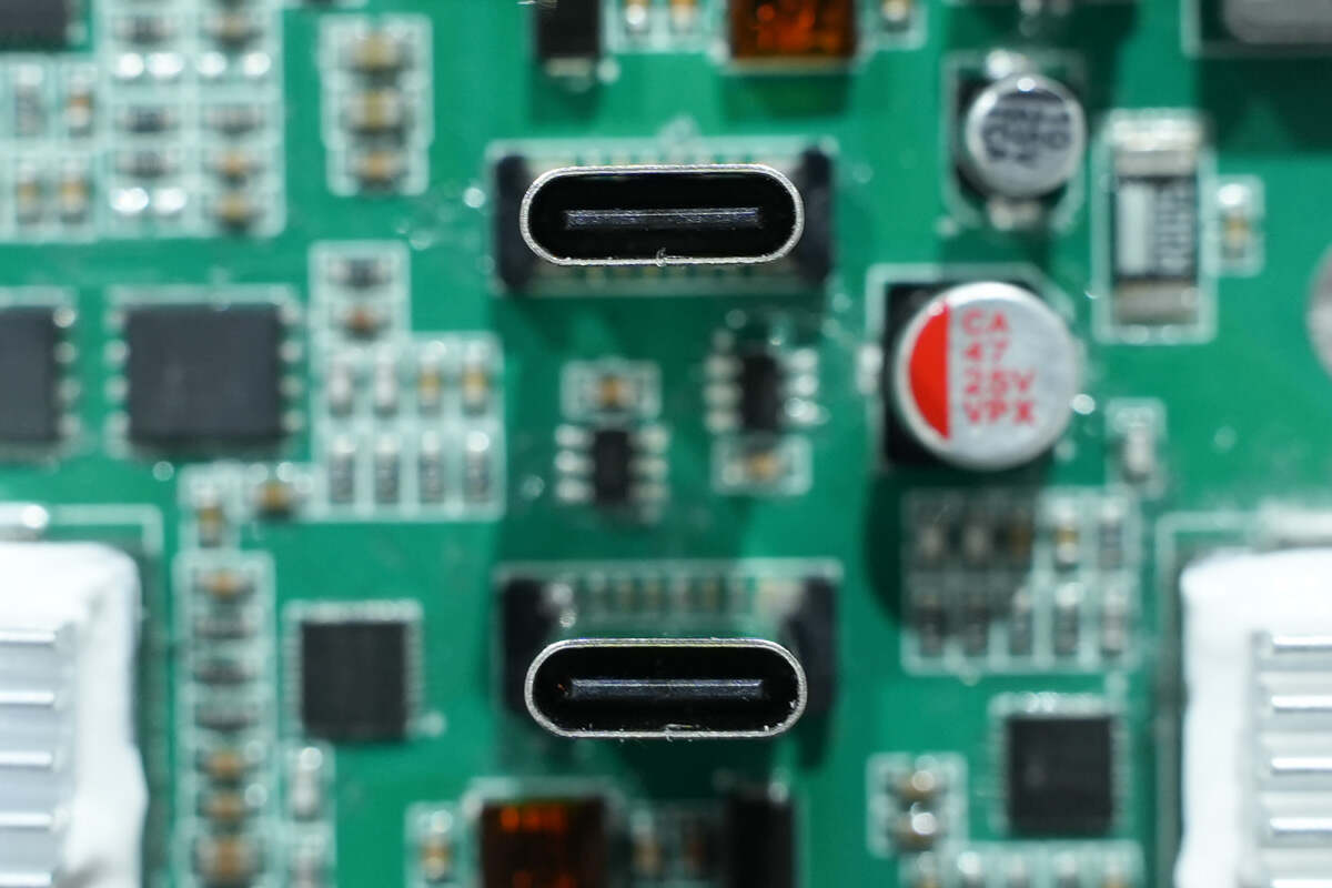
Here are two USB-C sockets.
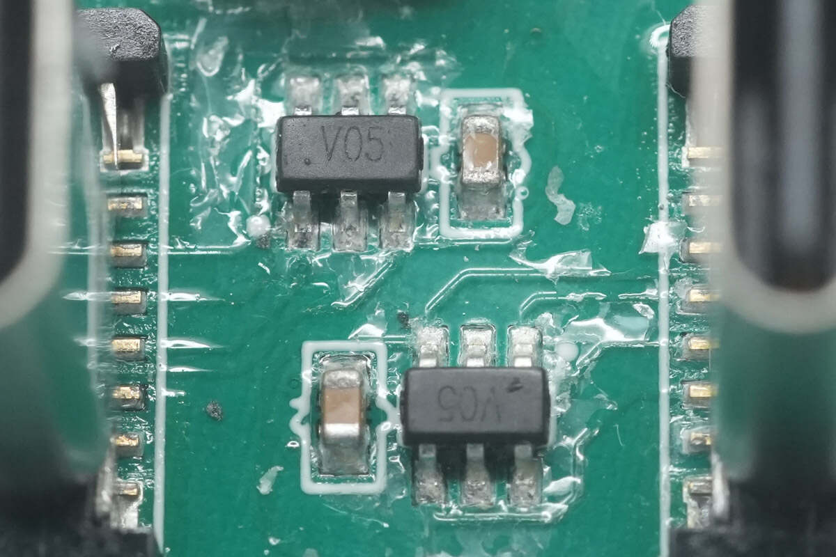
There are two TVSs between the two USB-C sockets for electrostatic protection.
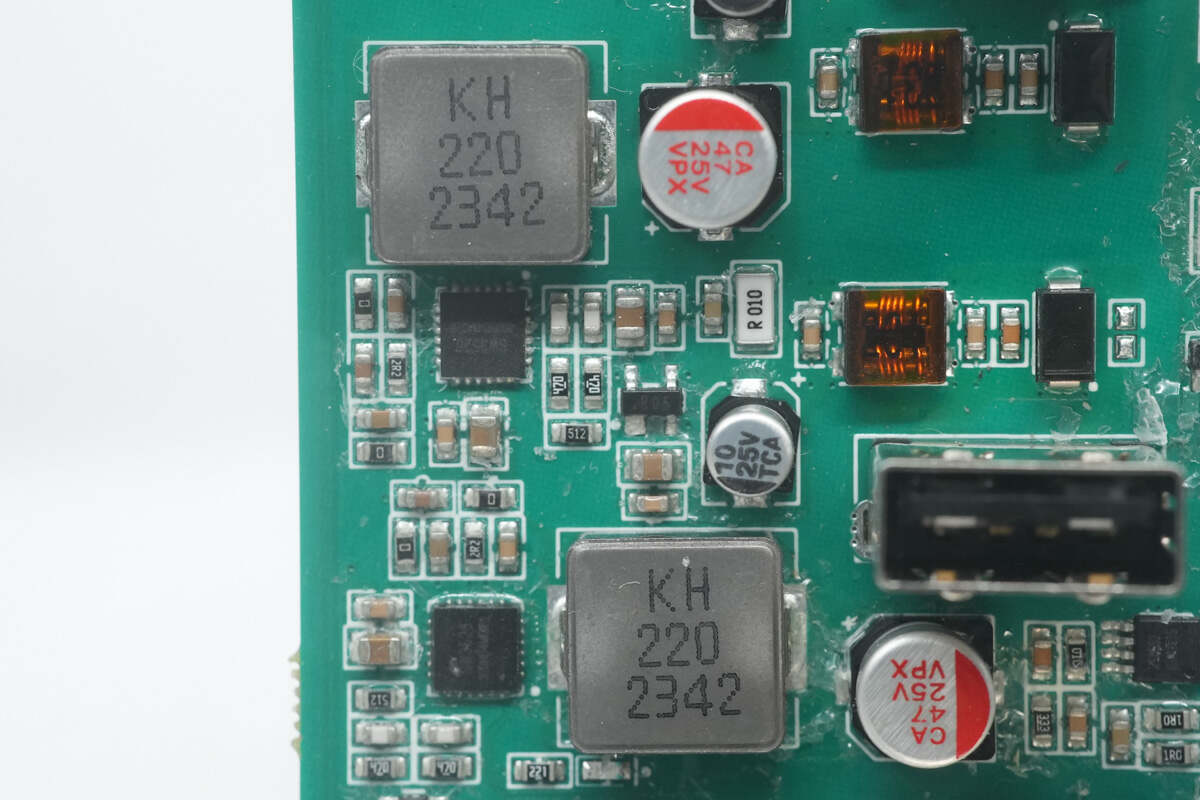
Here is the buck circuit of the USB-A ports.
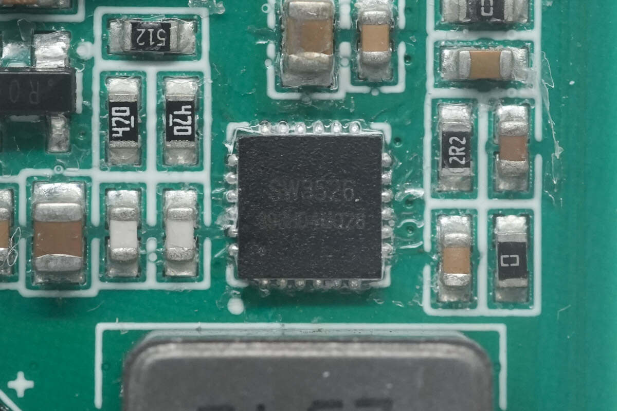
The buck controller of the USB-A ports is also from iSmartWare. It integrates a 3.5A high-efficiency synchronous rectifier buck converter. It supports CC/CV modes. It supports PPS, PD, QC, AFC, FCP, SCP, PE, SFCP, and other fast-charging protocols. Model is SW3526.
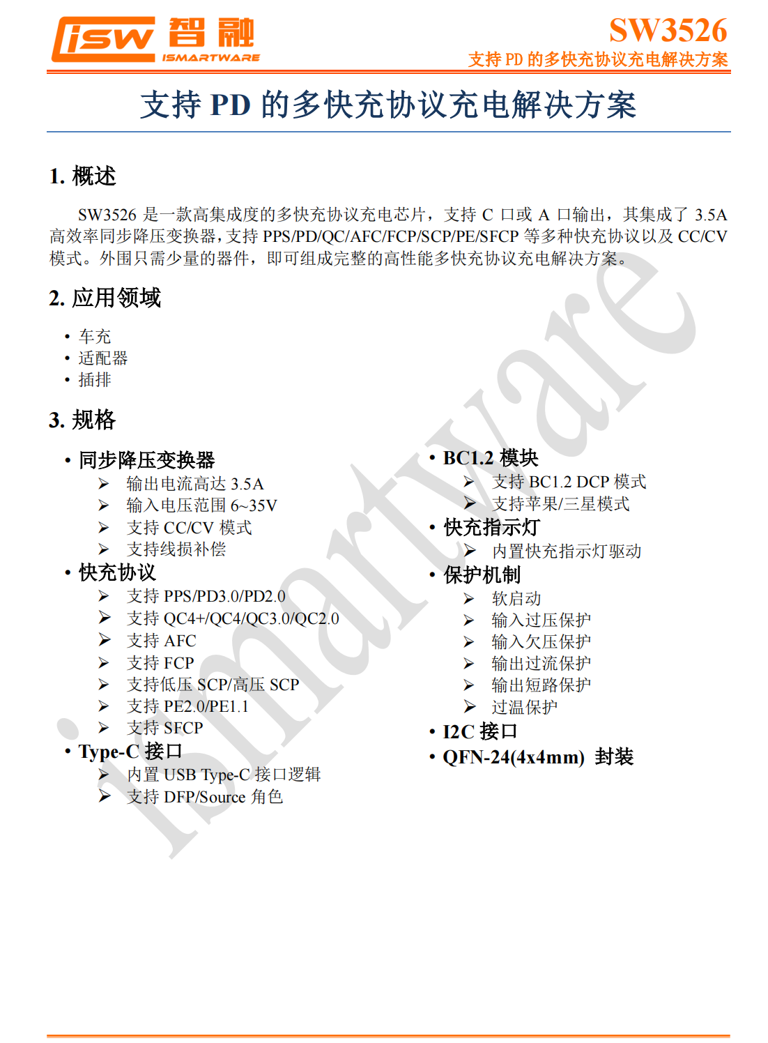
Here is all the information about the iSmartWare SW3526.
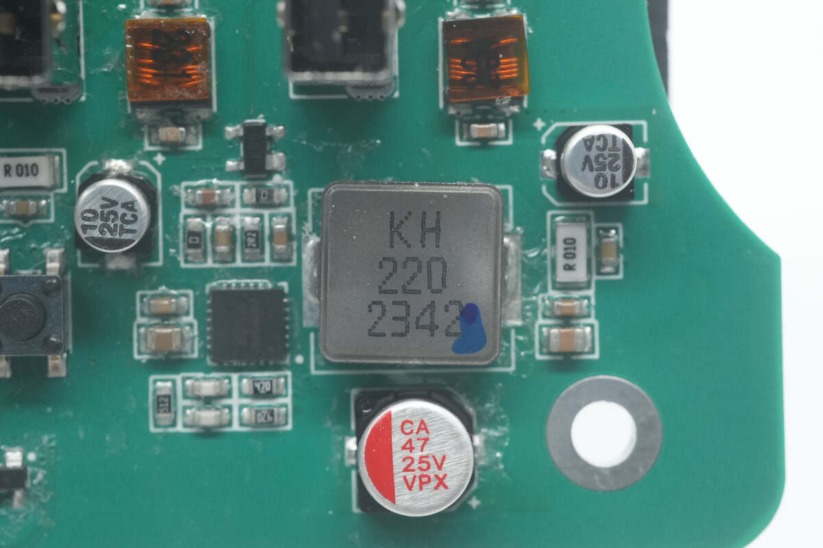
Here is the buck inductor. 22μH.
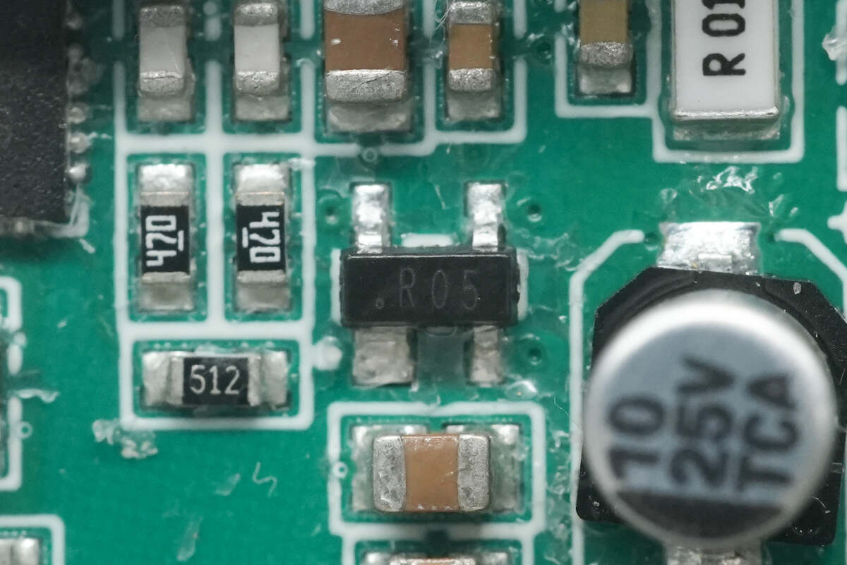
The TVS is used for overvoltage protection.
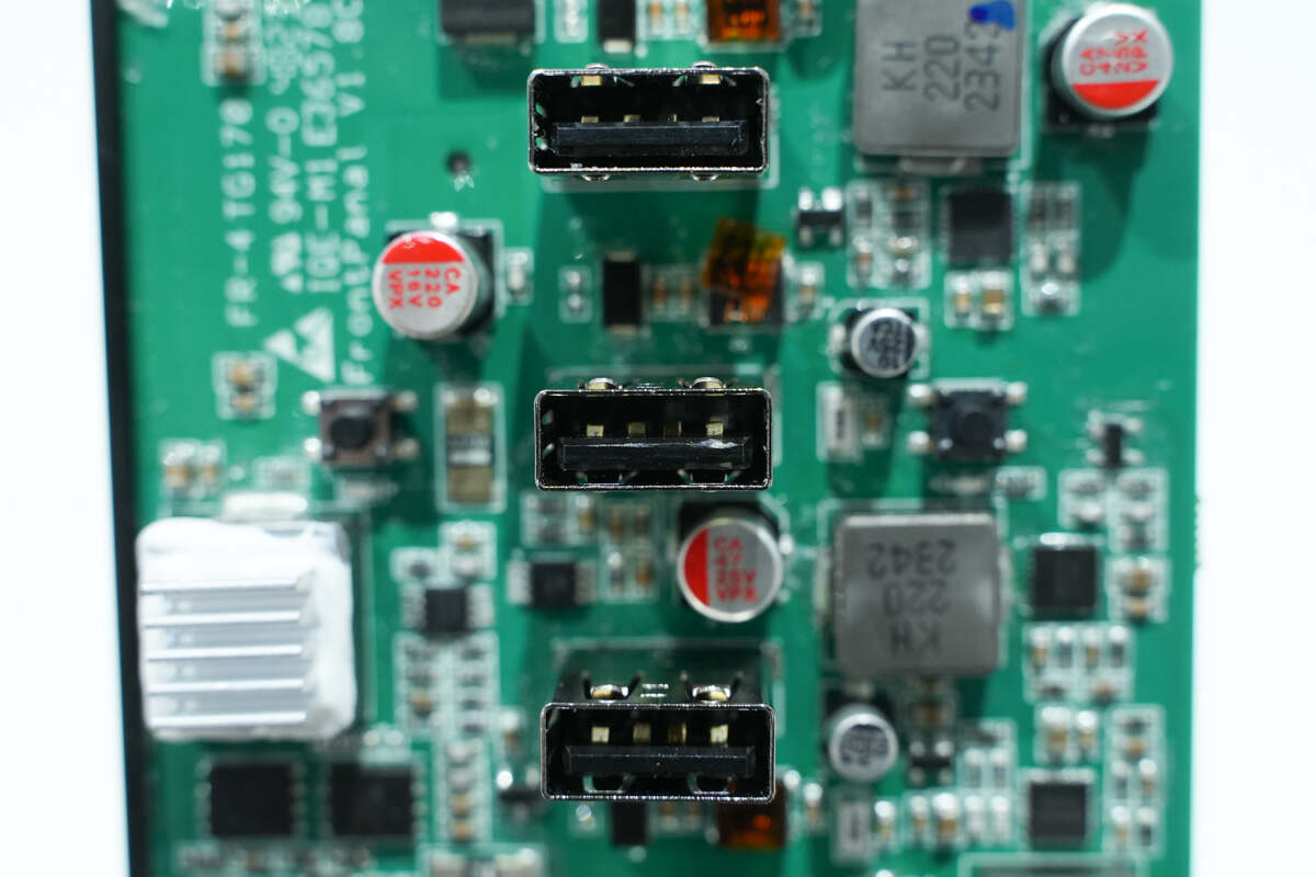
There are three USB-A sockets.
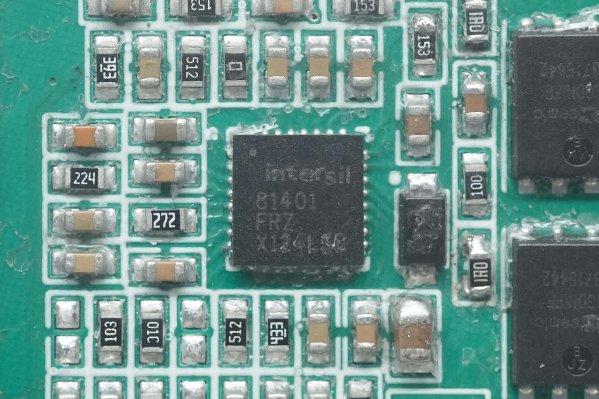
The synchronous buck controller of the car port is from RENESAS. It supports a working voltage of 40V. Model is ISL81401.
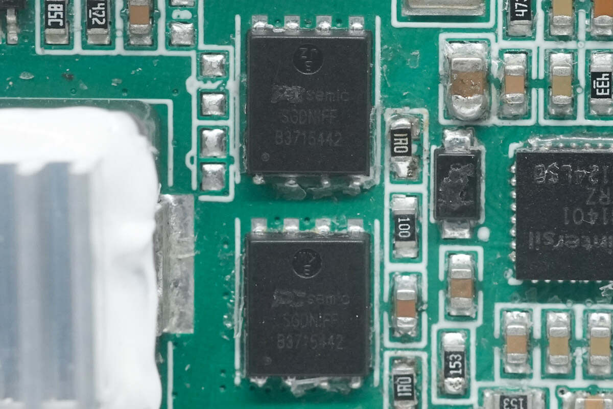
There are two buck MOSFETs.
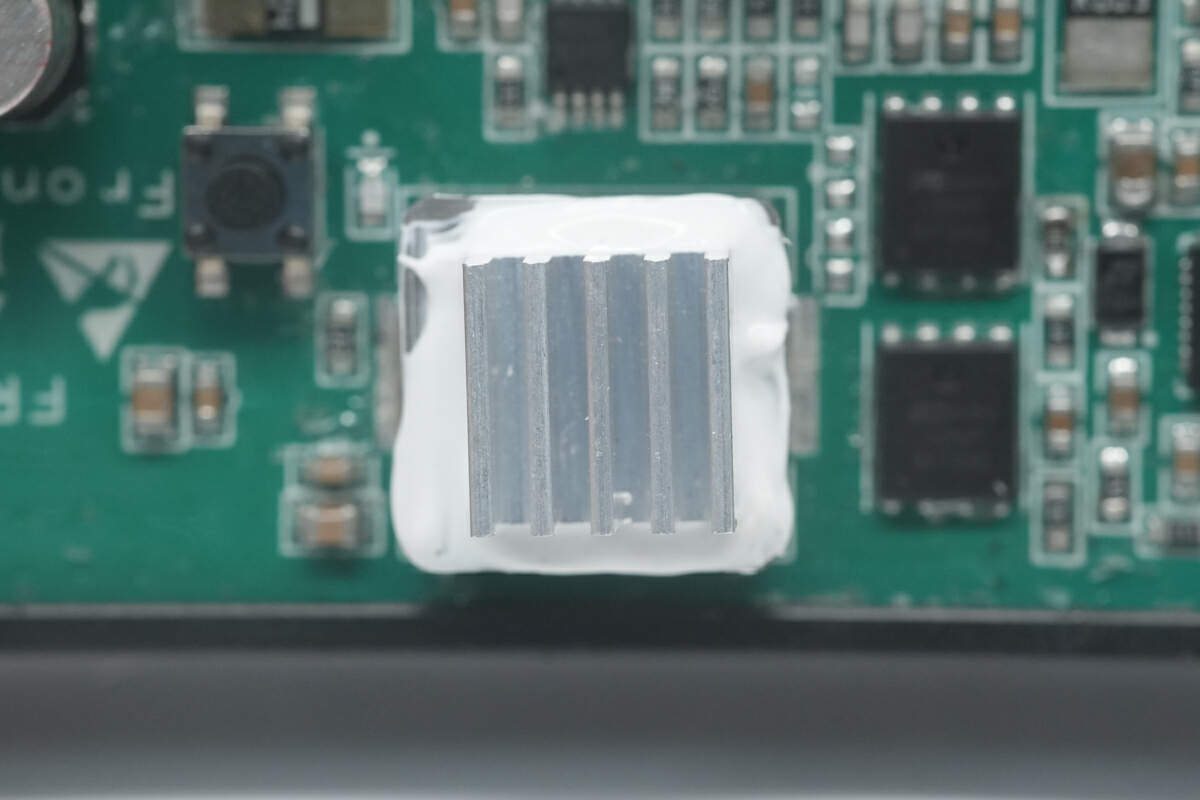
The heat sink of the buck inductor is glued on.
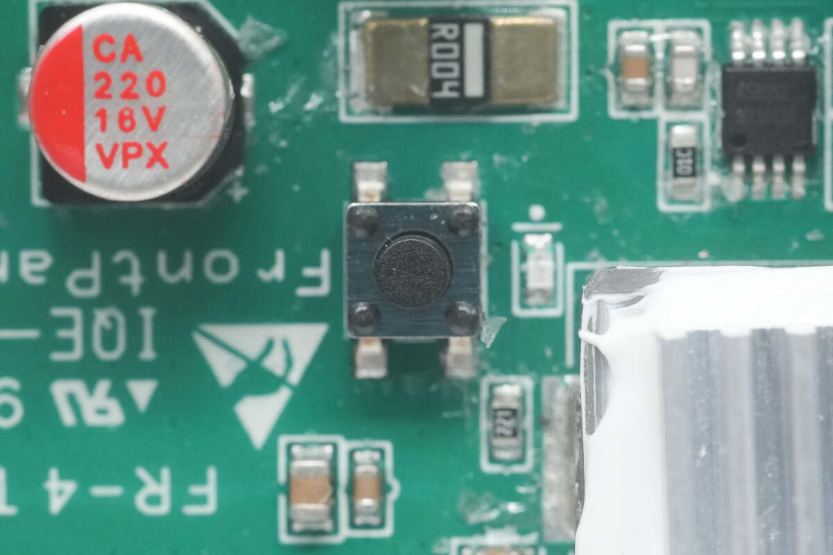
There is a button next to the buck inductor for DC output control. And there is an LED indicator light on the right side to indicate the output status.
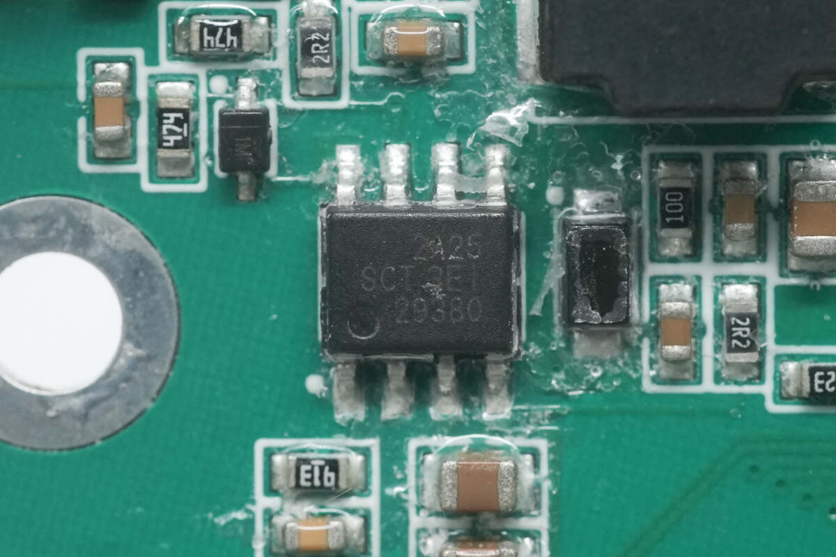
The buck chip is from Silicon. It integrates MOSFET inside. It supports 5.5-100V input voltage and 2A output current. Model is SCT2A25.
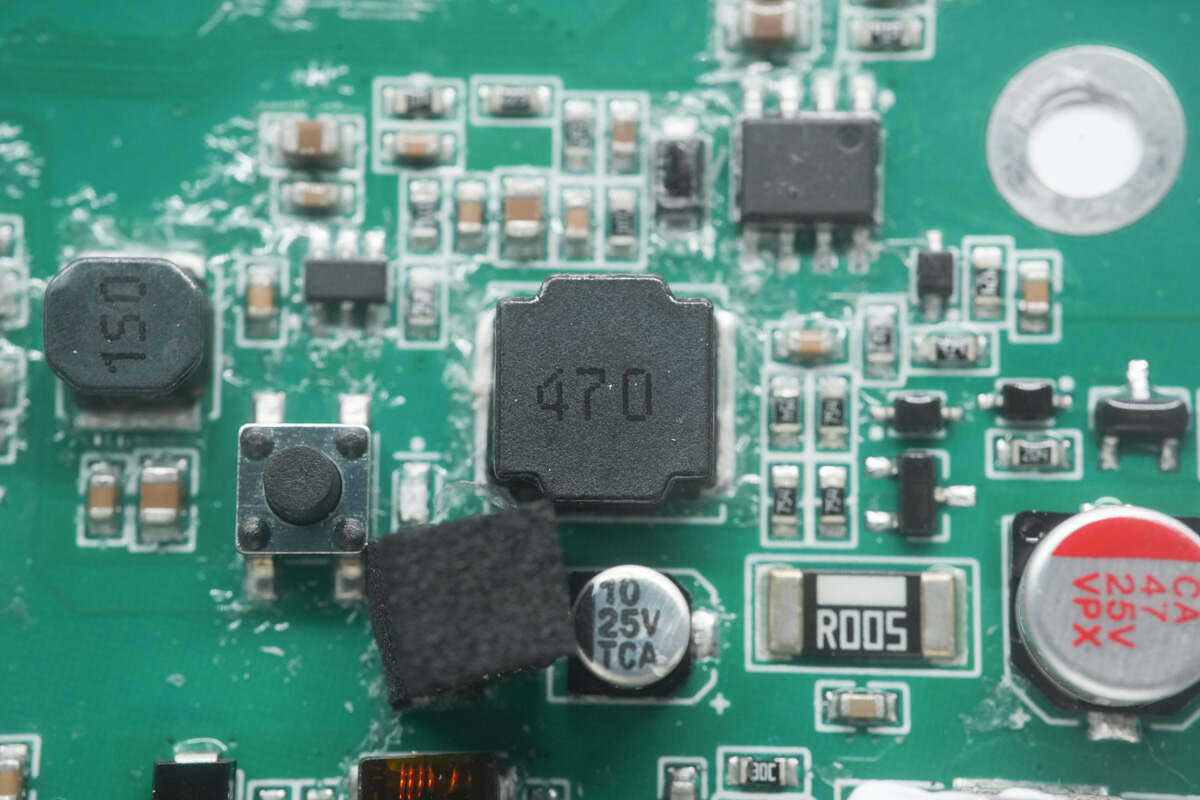
There is the buck inductor. 47μH.
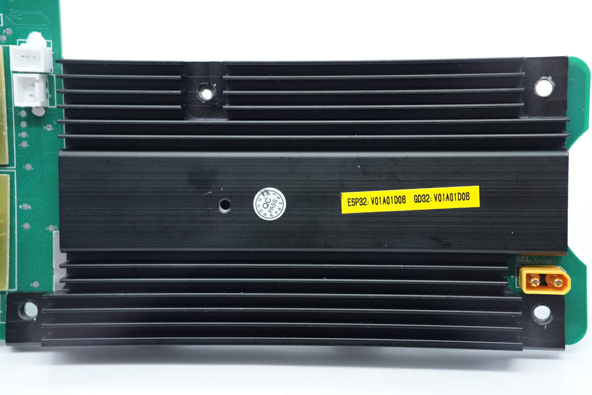
The back of the synchronous buck MOSFET is covered with a large heat sink.
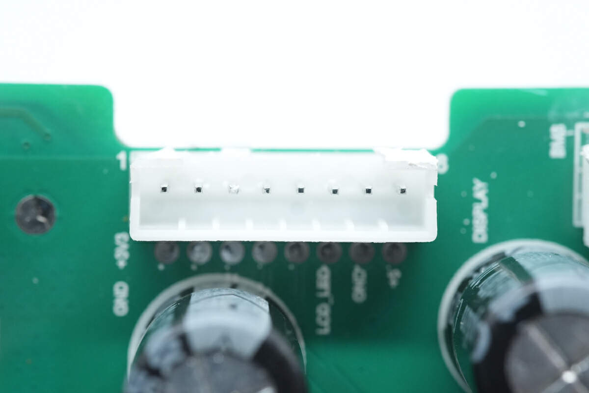
This is the connector of the display.
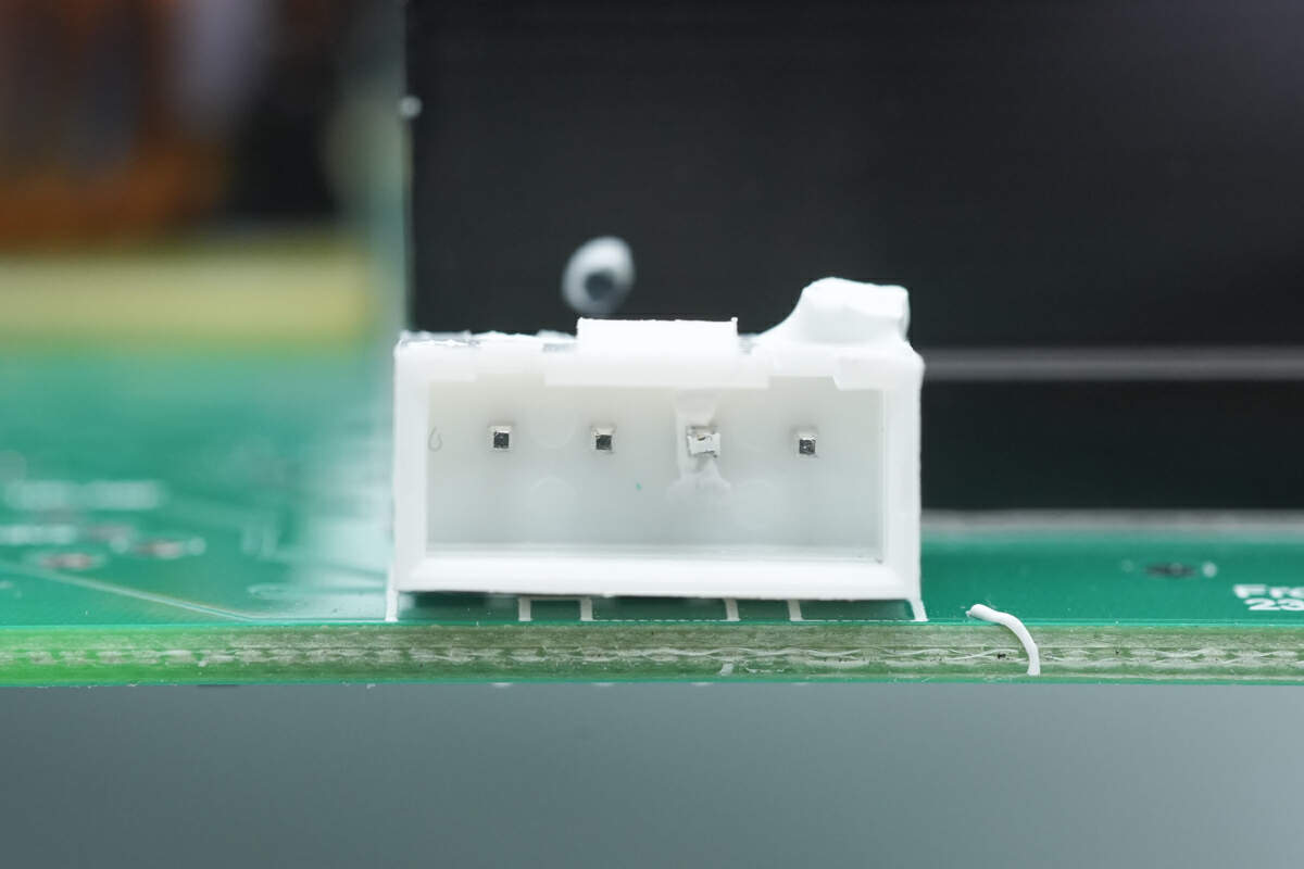
This is the connector of the light bar.
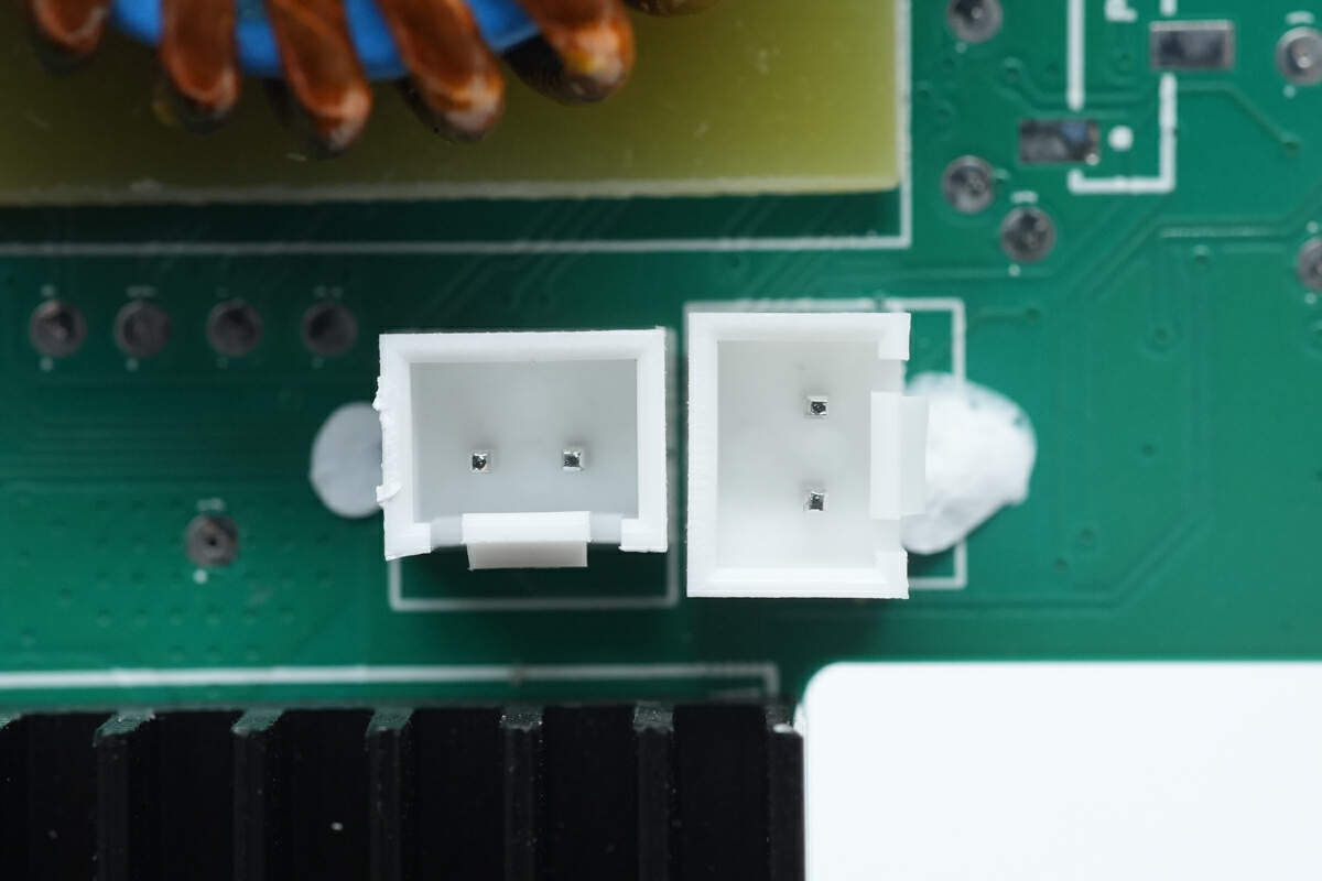
These are the connectors of the thermistors.
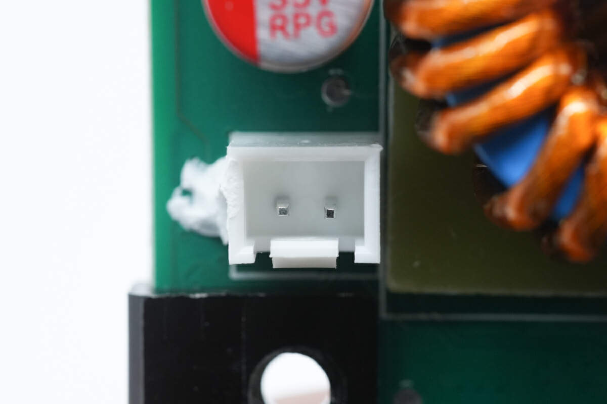
This is also a connector of the thermistor.
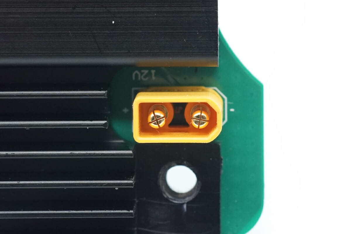
This is the socket of the car port.
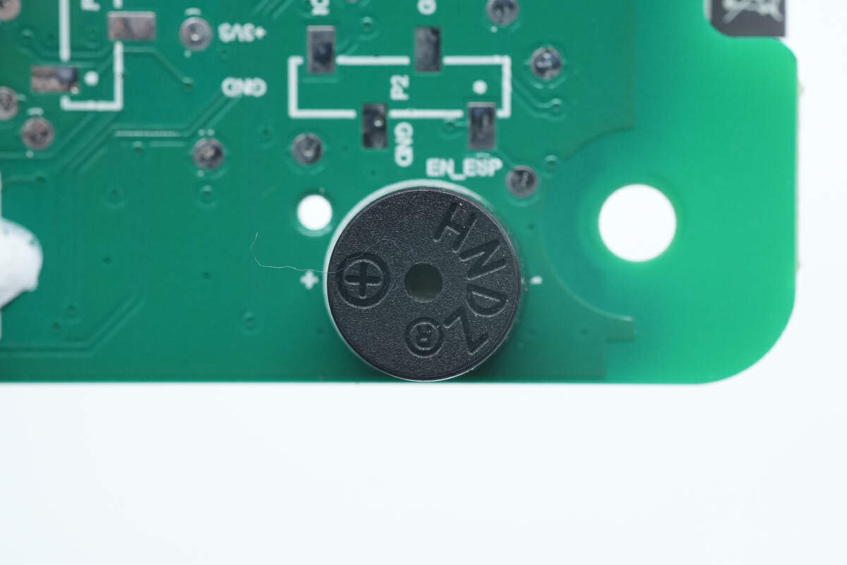
The buzzer is used for reminder.
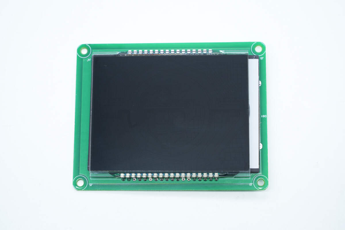
The LCD is soldered on the front of the display module.
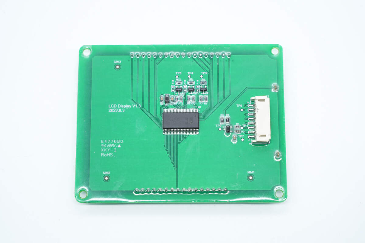
The driver chip and socket are on the back of the display module.
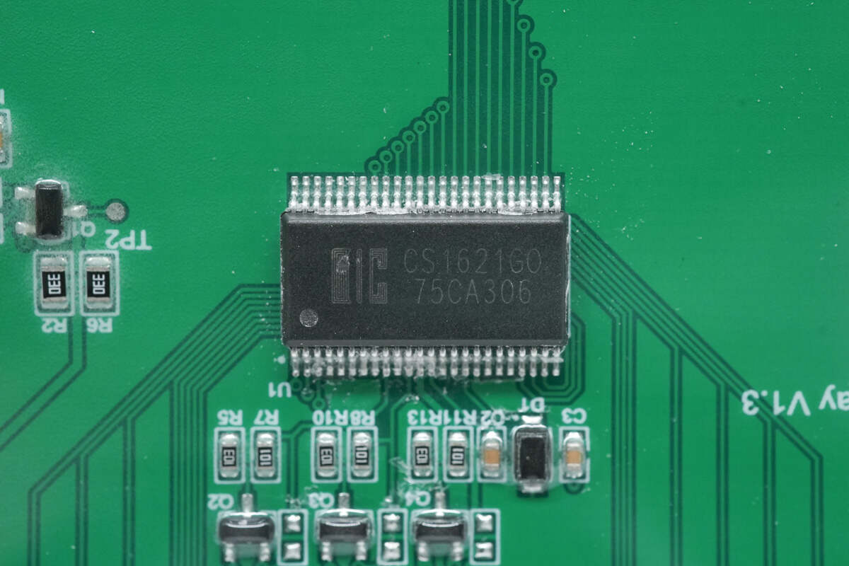
The driver chip is from i-Core. Model is CS1621.
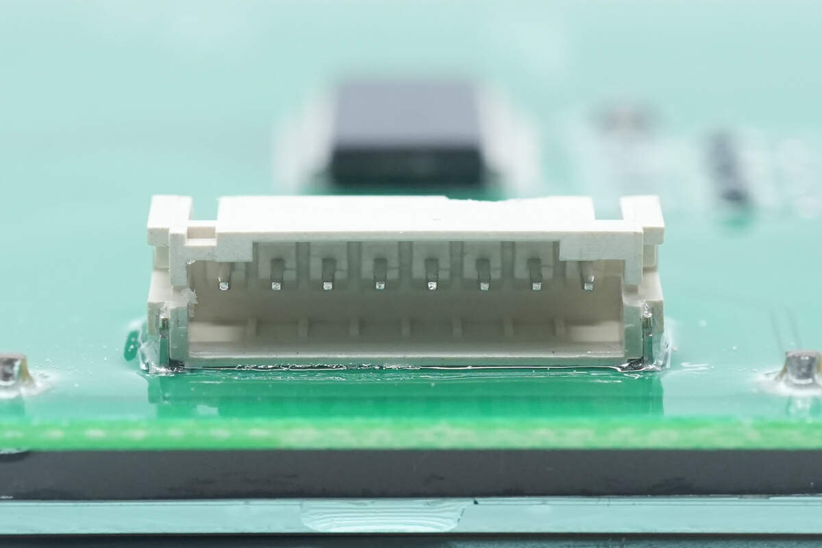
Here is the socket of the display.
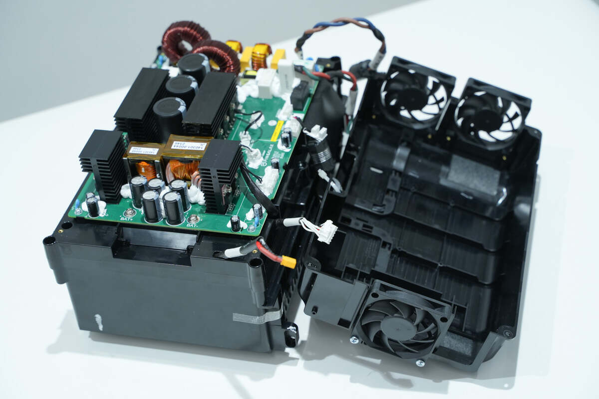
Unscrew the screws and open the bidirectional inverter module casing.
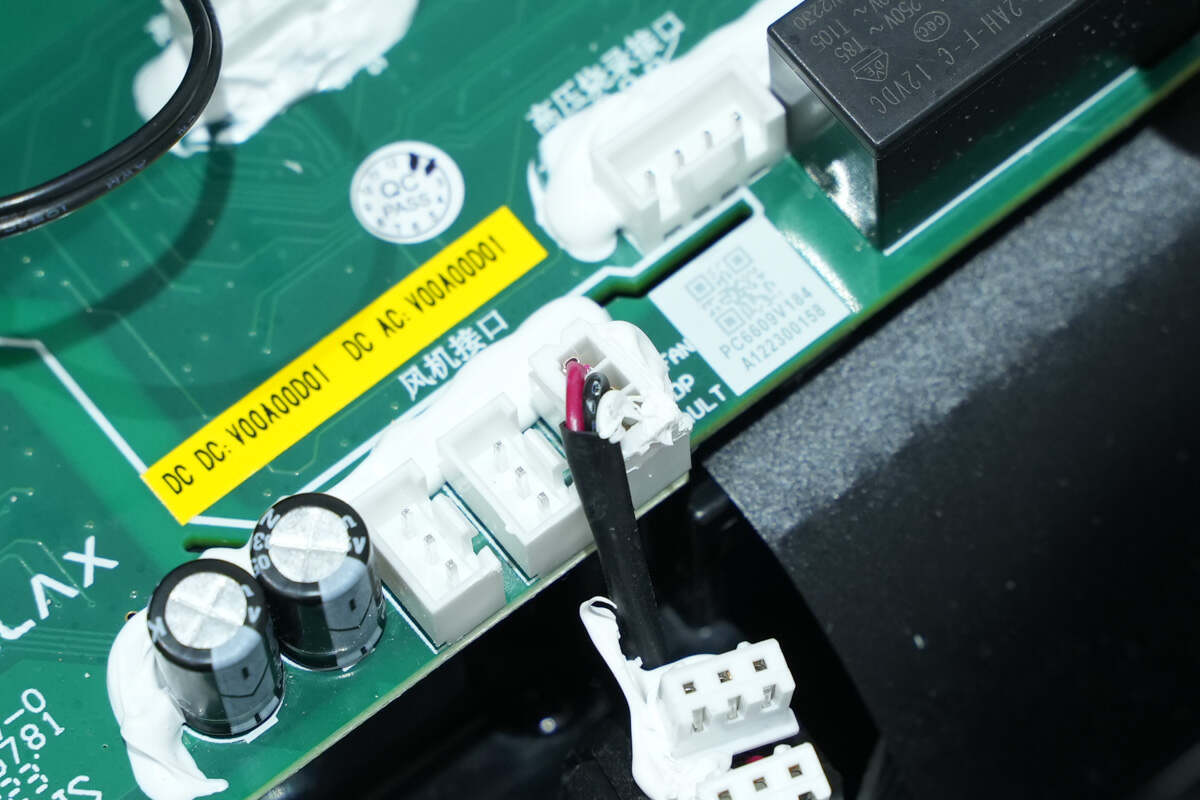
The fans are connected via these connectors.
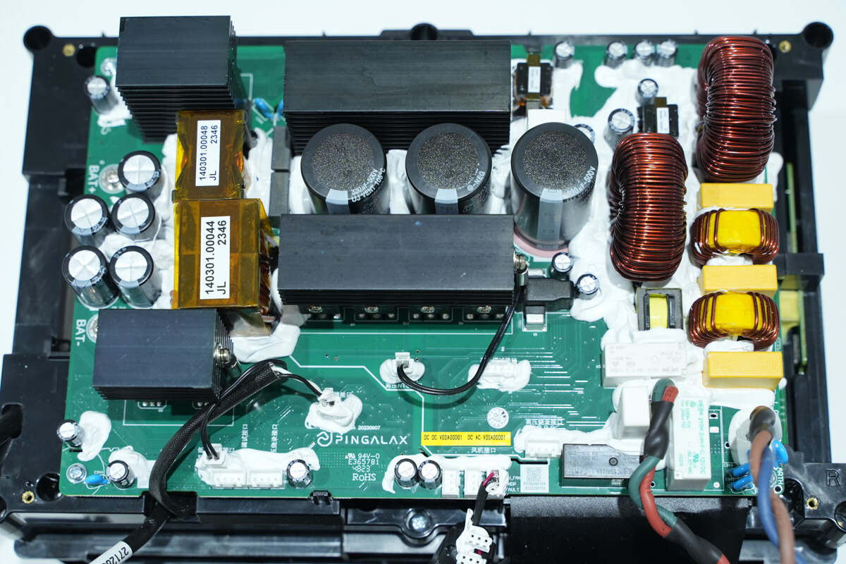
The PCB of the inverter module is fixed inside the casing with screws. The components are reinforced with potting compound.
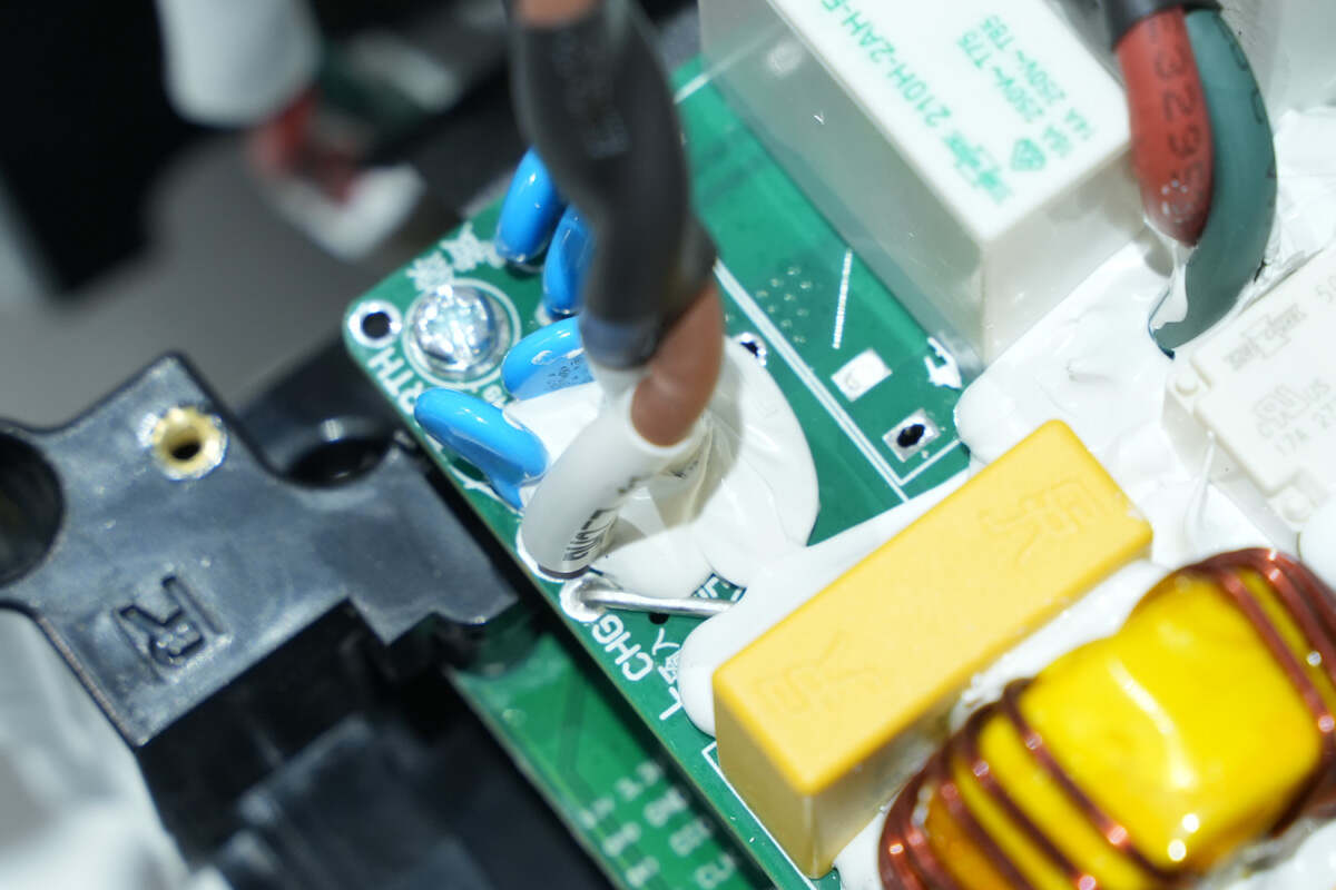
The AC input wires are connected by soldering.
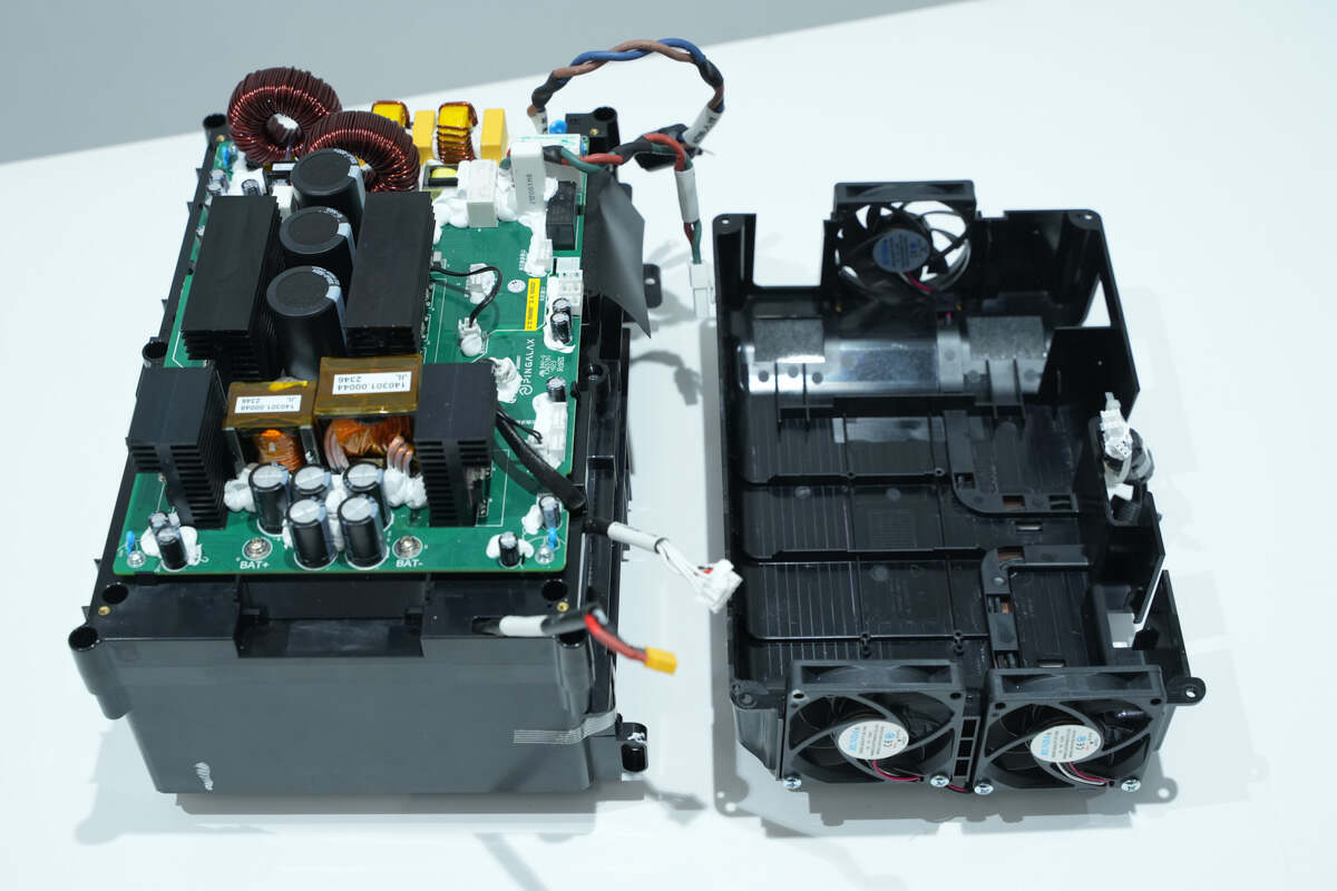
Disconnect the cooling fans from the PCBA module and separate the upper cover of the inverter module.
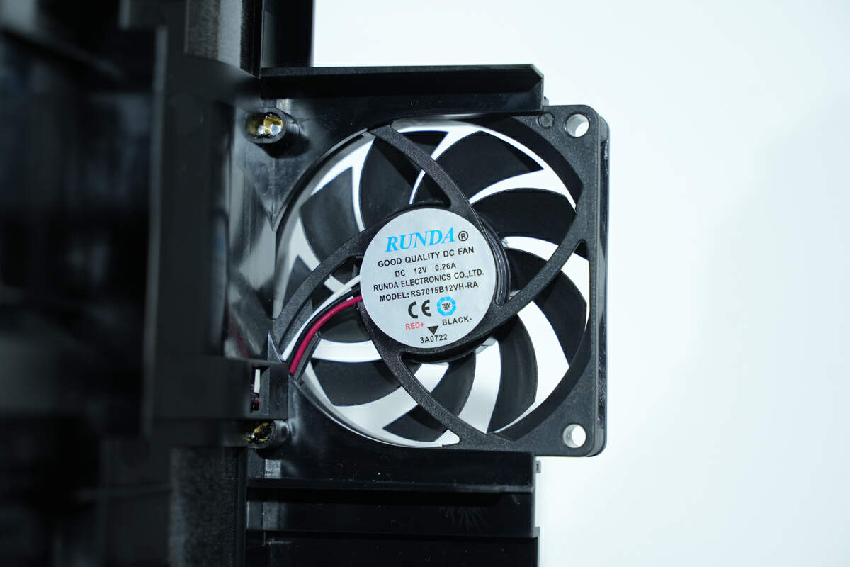
The fan is from RUNDA. Model is RS7015B12VH-RA. 12V 0.26A.
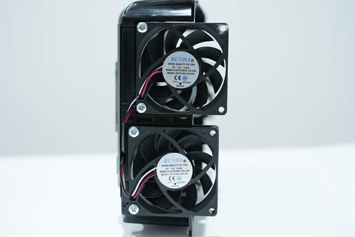
The two fans on the other side are the same as the previous one.
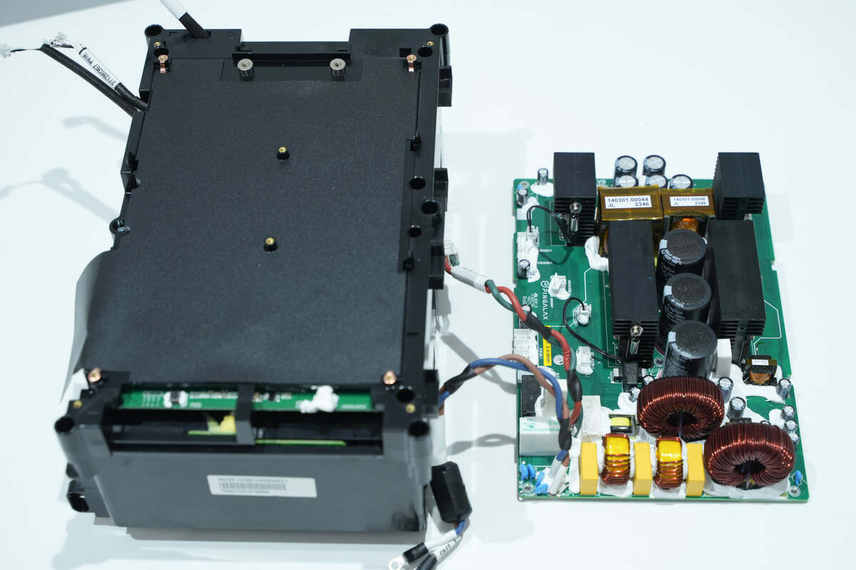
Unscrew the fixing screws and separate the battery pack and bidirectional inverter module.
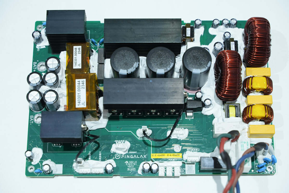
There are capacitors, MOSFET, transformer, filter inductor, safety X2 capacitor, common mode inductor, relay, and varistor on the front of the PCBA module.
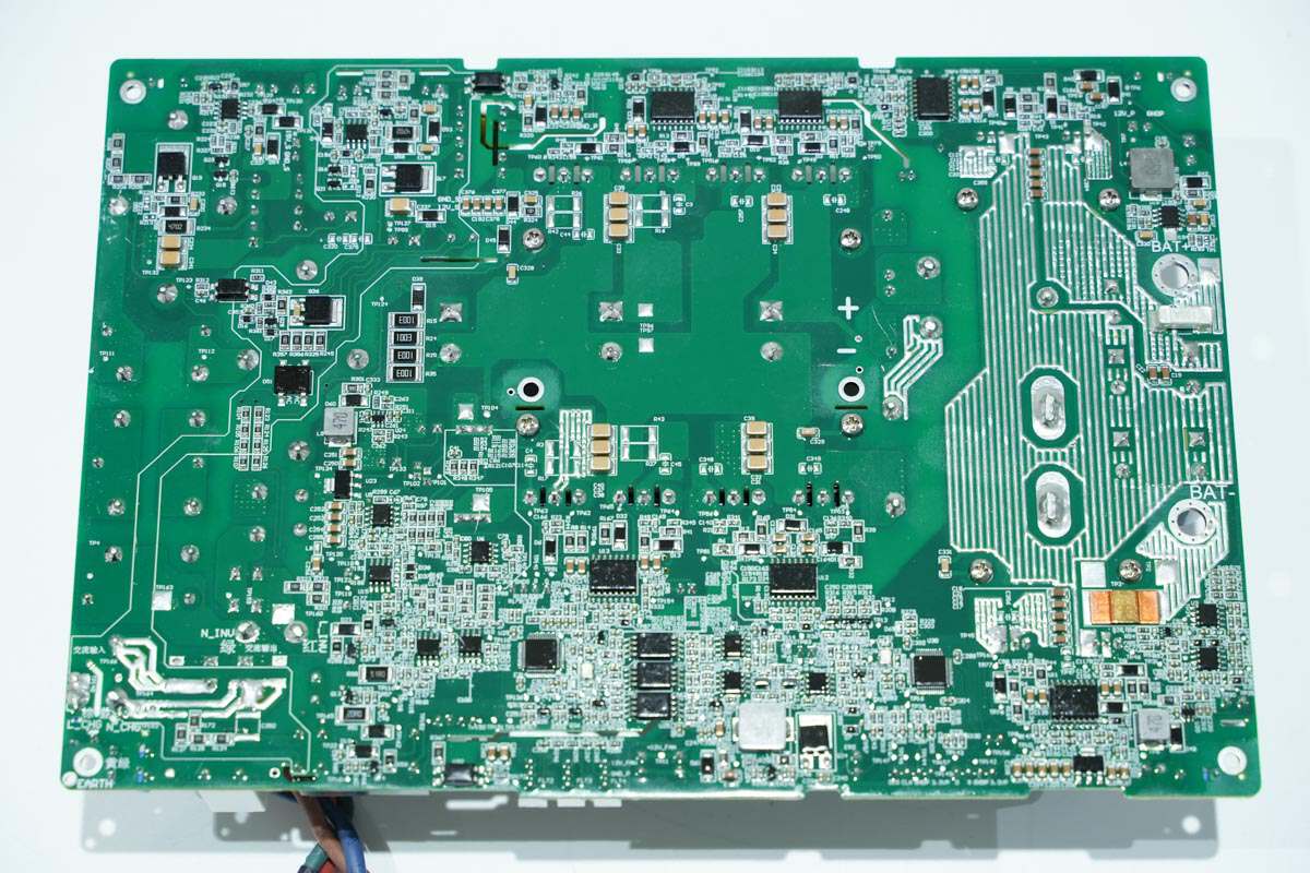
Two MCUs are on the back of the PCBA module for primary and secondary control respectively, and the MOSFETs corresponding to the primary and secondary sides are driven by isolated drivers.
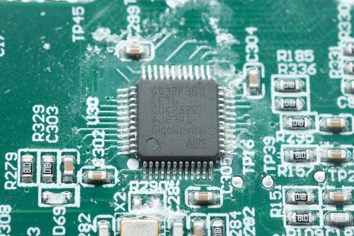
The MCU used for DC side control comes from GigaDevice. Its frequency can reach 120MHz. It has a built-in Cortex-M4 core with 512KB FLASH and 64KB SRAM. Model is GD32F303CET6.
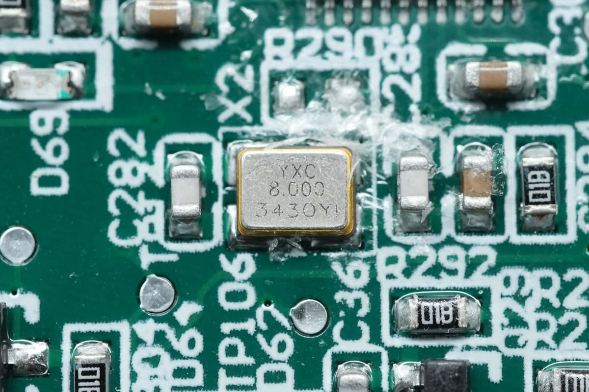
There is the 8.000MHz crystal oscillator.
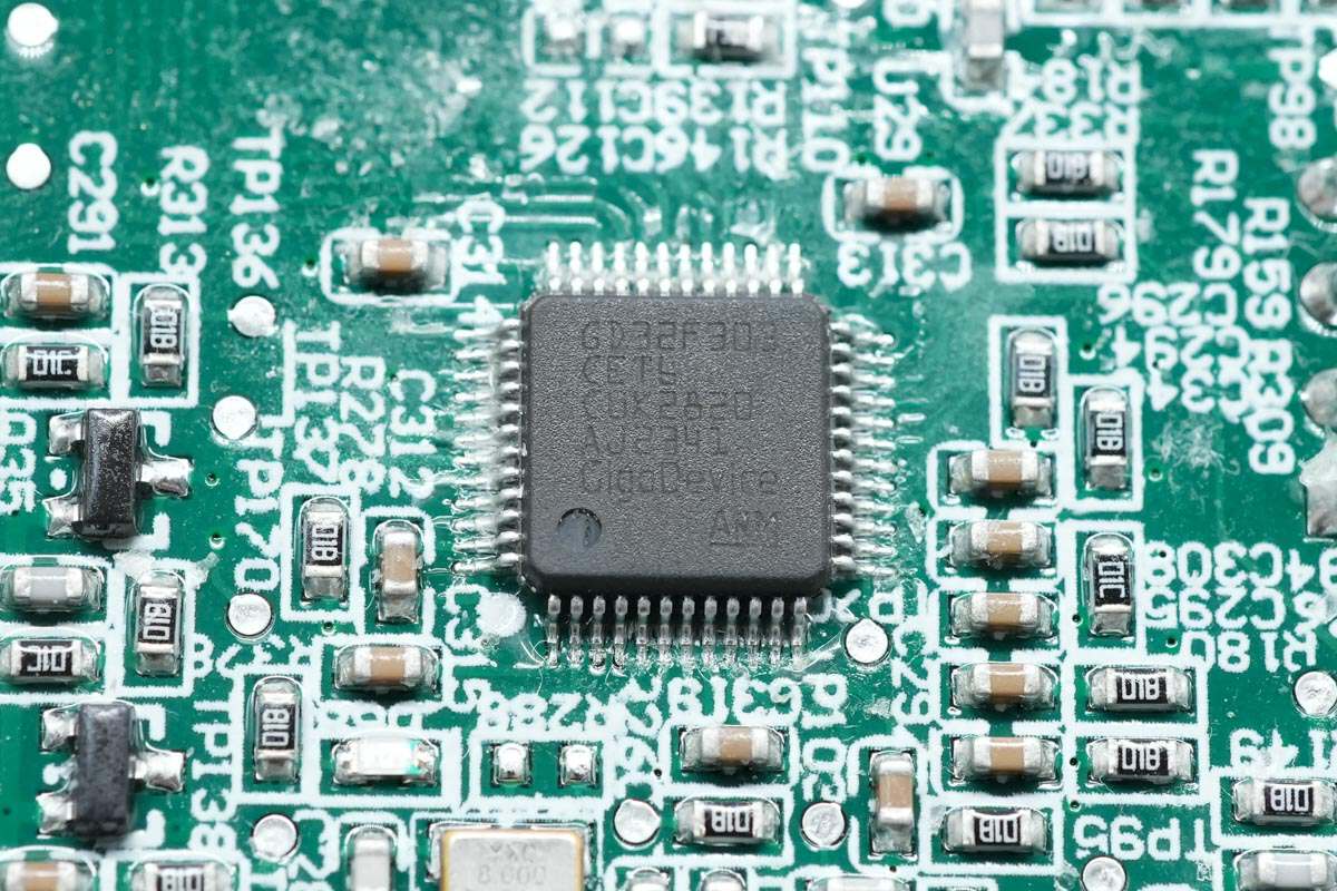
The MCU for AC control is the same as the previous one.
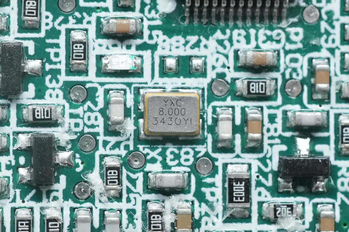
There is the 8.000MHz crystal oscillator.
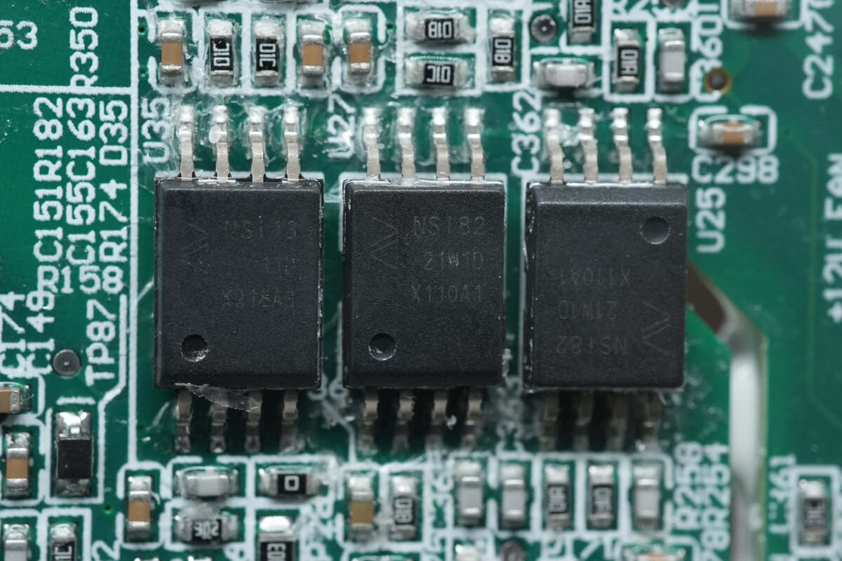
The three digital isolators used between the two MCUs are from NOVOSENSE. Model is NSi8221.
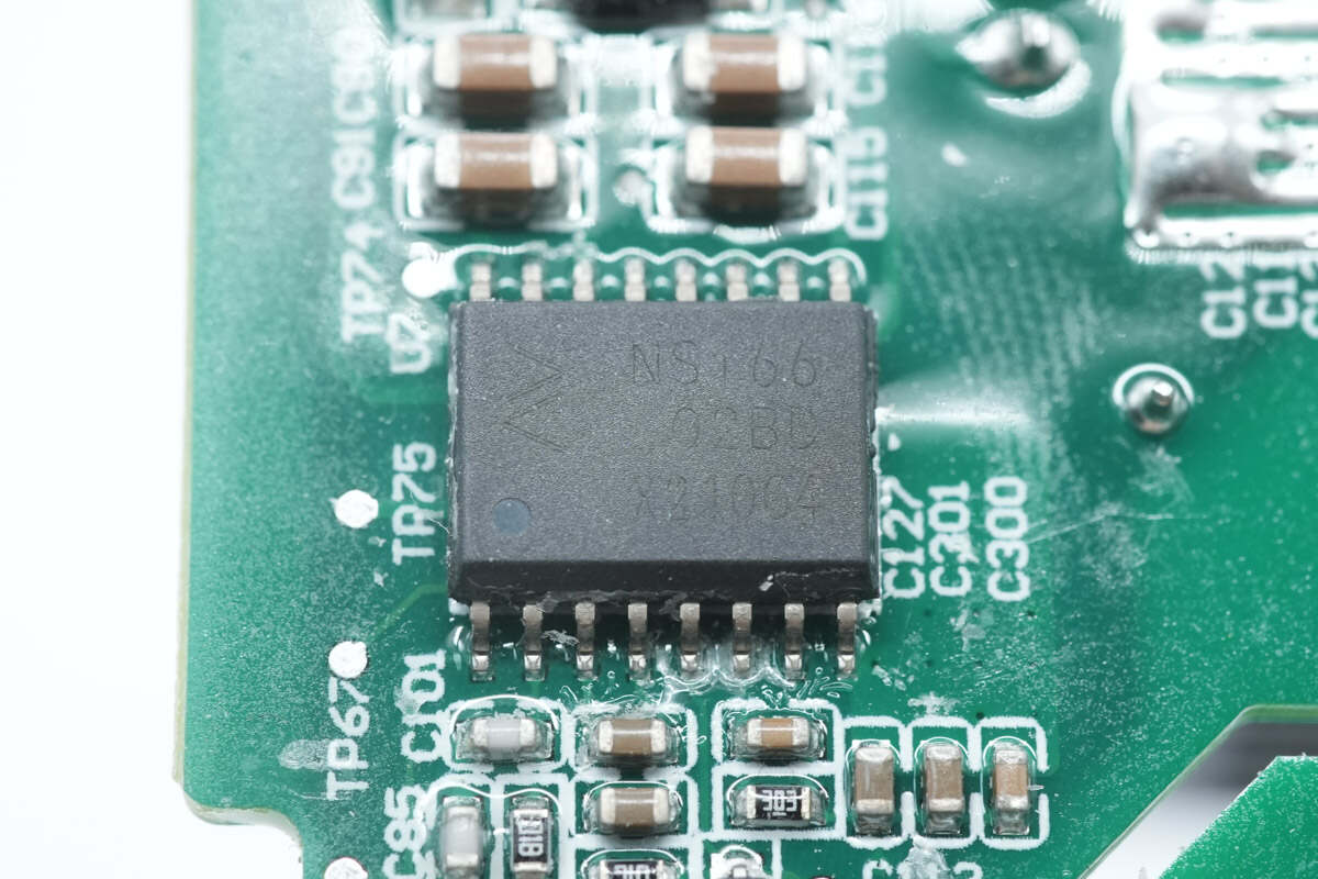
The six isolation drivers corresponding to the MOSFETs come from NOVOSENSE. Model is NSi6602BD.
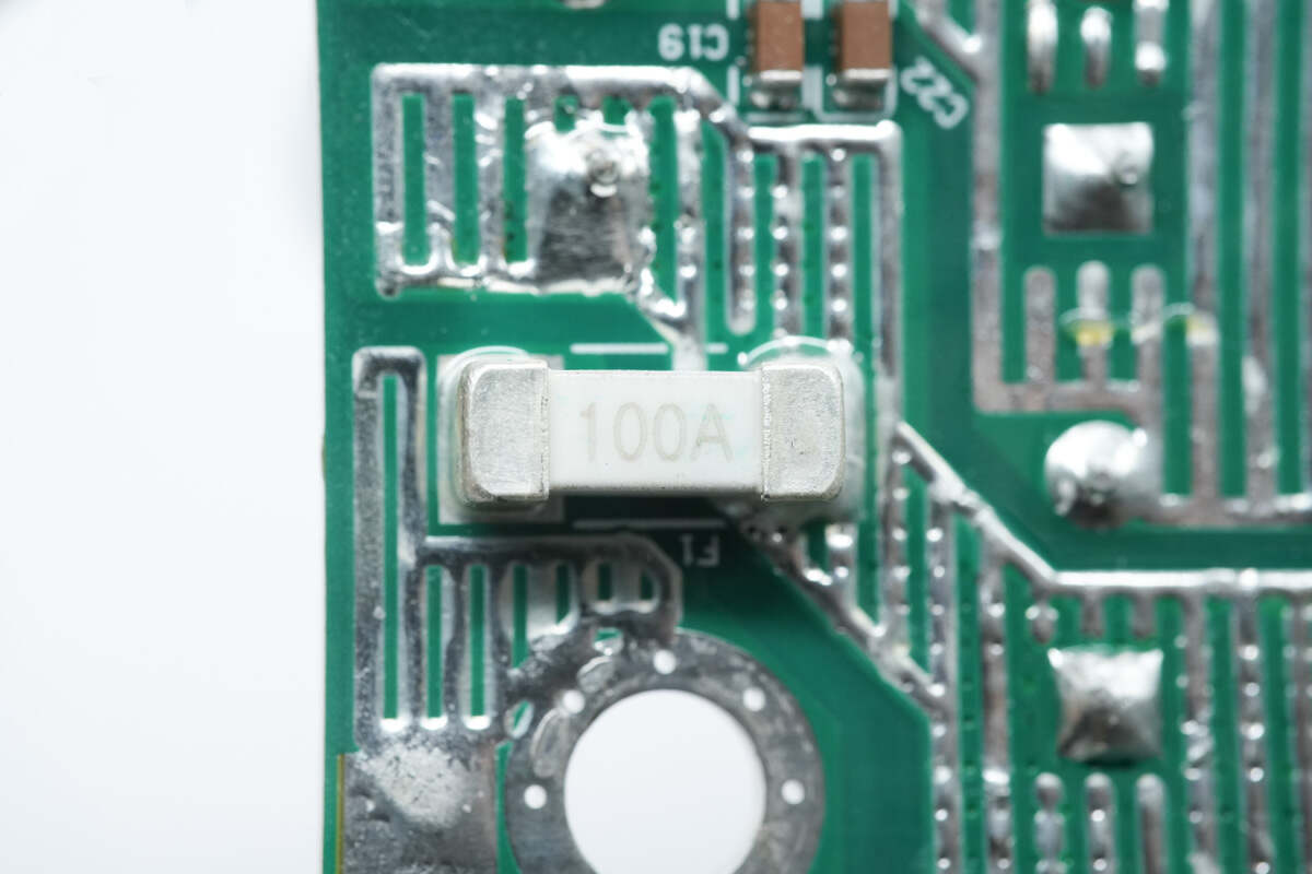
This is the fuse of the DC side. 100A.
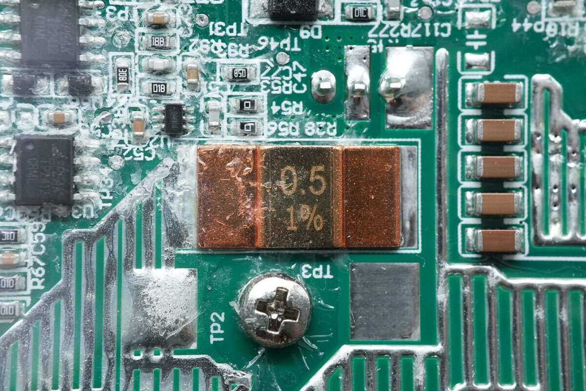
The sampling resistor is used to detect DC current. 0.5mΩ.
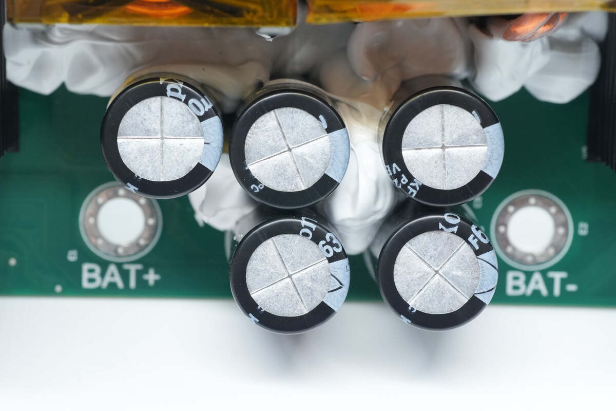
Here are the five electrolytic capacitors on the DC input.
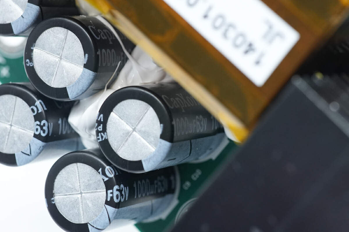
These five electrolytic capacitors for input filtering from CapXon are connected in parallel. 1000μF 63V.
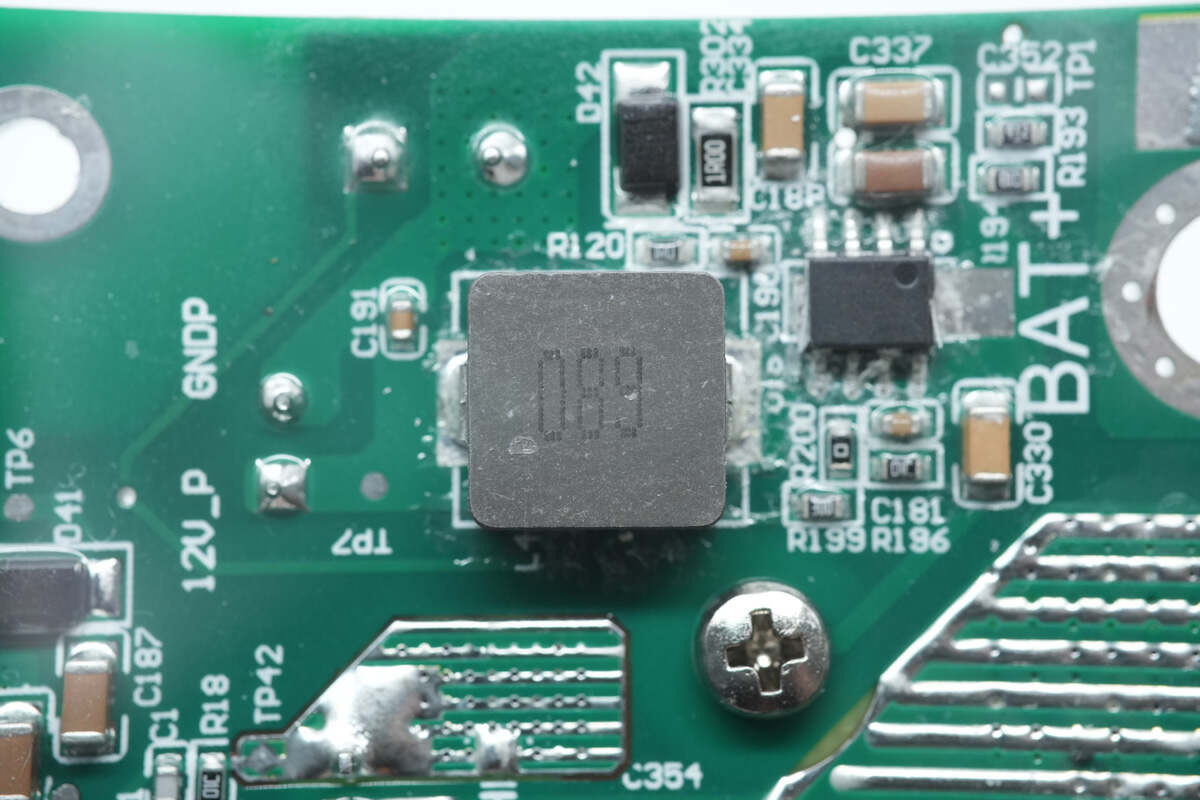
There is buck circuit at the input end.
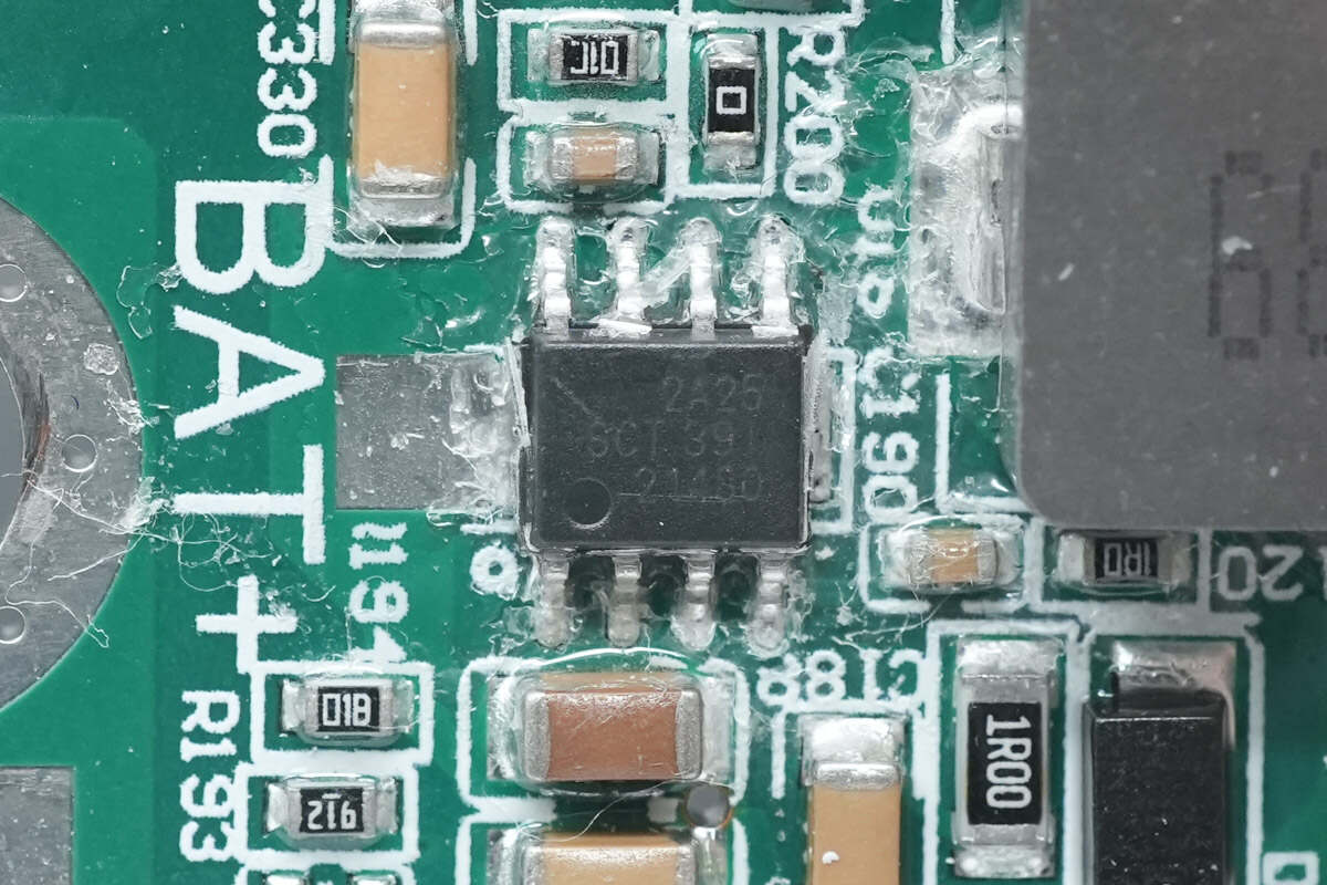
The buck chip is from Silicon. It is used to power the drive. Model is SCT2A25.
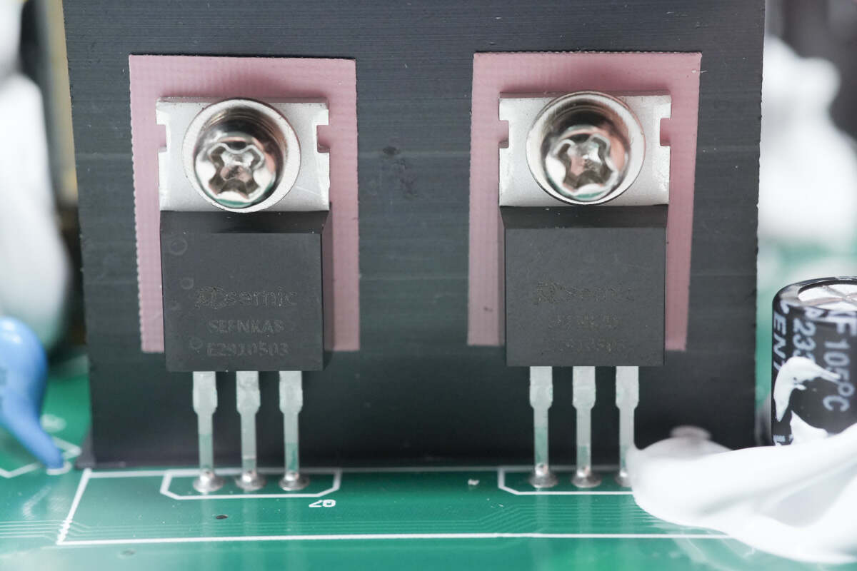
These two primary MOSFETs are from PCsemic. There are insulating pads between them and the heat sink.
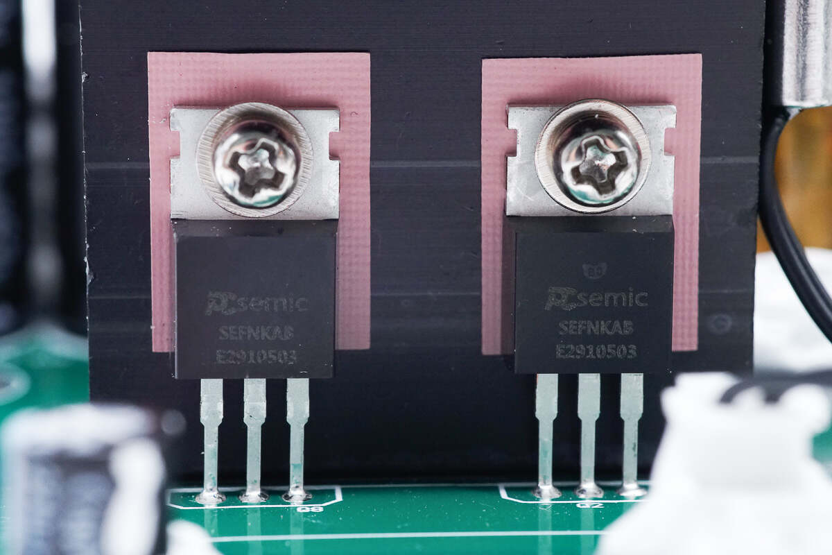
The other two MOSFETs are the same as the first two.
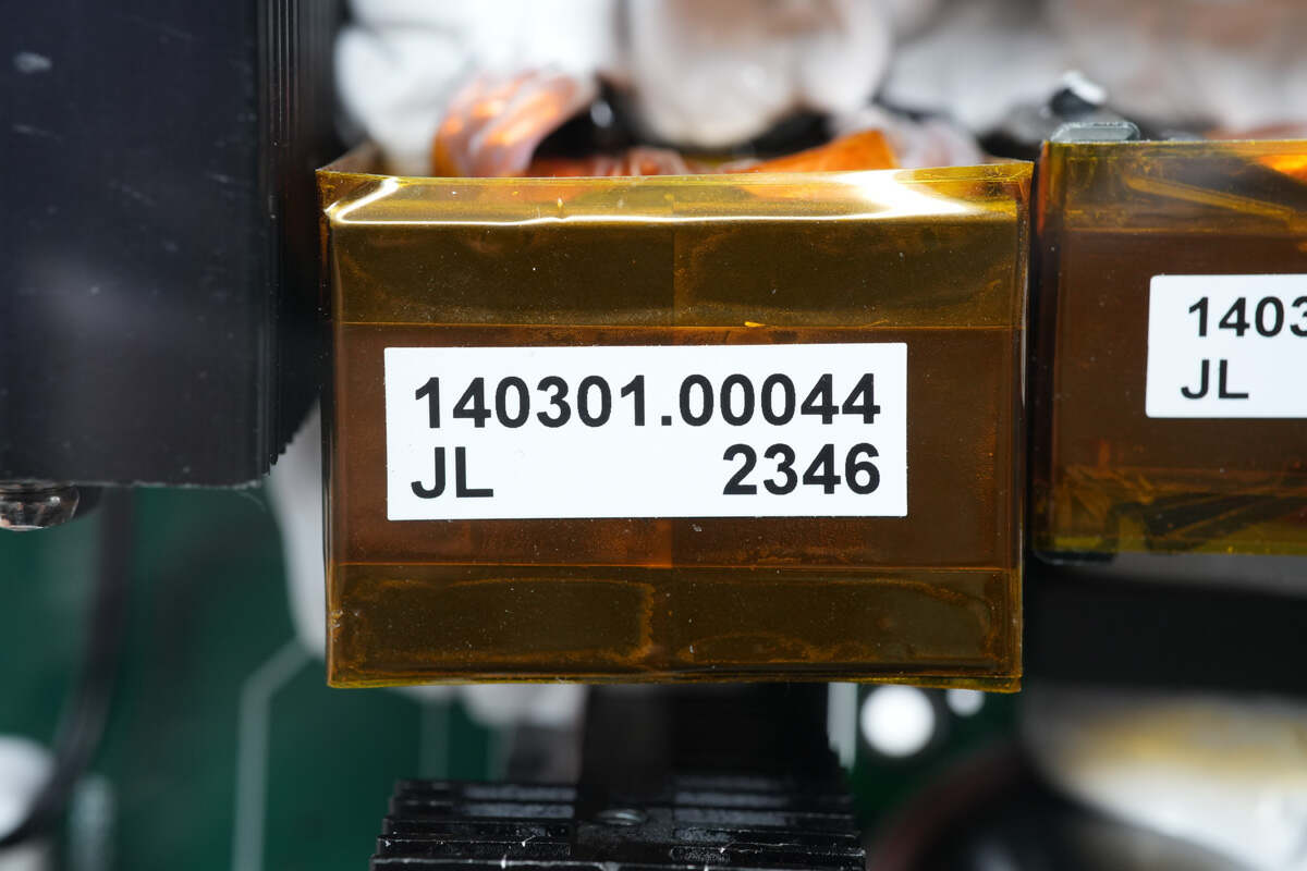
The magnetic core of the transformer is insulated by tape.
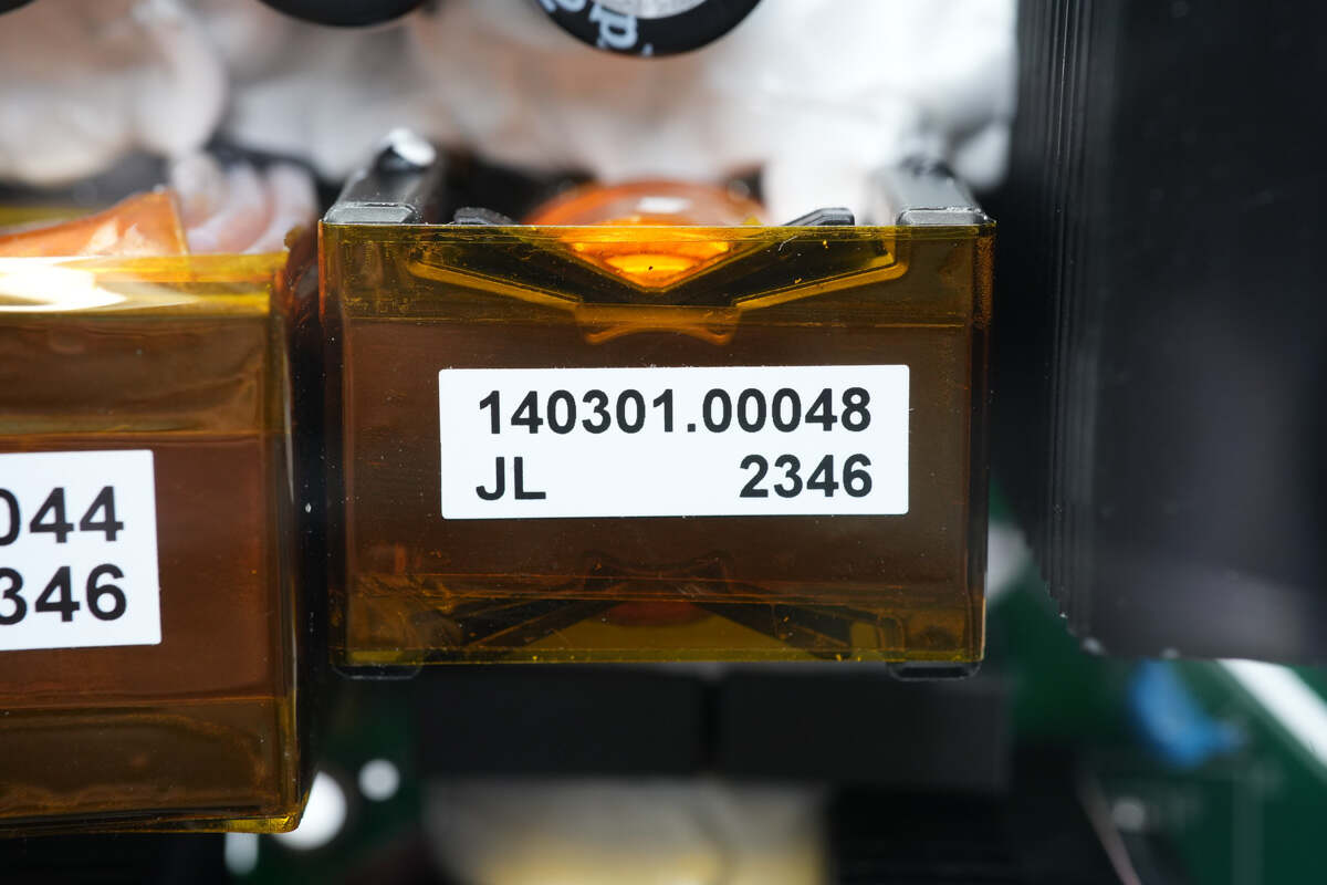
The magnetic core of the resonant inductor is insulated by tape.
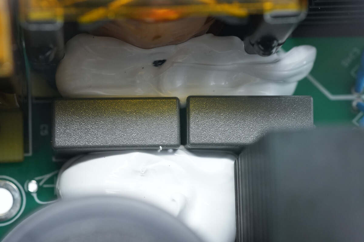
These two resonant capacitors are reinforced with glue.
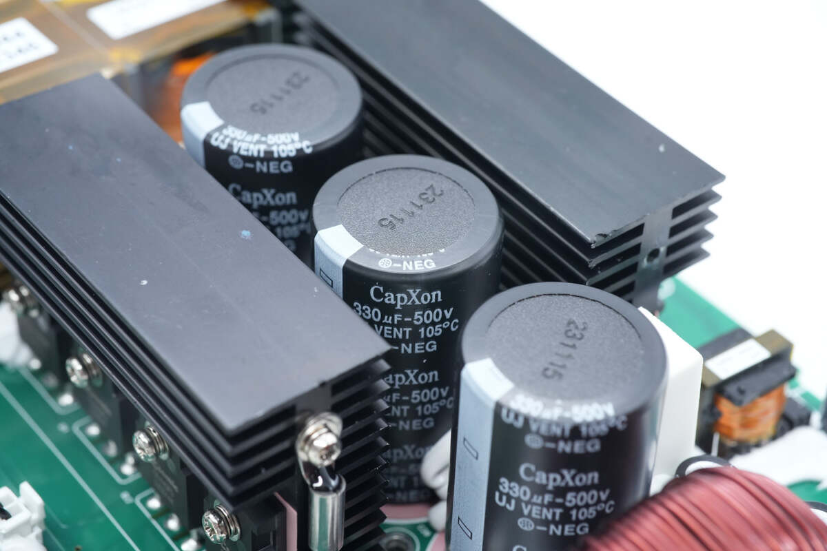
The filter capacitors are from CapXon. There are heat sinks on both sides of the filter capacitors, and the heat sink is also equipped with a thermistor for temperature detection. 330μF 500V.
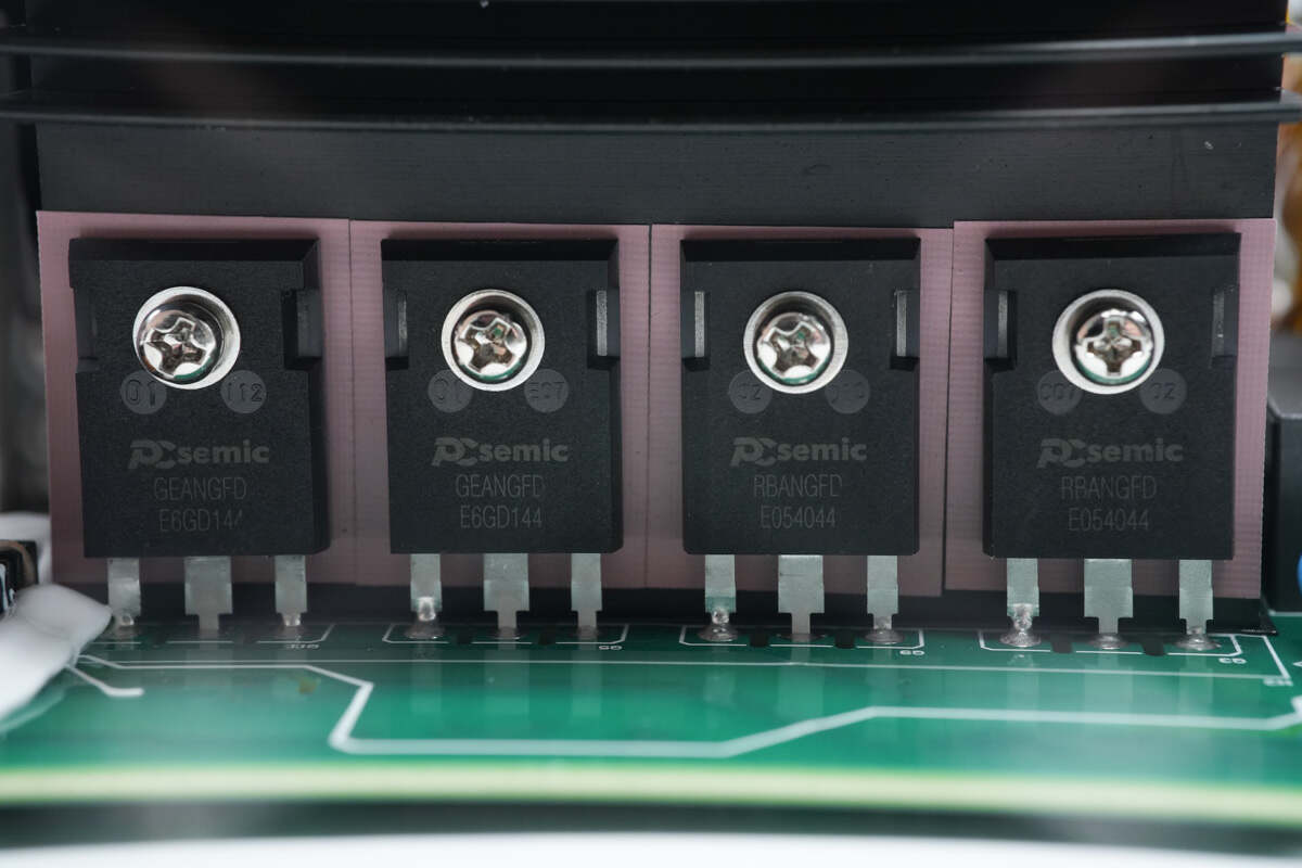
Four MOSFETs are fixed on the heat sink.
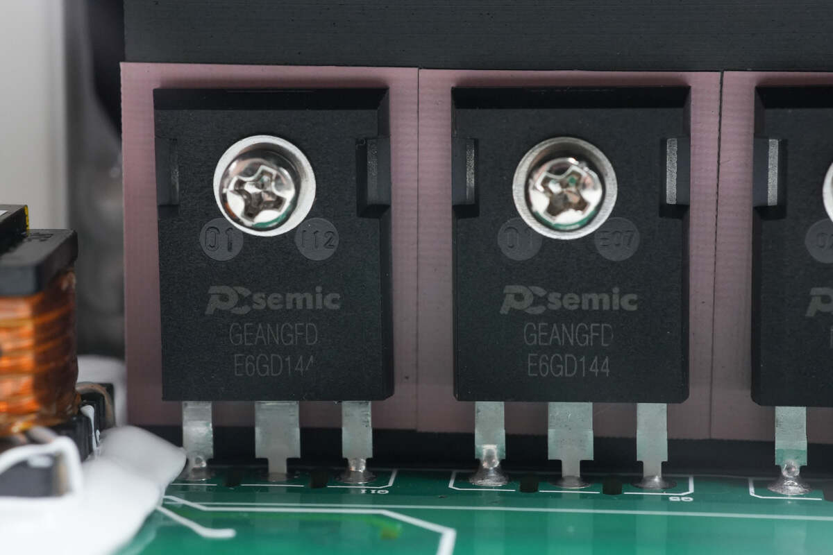
The MOSFET is from PCsemic. Two on the left are marked with GEANGFD.
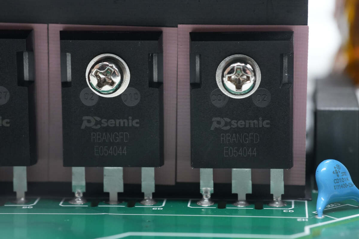
The two on the right are printed with RBANGFD.
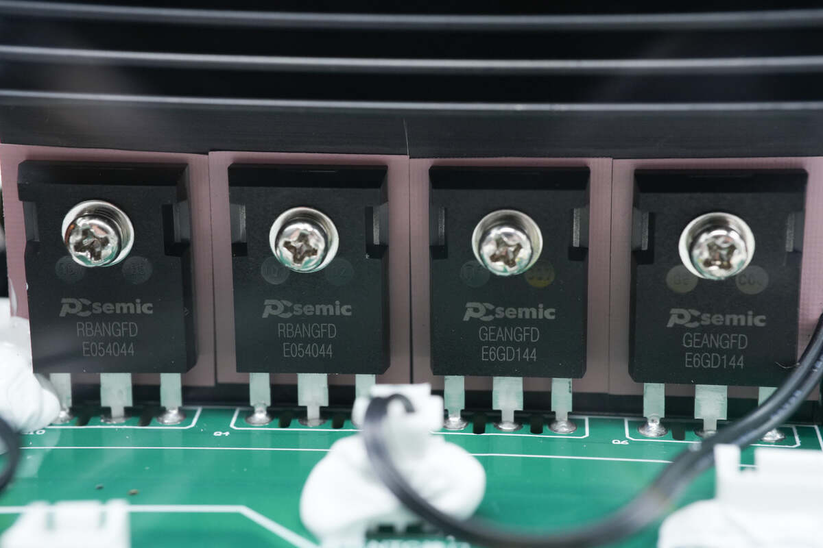
There are also four MOSFETs on the other heat sink.
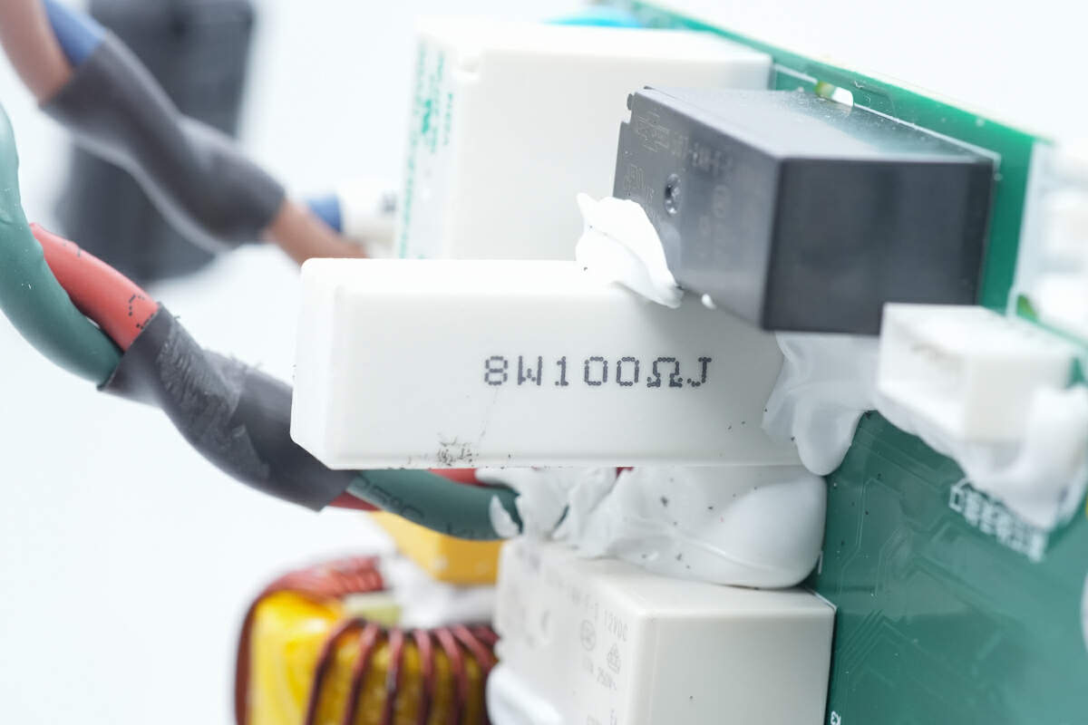
This is the cement resistor. 100Ω.
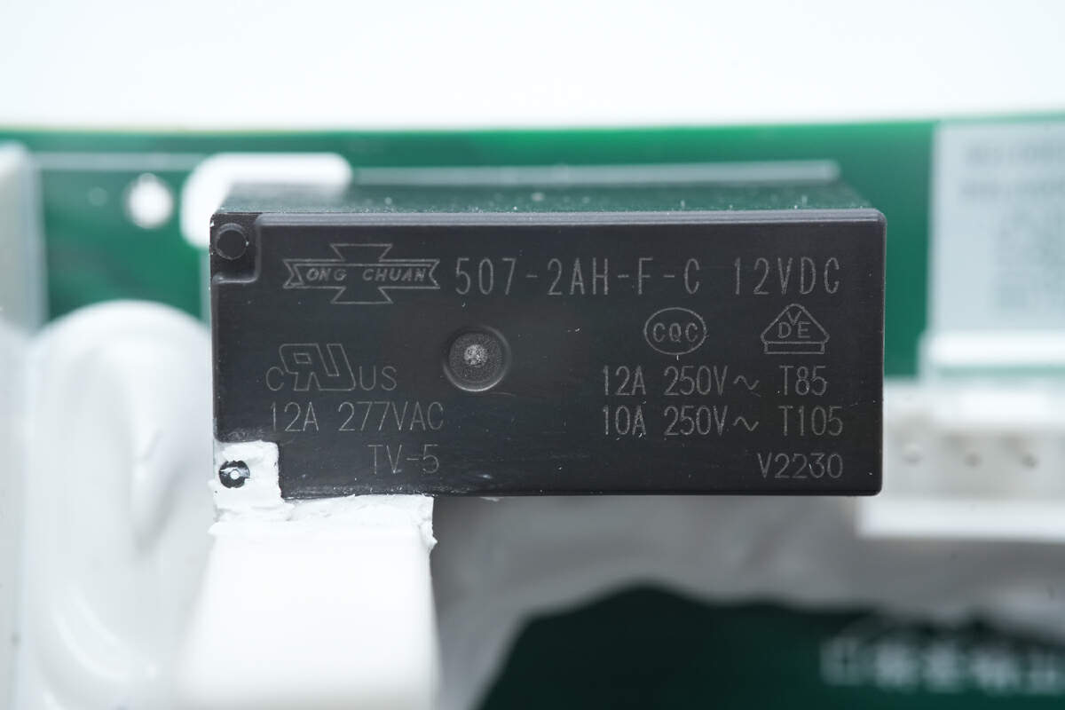
The relay is from SongChuan. The contact capacity is 12A and the coil voltage is 12V. Model is 507-2AH-F-C.
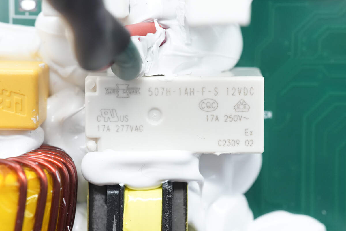
The relay is from SongChuan. The contact capacity is 17A and the coil voltage is 12V. Model is 507H-1AH-F-S.
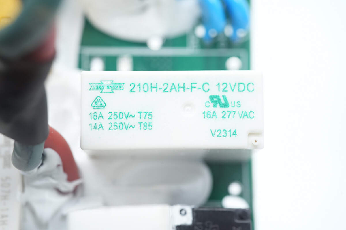
This relay is also from SongChuan. The contact capacity is 16A and the coil voltage is 12V. Model is 210H-2AH-F-C.
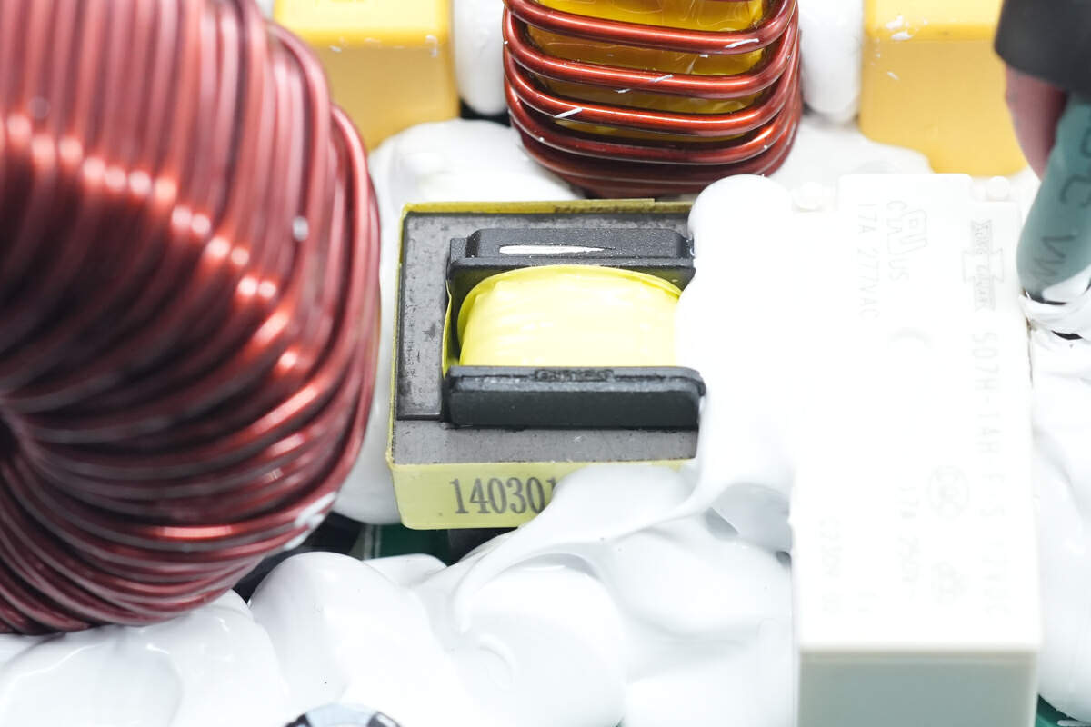
There is the current transformer.
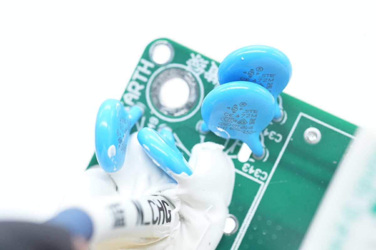
The blue Y capacitor is from STE.
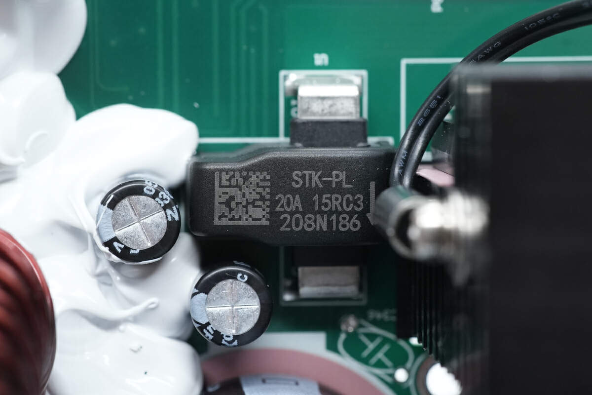
The current sensor is from SINOMAGS. Model is STK-PL. 20A.
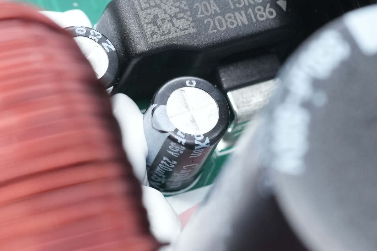
The specification of the filter capacitor is 220μF 35V.
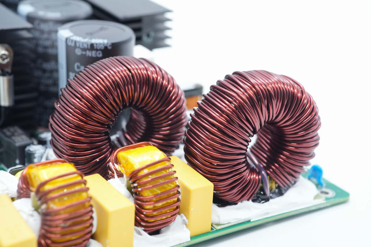
There are two inductors.
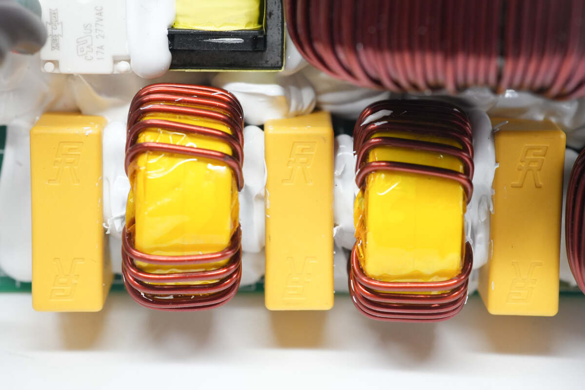
There are safety X2 capacitors and common mode chokes.
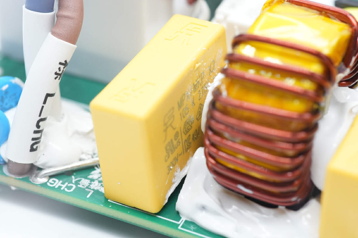
The safety X2 capacitor is from SINCERITY. 1μF.
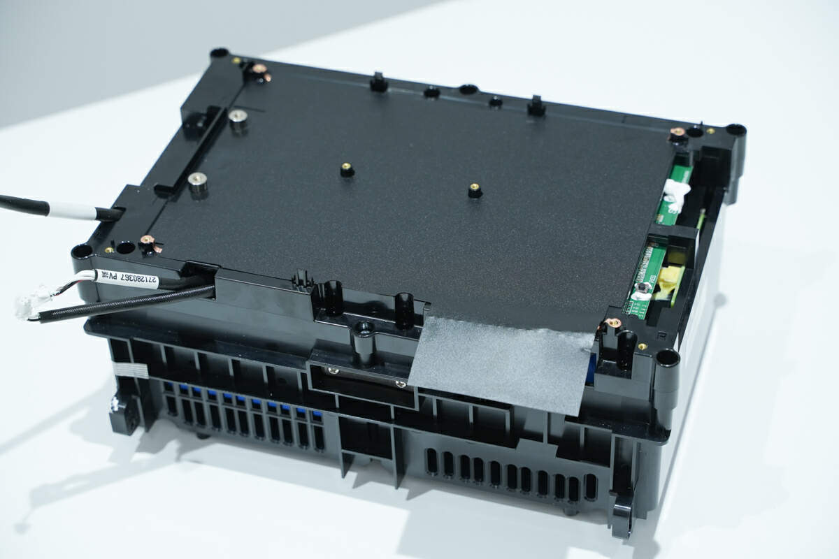
The battery pack and the bidirectional inverter module are insulated by mylar sheets. The positive and negative poles are connected to the PCB of the bidirectional inverter module through the binding posts of the battery pack.

Unscrew the screws and take apart the battery pack casing. The battery protection PCB is fixed on the upper cover.
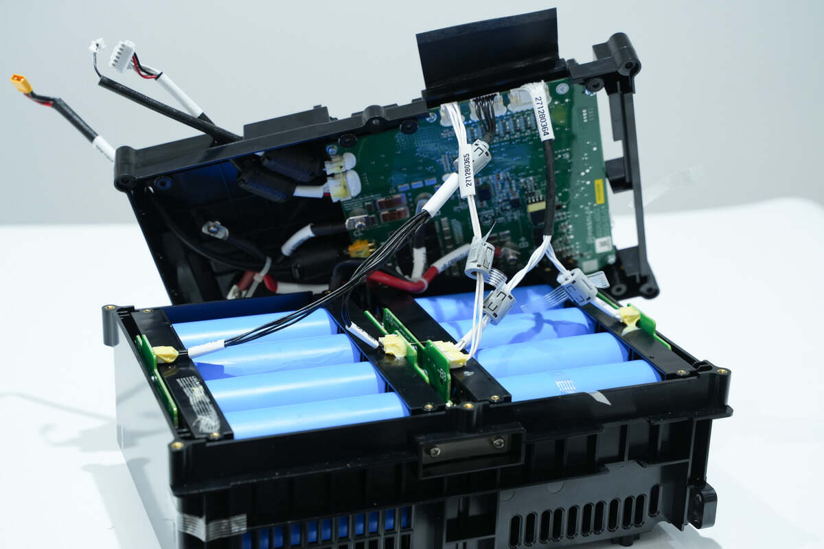
The battery pack and the PCB are connected through wires.
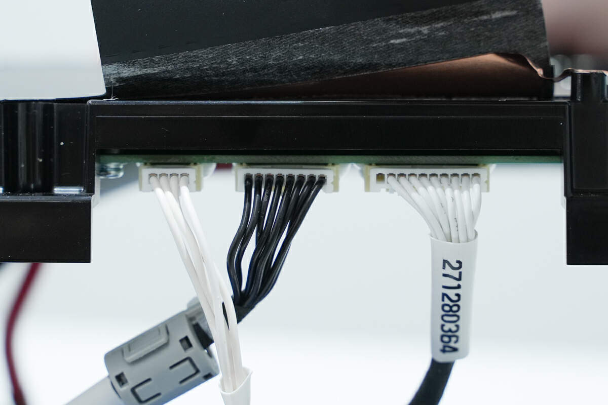
There are the wires.
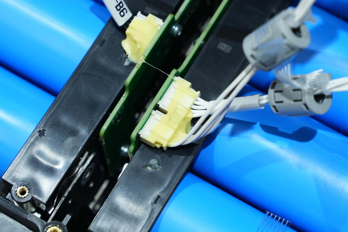
There are connectors on the PCB on the side of the battery pack.
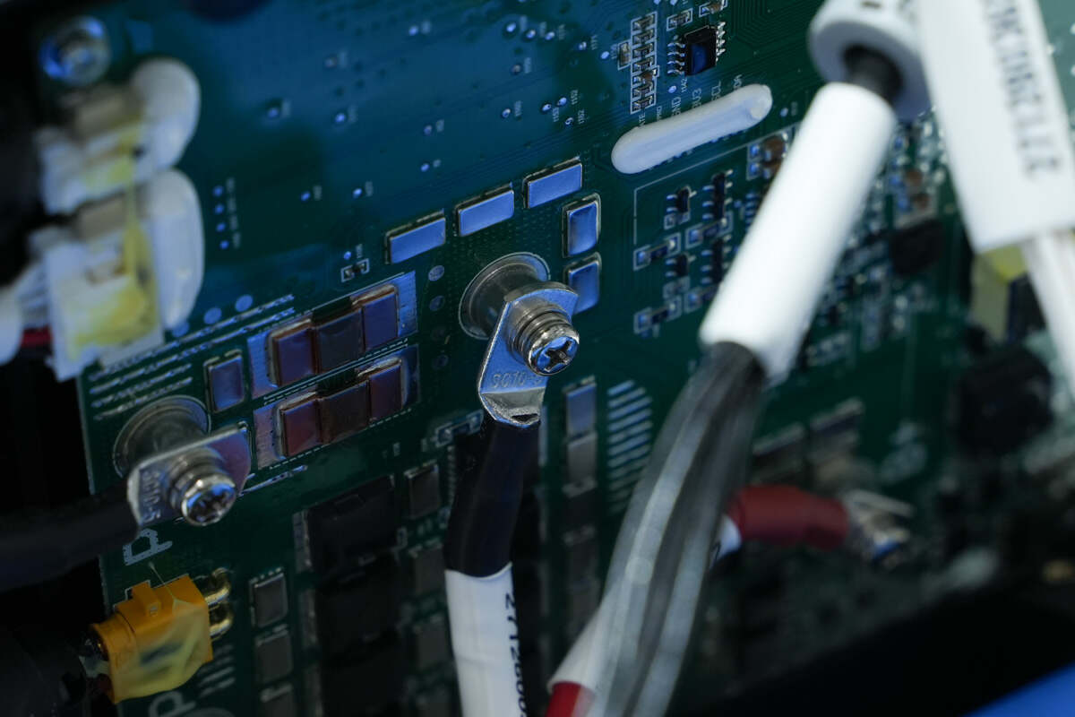
The positive and negative poles of the battery pack are connected through wires and binding posts.
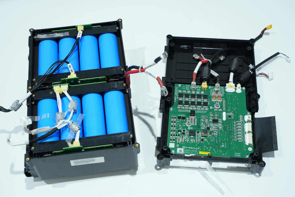
Disconnect the battery pack and battery protection PCB.
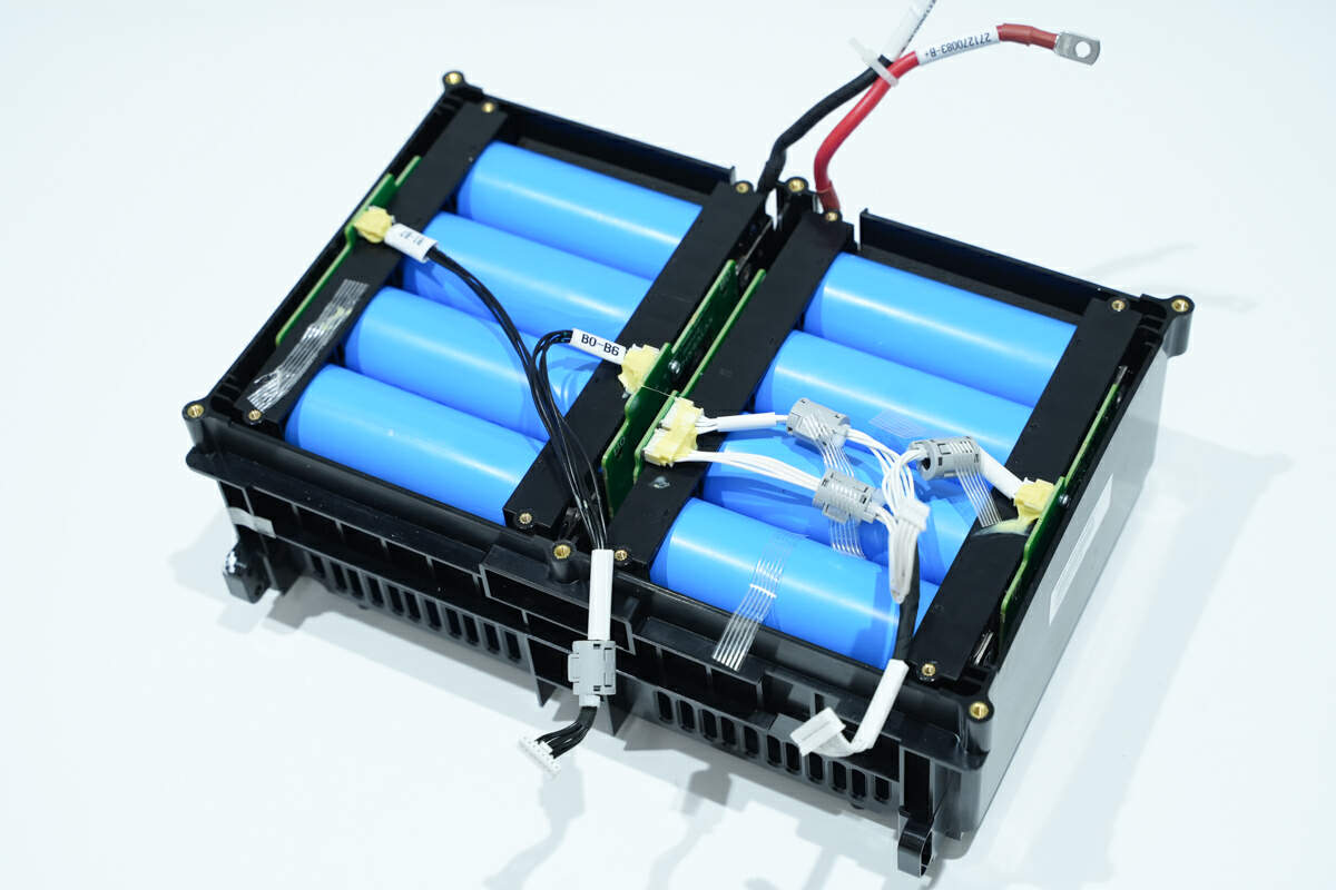
The positive and negative poles of the battery pack are connected to the PCB via silicone wires.
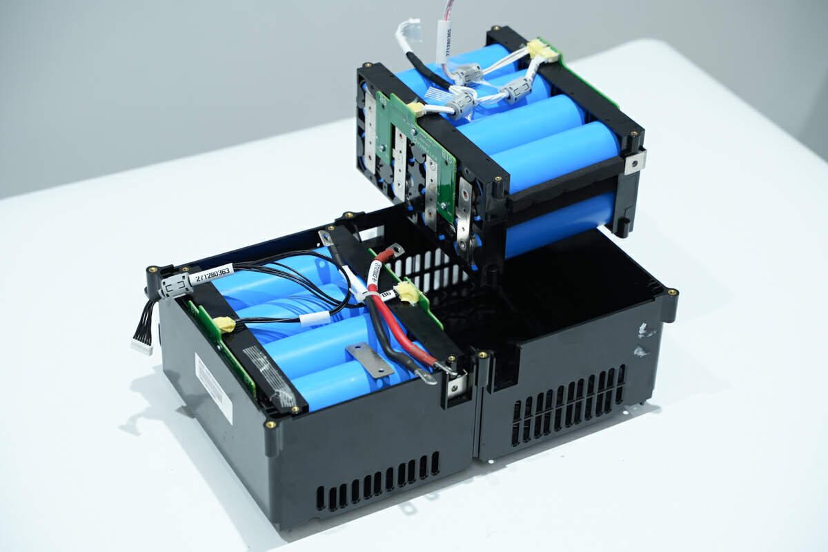
The batteries are fixed with an insulating frame. Eight batteries make up a set, and there are two sets of batteries in series.
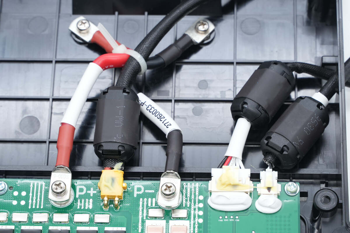
The battery packs are connected through copper sheets.
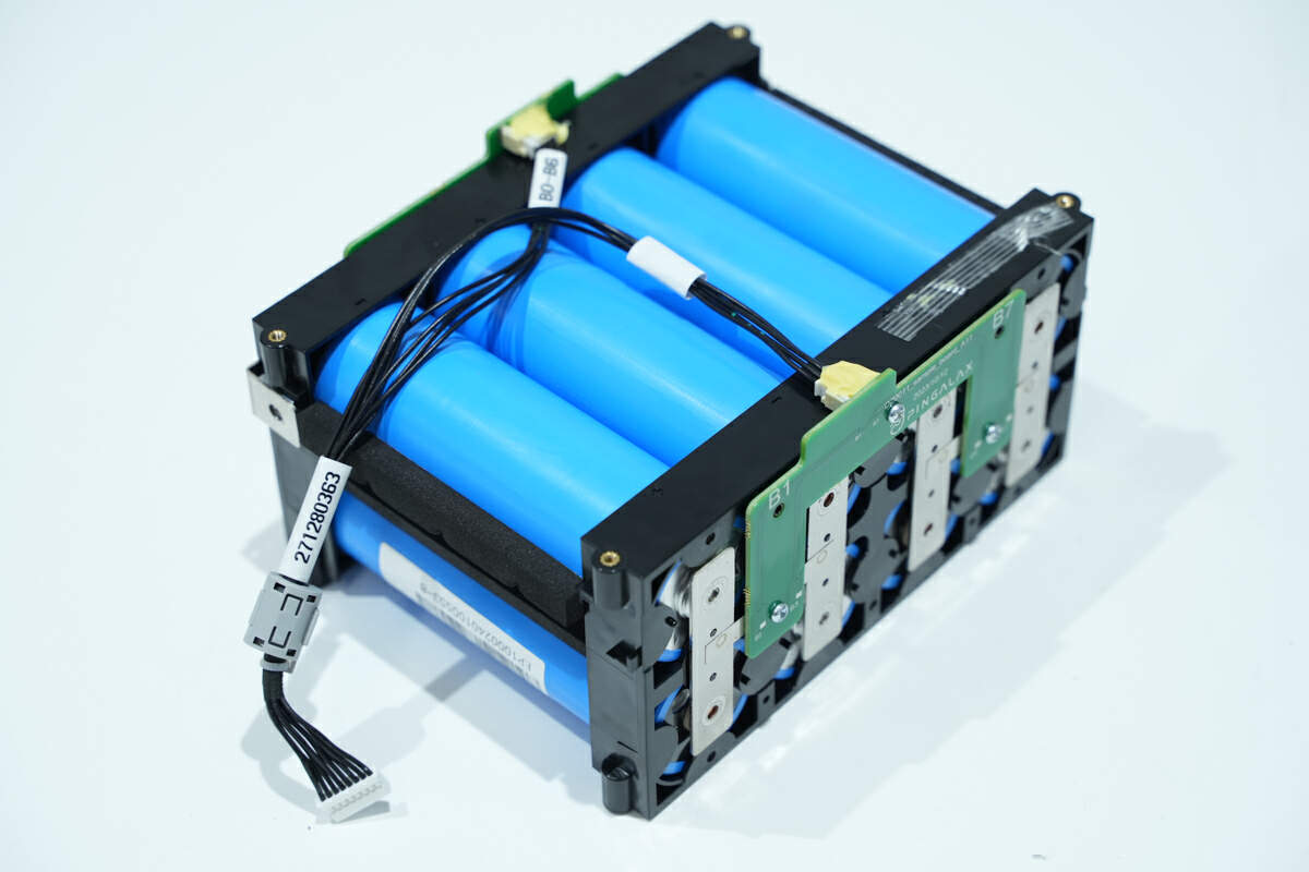
There are PCBs on both sides of the battery pack for voltage detection.
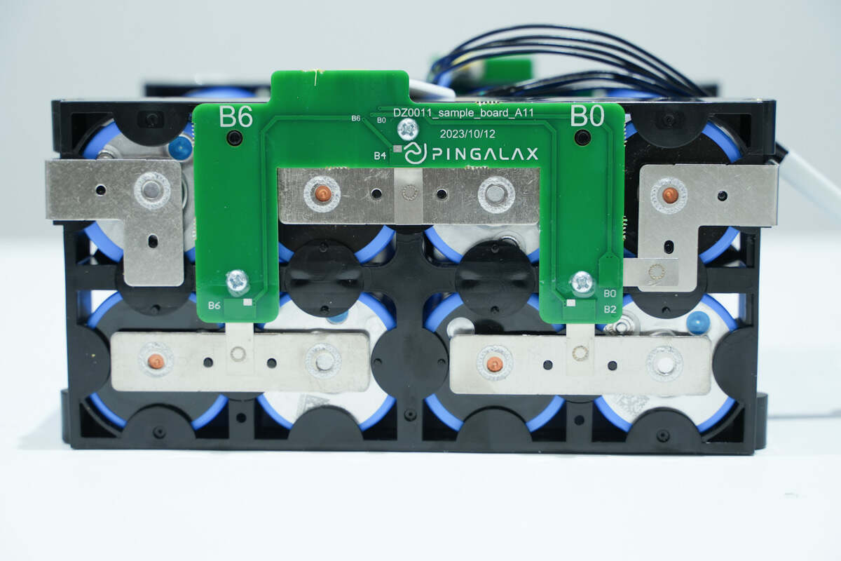
The PCB is connected to the voltage sampling point of the battery pack.
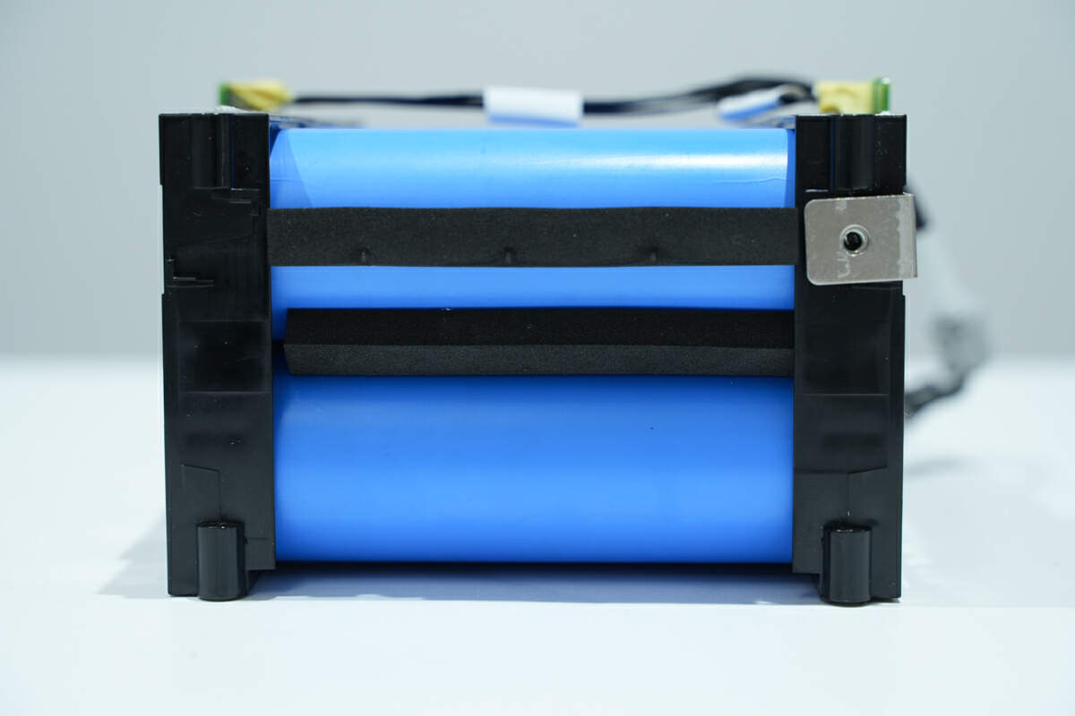
The batteries are held in plastic frames.
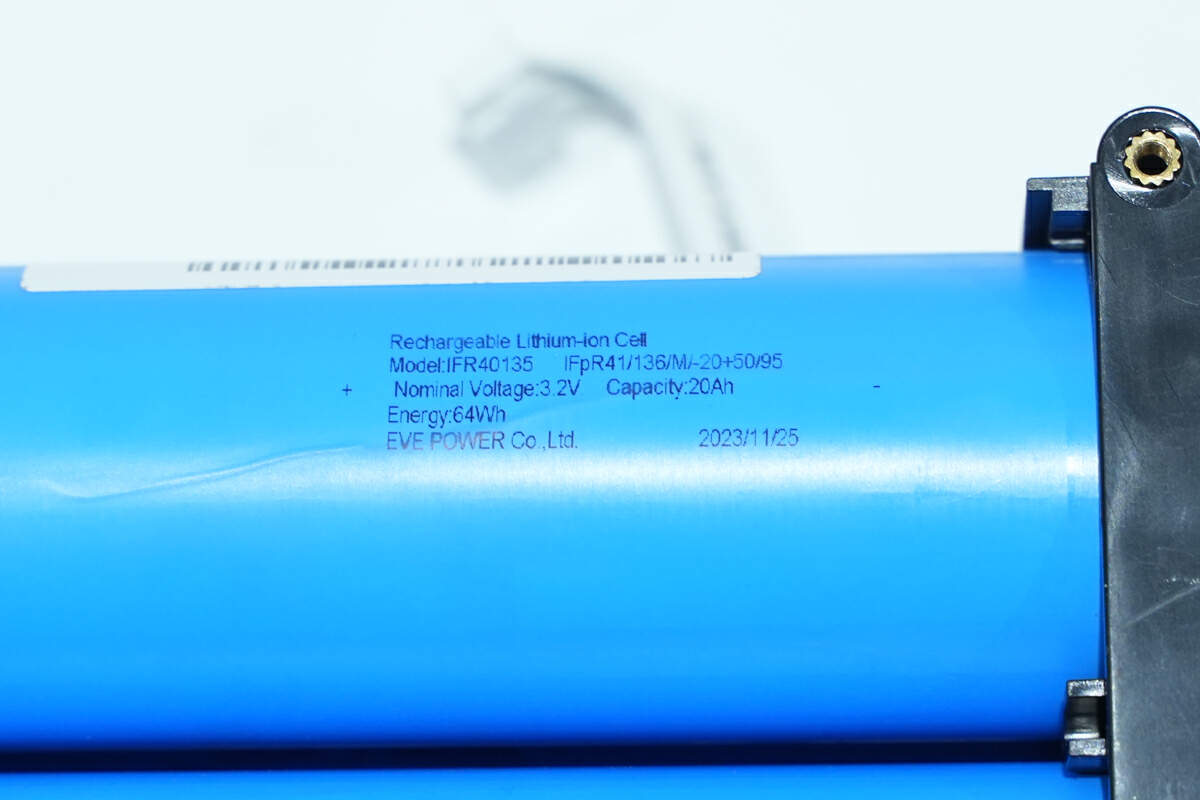
The battery is from EVE. Model is IFR40135. 20Ah 3.2V 64Wh.
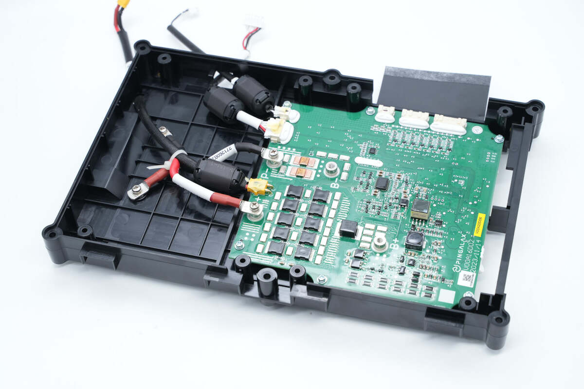
The battery protection PCB is fixed inside the frame with screws.

The output side of the protection PCB is connected through binding posts and sockets.
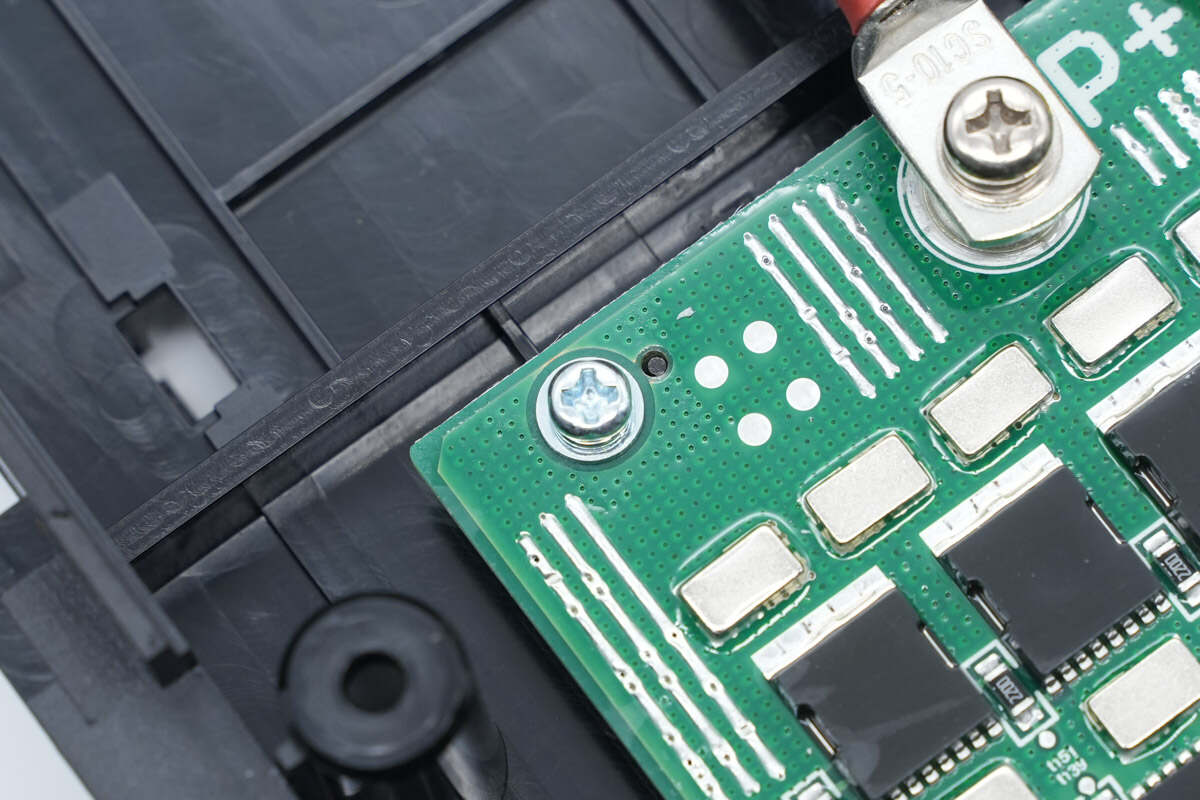
The protective PCB is fixed inside the case with screws.
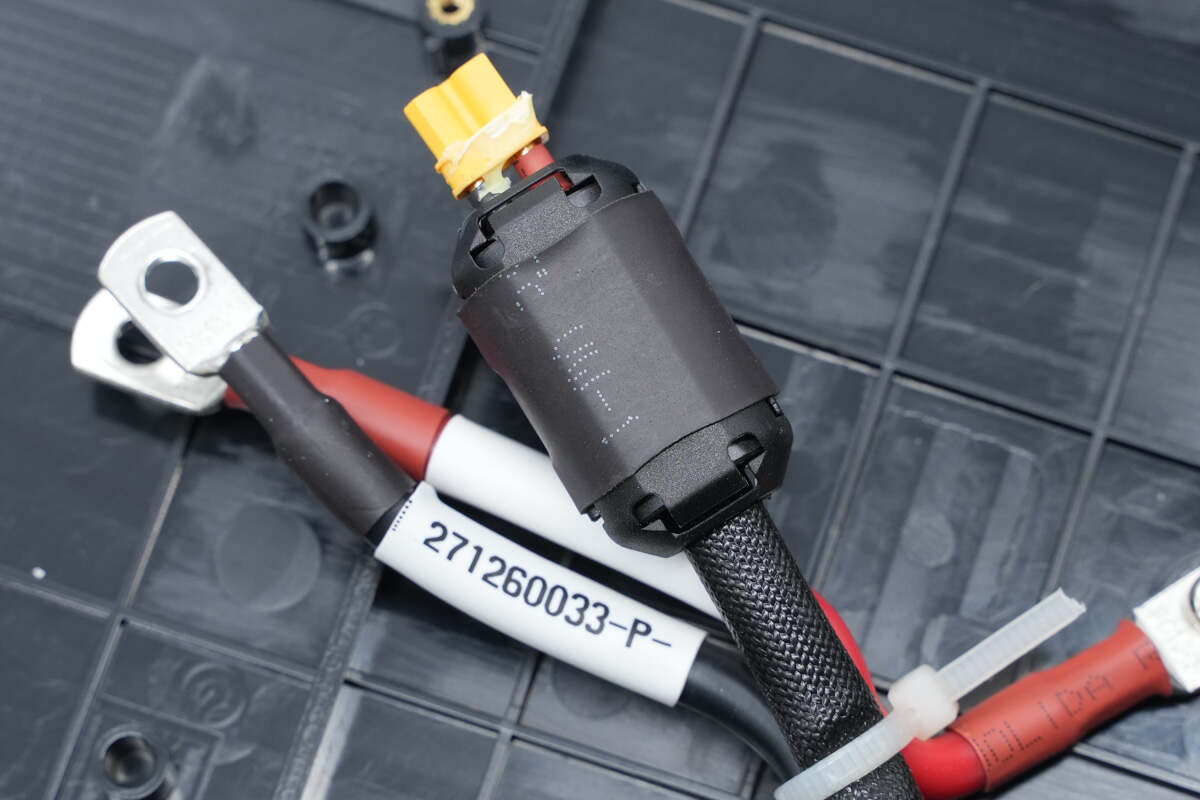
The output wire is protected from interference by a magnetic ring.
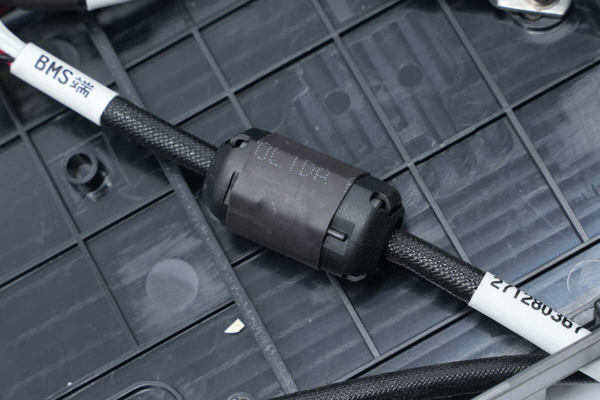
The communication wire is also protected against interference by magnetic rings.
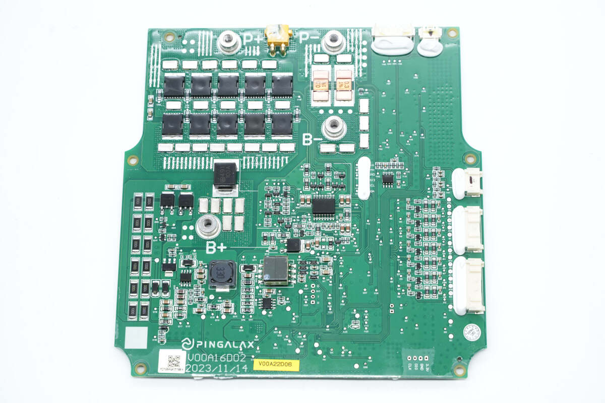
There are MOSFET, fuse, resistor, and buck circuit on the battery protection PCB.
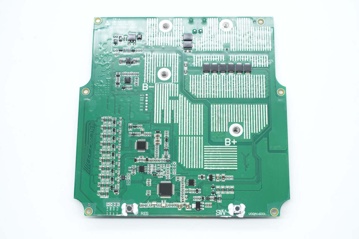
There are TVS, battery protection chip, and MCU on the back of the protection PCB.
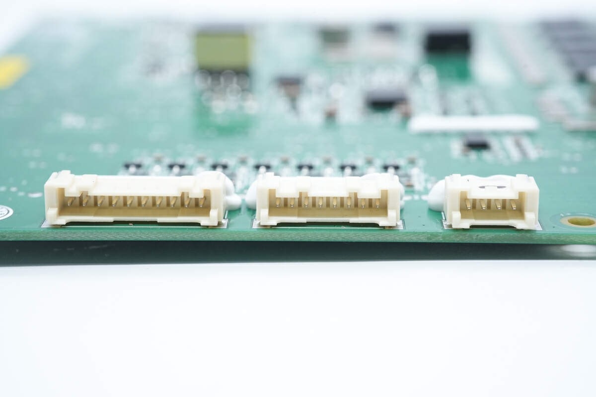
Here is the connector for the voltage sampling wires of the battery pack.
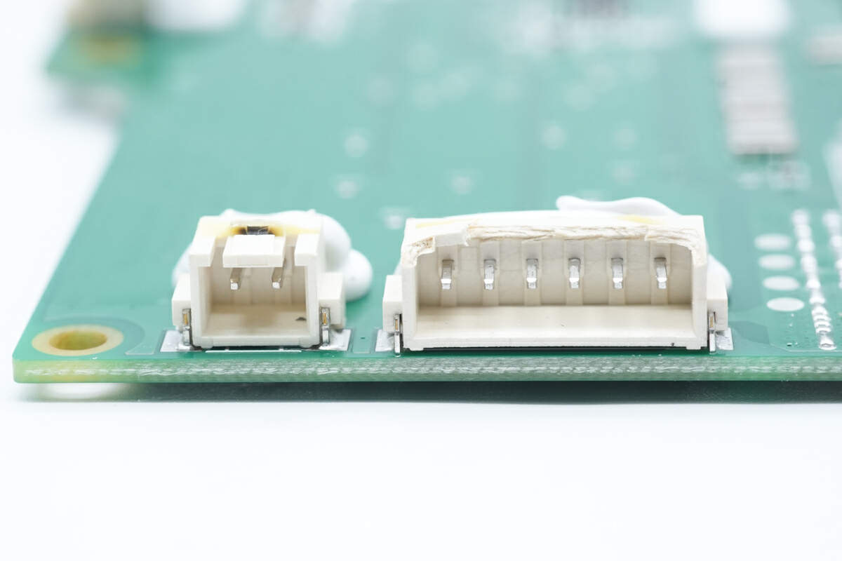
Here is the connector of the fast-charging PCB.
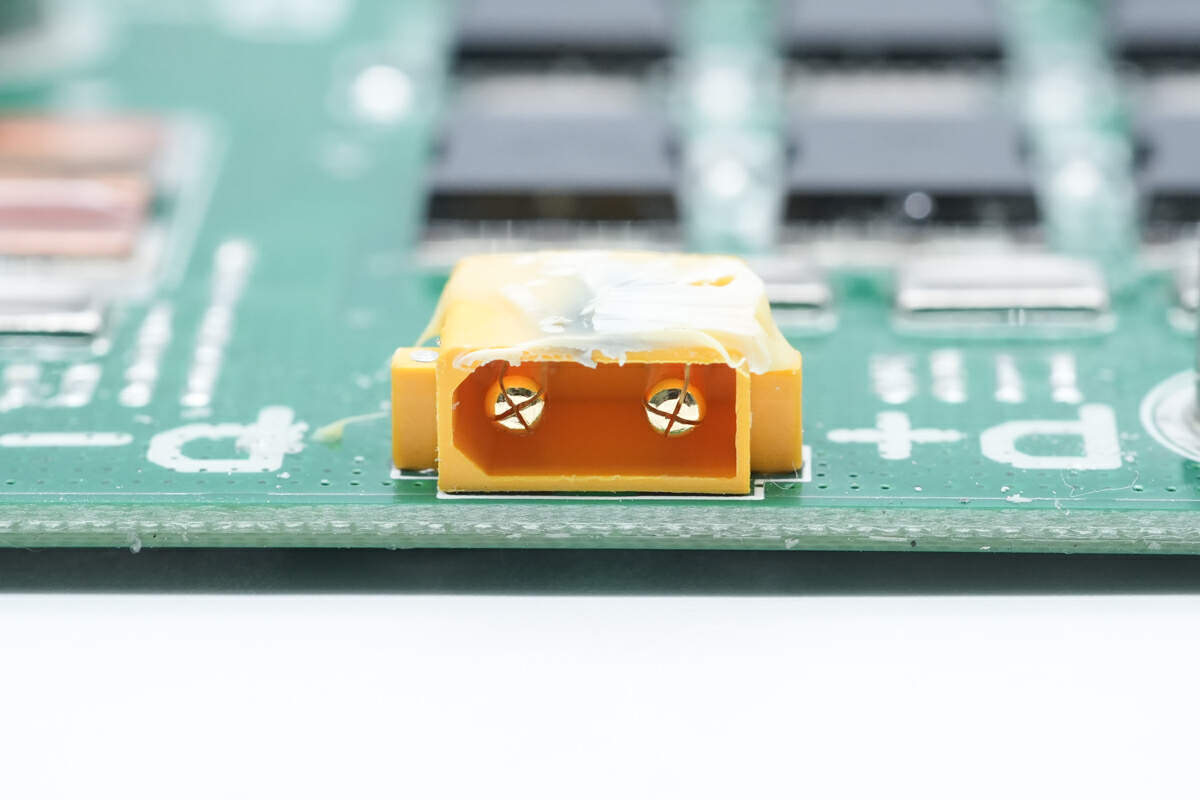
This is the XT30 connector.
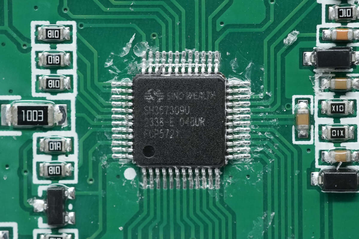
The battery protection chip is from SinoWealth. It has overcharge, over-discharge, temperature protection, charge and discharge overcurrent protection, short circuit protection, and other functions. Model is SH367309.
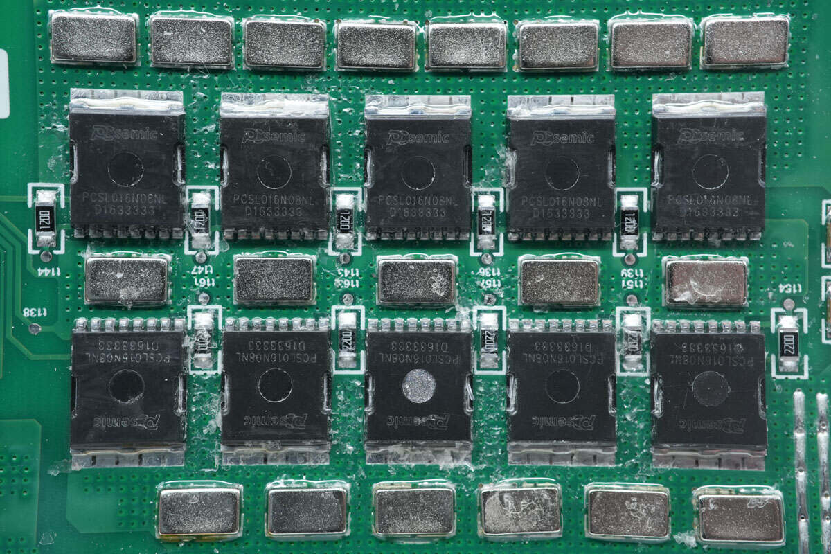
These are 10 battery protection MOSFETs.
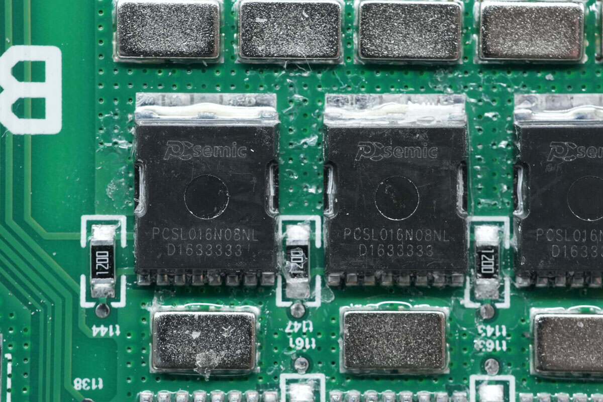
The battery protection MOSFETs are from PCsemic and adopt TOLL-1L package. Model is PCSL016N08NL. 80V 1.6mΩ.
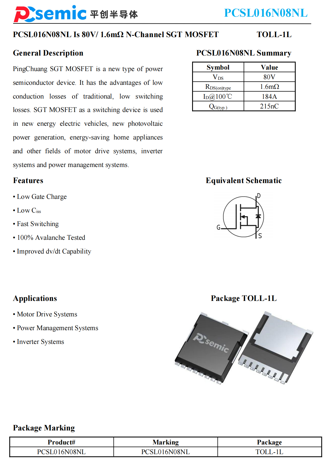
Here is all the information about PCsemic PCSL016N08NL.
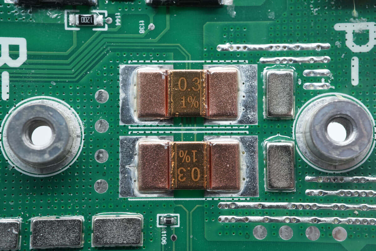
Two sampling resistors used for detecting the current of the battery packs are connected in parallel. 0.3mΩ.
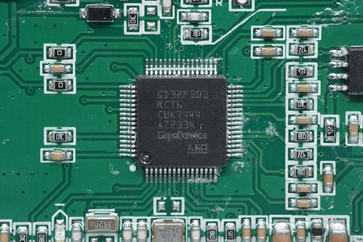
The MCU is from GigaDevice. Its frequency can reach 120MHz. It has a built-in Cortex-M4 core, 256KB FLASH, and 48KB SRAM. It also supports PWM signal output. Model is GD32F303RCT6.
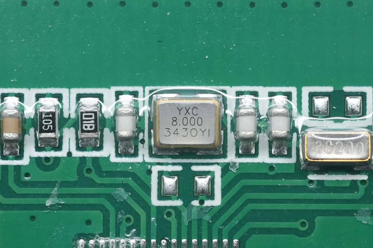
There is the 8.000MHz crystal oscillator.
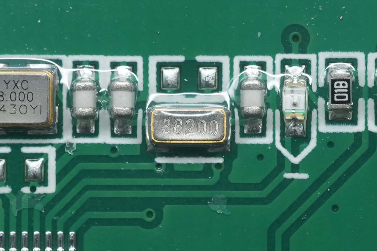
There is the 32.768KHz crystal oscillator.
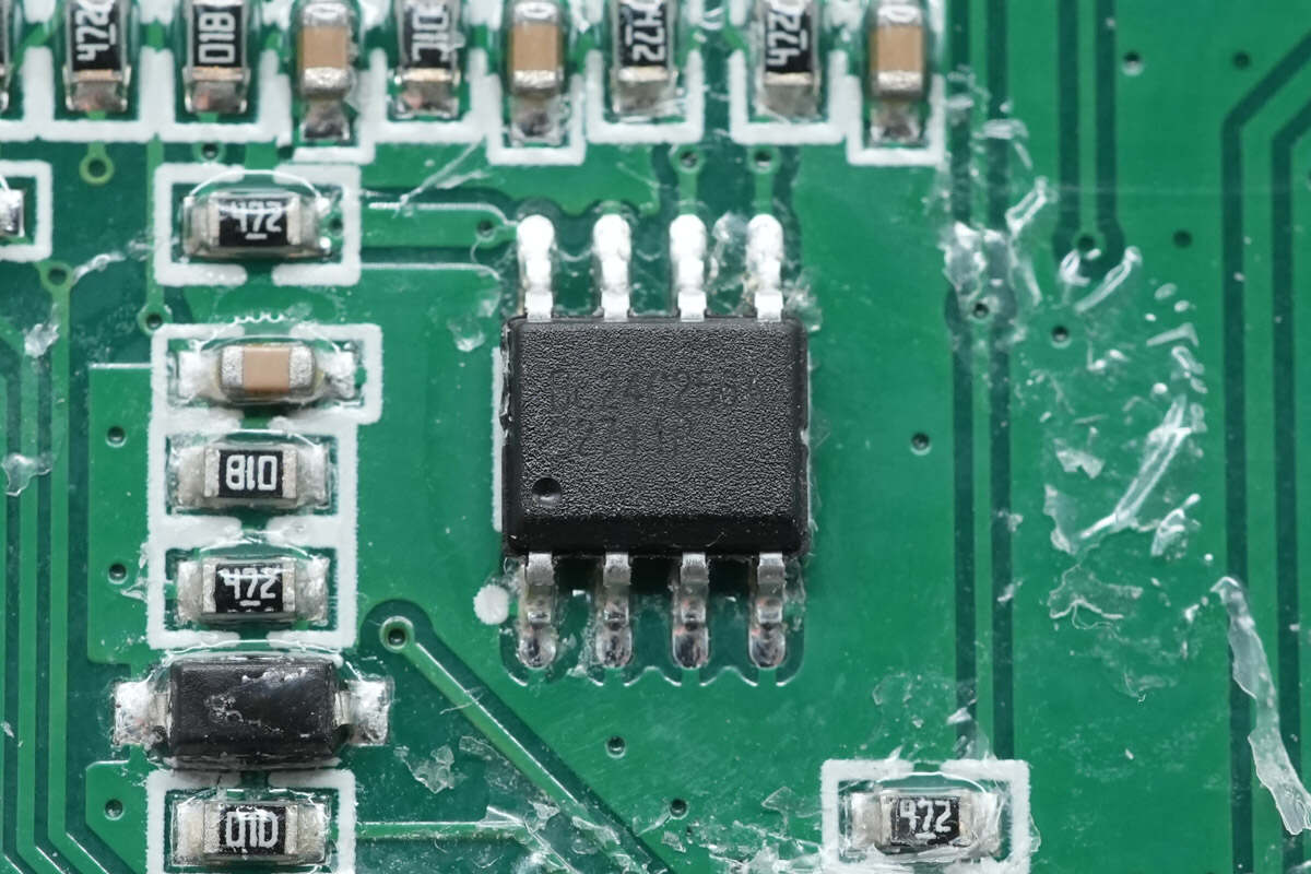
The memory chip is from Belling. The capacity is 256K bits. Model is BL24C256.
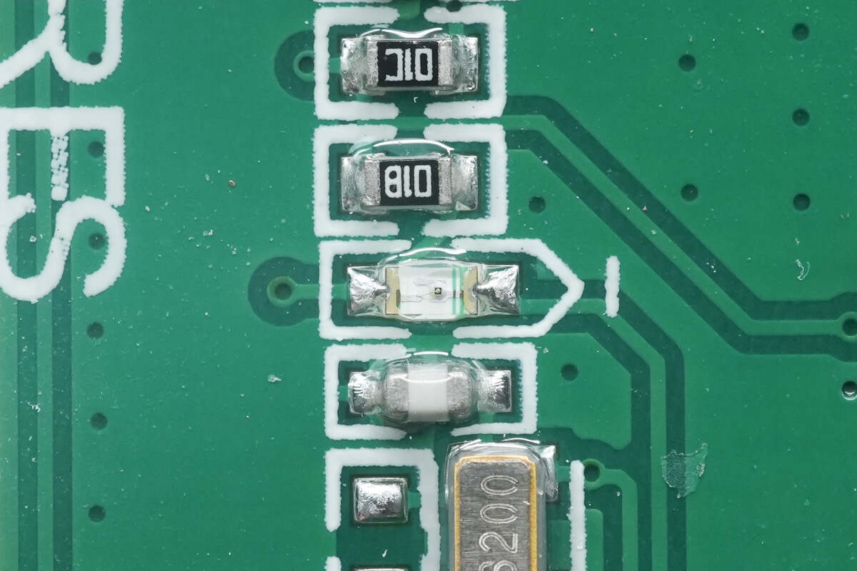
The SMD LED lights are used to indicate working status.
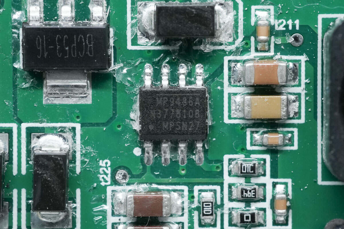
The buck chip is from MPS. It supports an input voltage of 100V and an output current of 3.5A. Model is MP9486A.
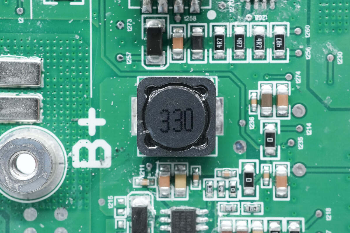
There is the buck inductor. 33μH.
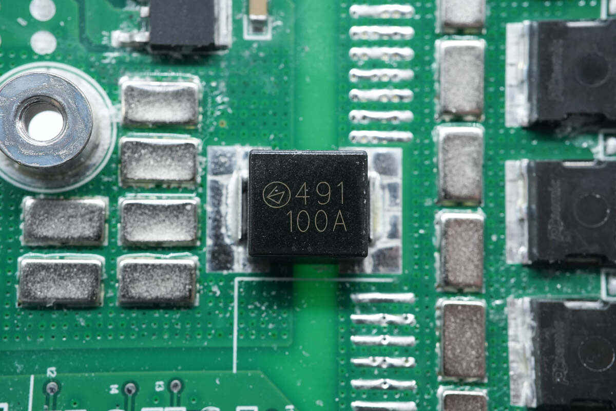
The SMD fuse marked with 491 is from Betterfuse. It is used to protect the battery pack from overcurrent. 100A.
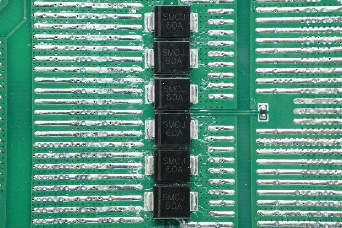
The TVS diodes are used to suppress surge voltage. There is the NTC thermistor on the right side to detect the temperature of the battery protection MOSFETs. Model is SMCJ60A.
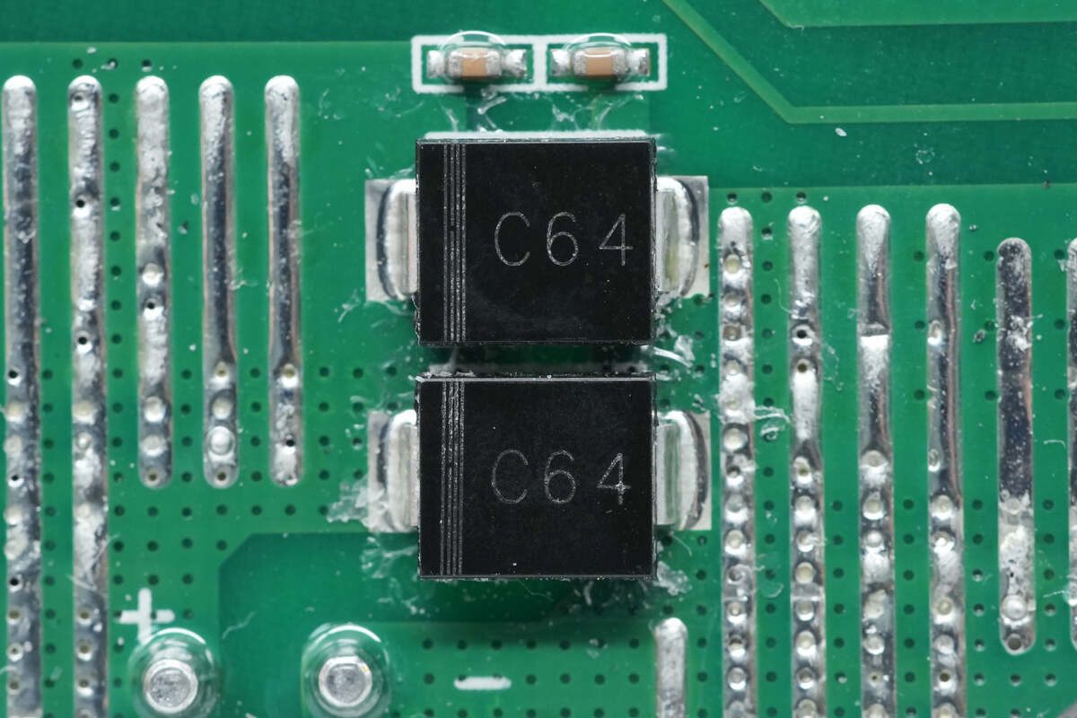
The TVS diodes marked with C64 are between the positive and negative of the output.
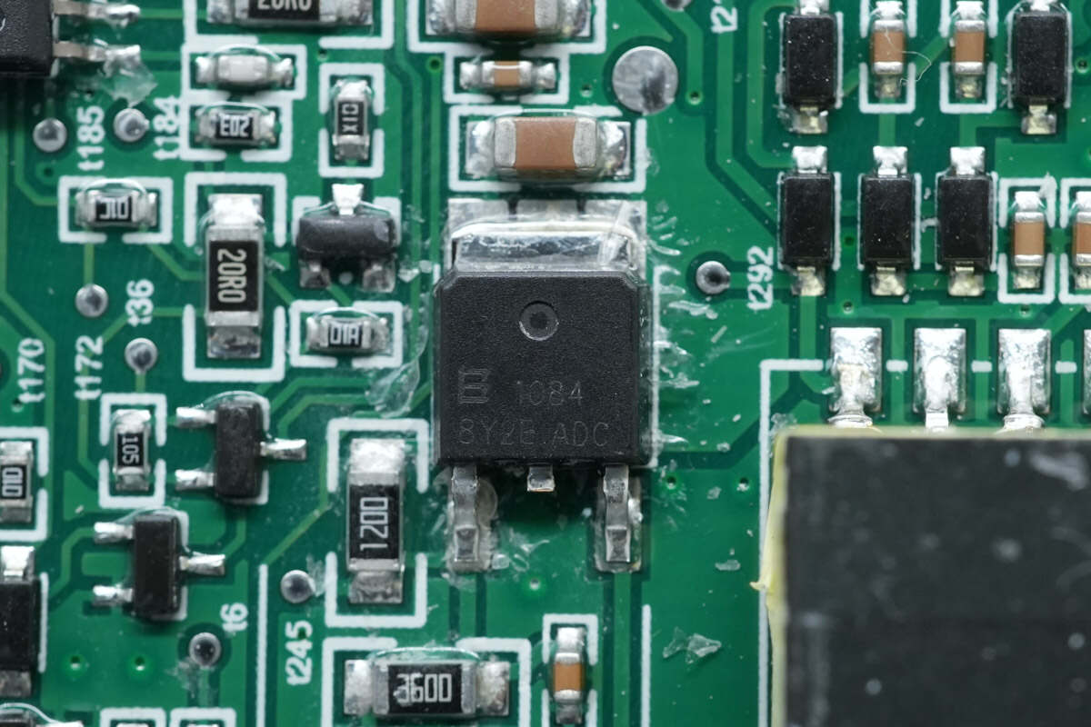
The regulator chip is from Belling and adopts TO252 package. Model is BL1084.
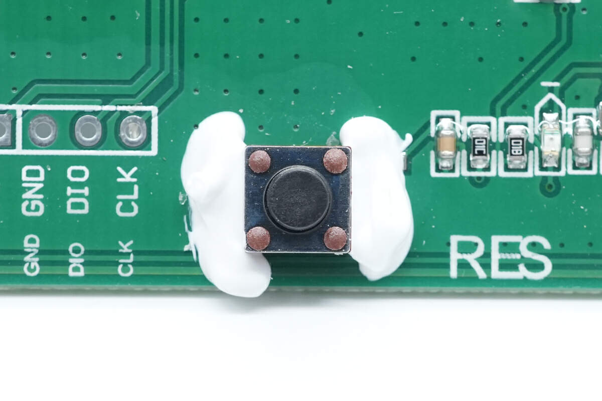
There is the reset switch.
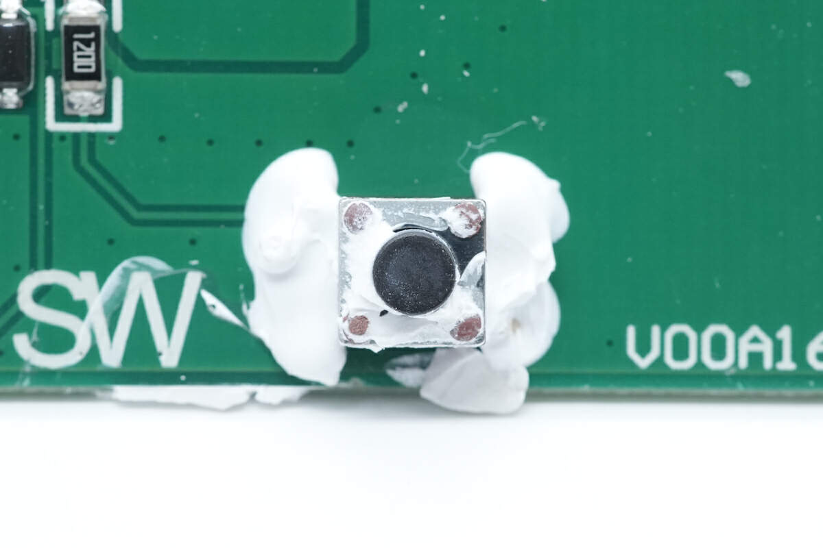
Here is the switch for output switching control of the protection PCB.
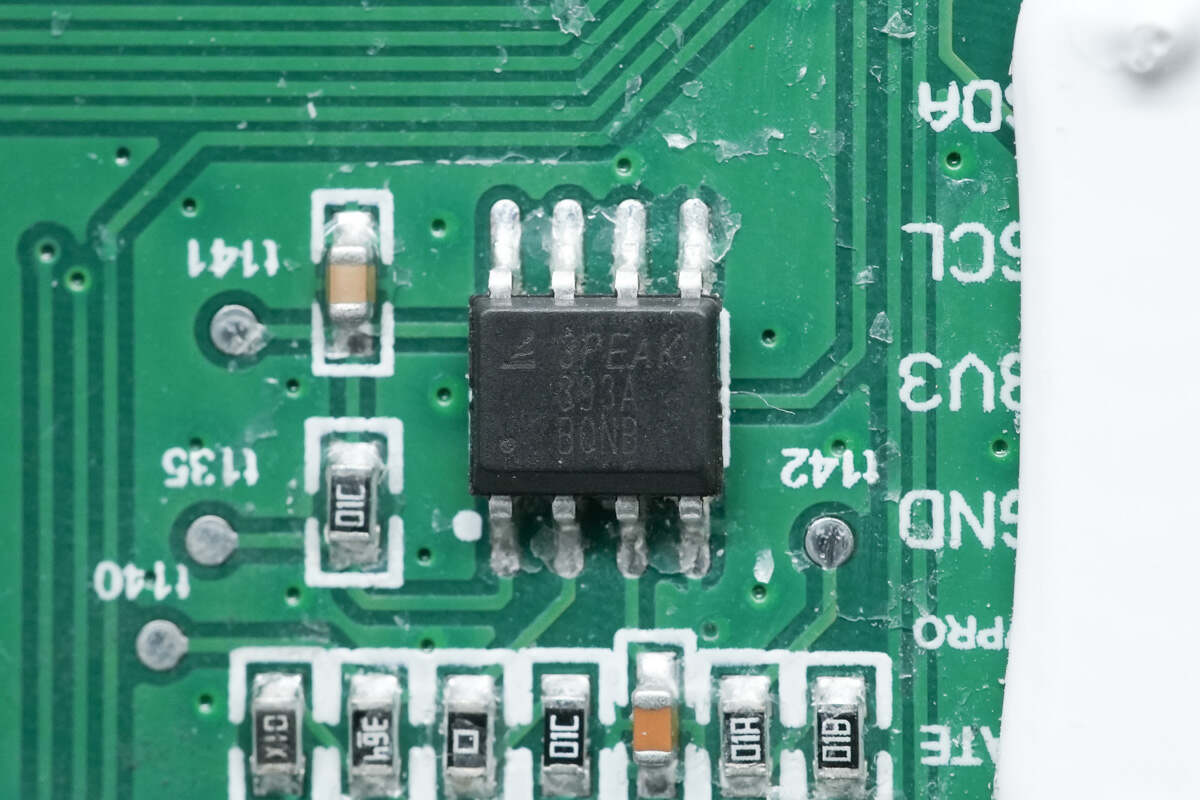
The dual voltage comparator is from 3PEAK. Model is LM393A.
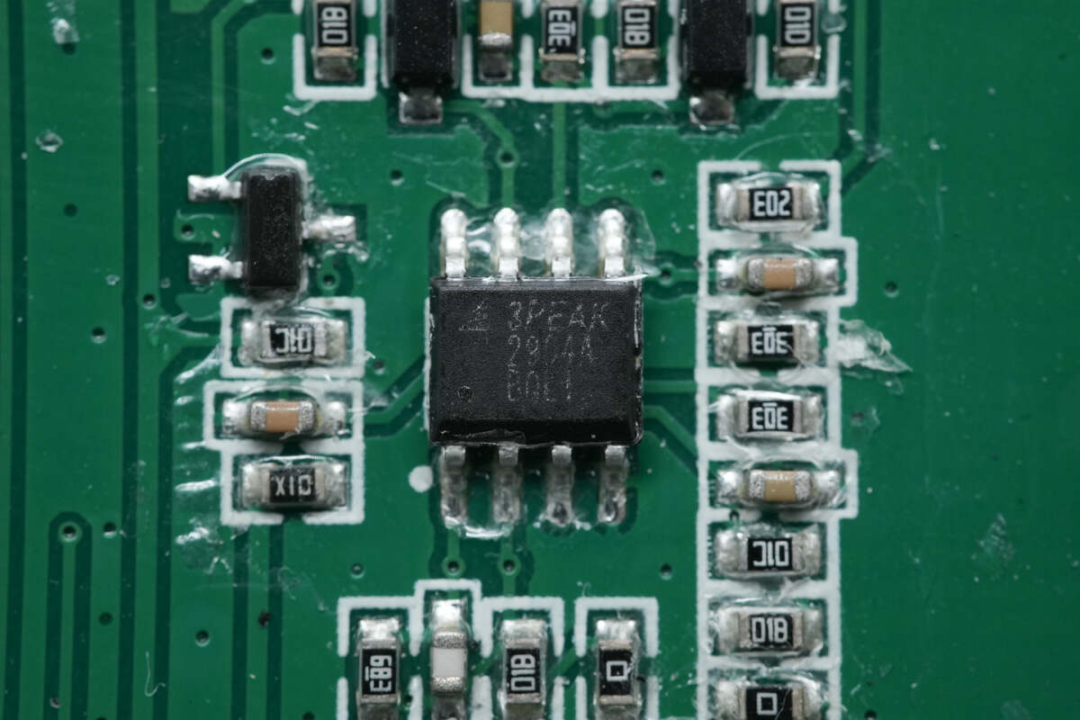
The dual Op Amp is also from 3PEAK. Model is LM2904A.

The transceiver chip is from MORNSUN. Model is SCM3406ASA.
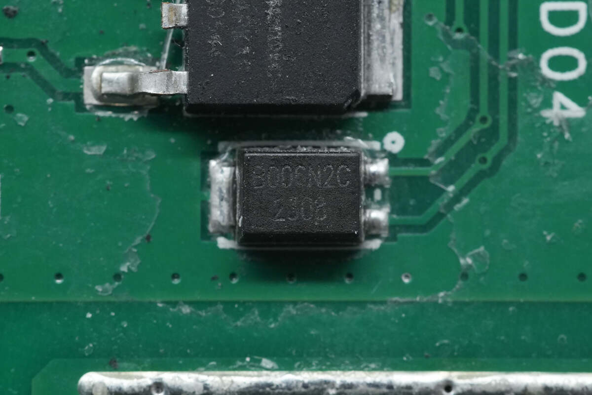
The TVS is from Bencent. Model is B006N2C.
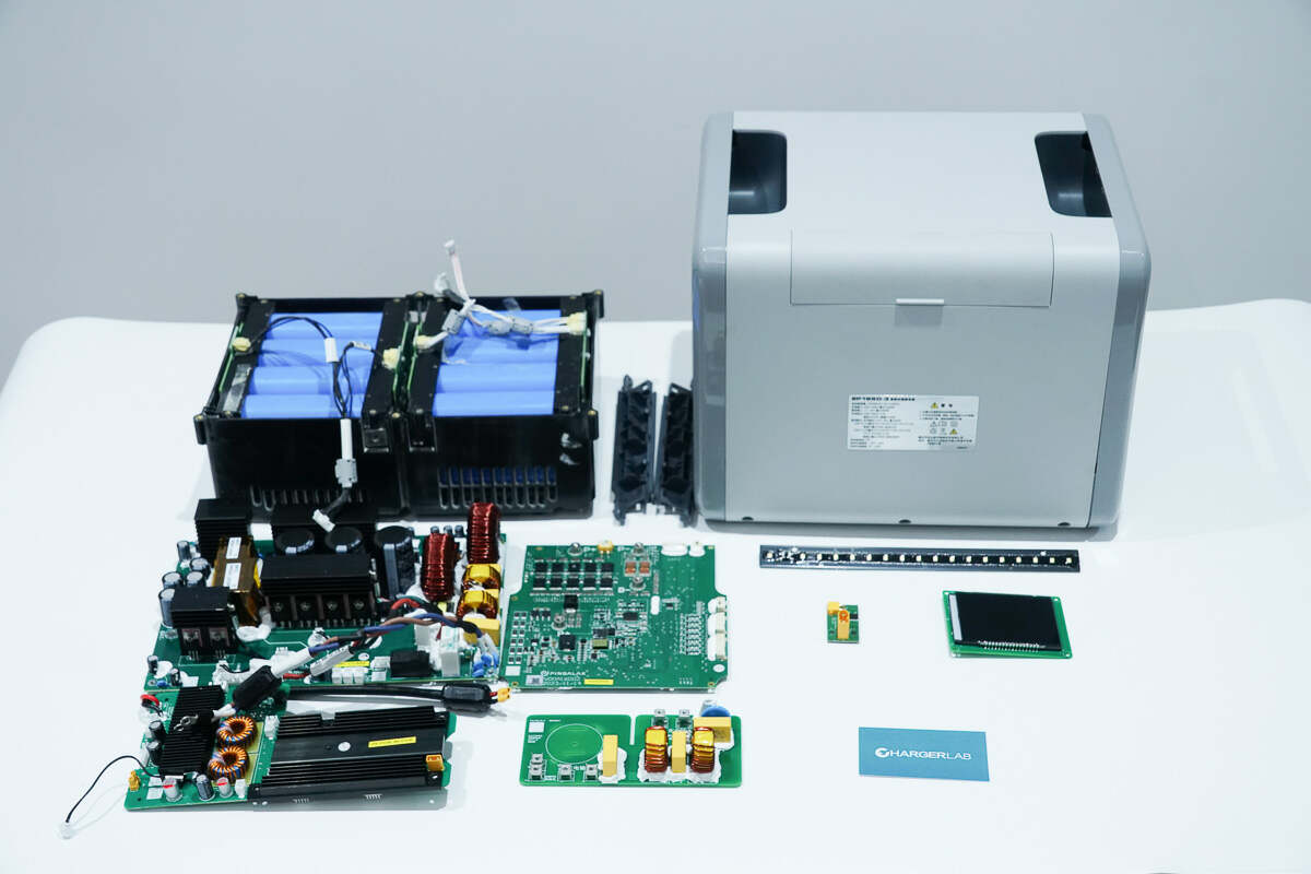
Well, those are all components of the EHOM EP1650 portable power station.
Summary of ChargerLAB
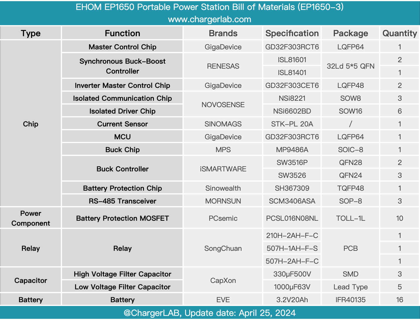
Here is the component list of the EHOM EP1650 Portable Power Station for your convenience.
It has a matte one-piece shell and two hidden handles on both sides of the top. It has LCD, USB ports, and AC inverter output ports on the front, as well as LED lights. It has a built-in LFP battery with a capacity of 1024Wh and supports a two-way inverter input of 1200W and an inverter output of 1650W. Each USB-C port supports fast charging of 100W and is independent from each other.
After taking it apart, we found it adopts a modular design. The interior is mainly composed of fast charging PCB, bidirectional inverter module, battery protection PCB, and battery pack. The power component is from PCsemic. The battery pack is composed of 16 40135 LFP batteries. The battery protection chip is from SinoWealth. The MCU used for communication functions is from GigaDevice.
The bidirectional inverter module uses two MCUs for control and uses an isolated driver for MOSFET driving. The digital isolator is used for communication between two MCUs. The fast-charging PCB is equipped with an MPPT circuit and uses a synchronous buck-boost controller for voltage conversion. The USB ports use two buck protocol chips from iSmartWare.
Each module in the power station is connected by connectors and binding posts to facilitate product assembly. The internal wires pass through the magnetic rings to suppress high-frequency interference. The bidirectional inverter module has a plastic case and is equipped with fans for heat dissipation.
Related Articles:
1. Review of EHOM EP1650 Portable Power Station
2. Review of Jackery Explorer 2000 Plus LiFePO4 Portable Power Station
3. Up to 3000W Output | Review of VTOMAN FlashSpeed 1500 Power Station

