Introduction
Recently, we disassembled a Dell 165W adapter. And today, we got another product also from Dell, which is a server power supply. It has passed the 80 PLUS Platinum standard. And it supports an output of 12V 41.25A, which is 495W. And it is manufactured by Delta.
It features a light guiding handle for easy access. Now, let's take it apart to see its internal components and design.
Product Appearance
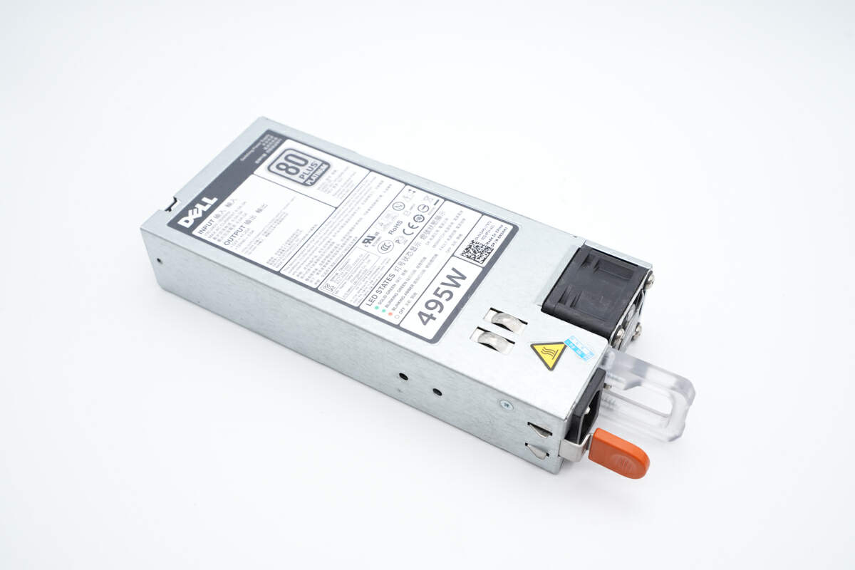
As you can see, it is a very ordinary power supply.
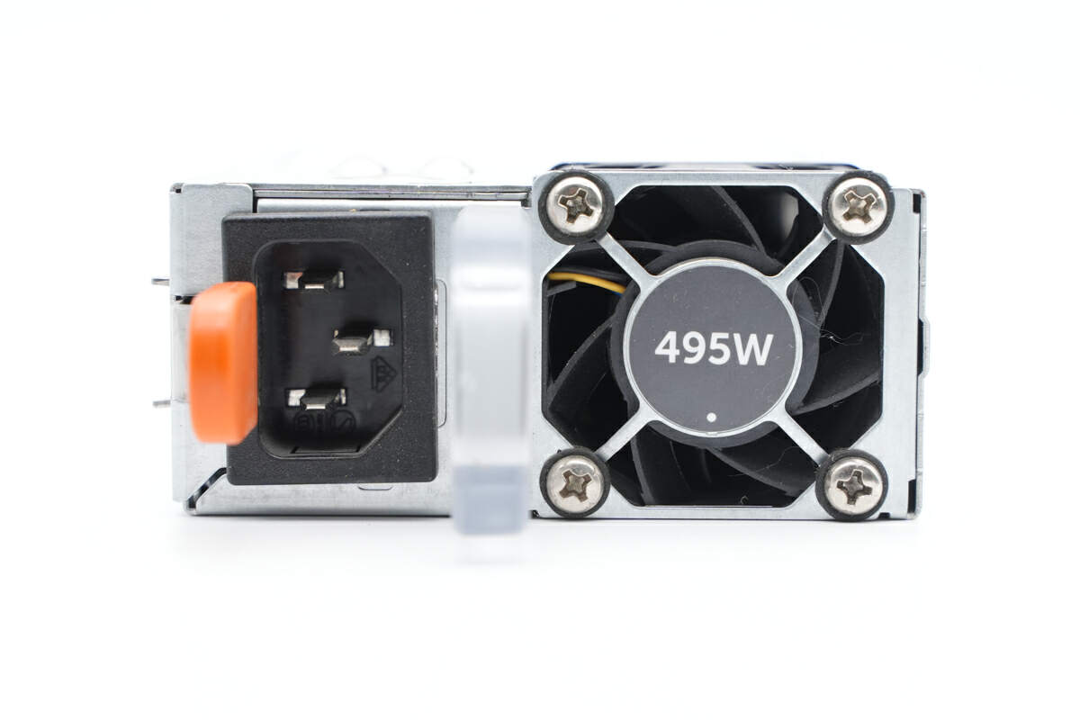
There is an AC socket and a fan on the front. The fan is fixed with screws.
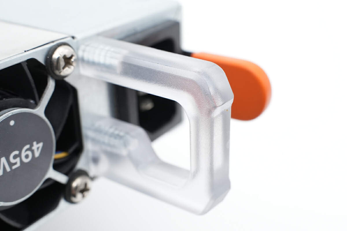
The light guiding handle can be used as an indicator.
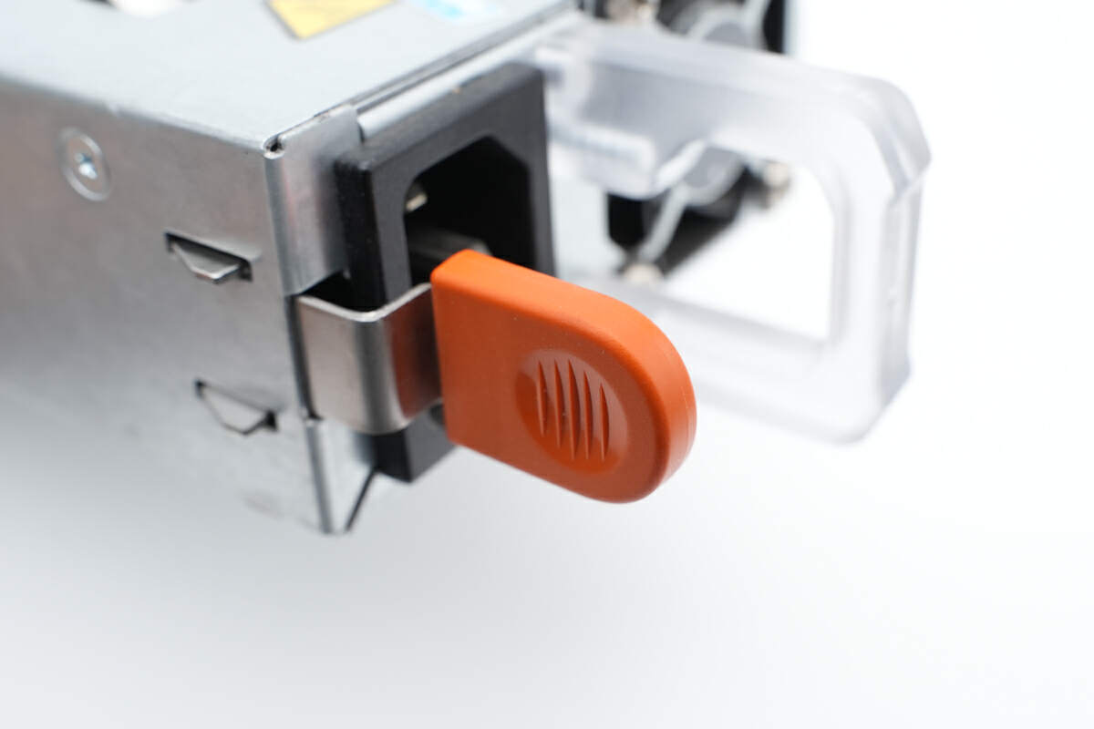
The orange handle near the AC socket is used for quick release.
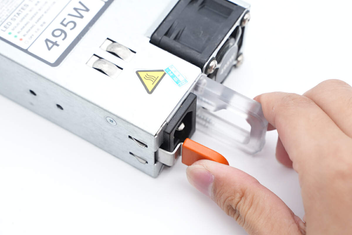
You can take out the power supply by pressing the two handles.
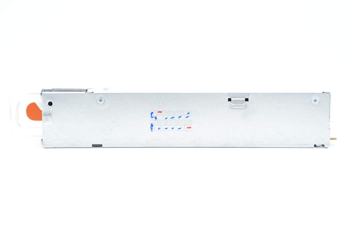
Its metal case is fixed by screws.
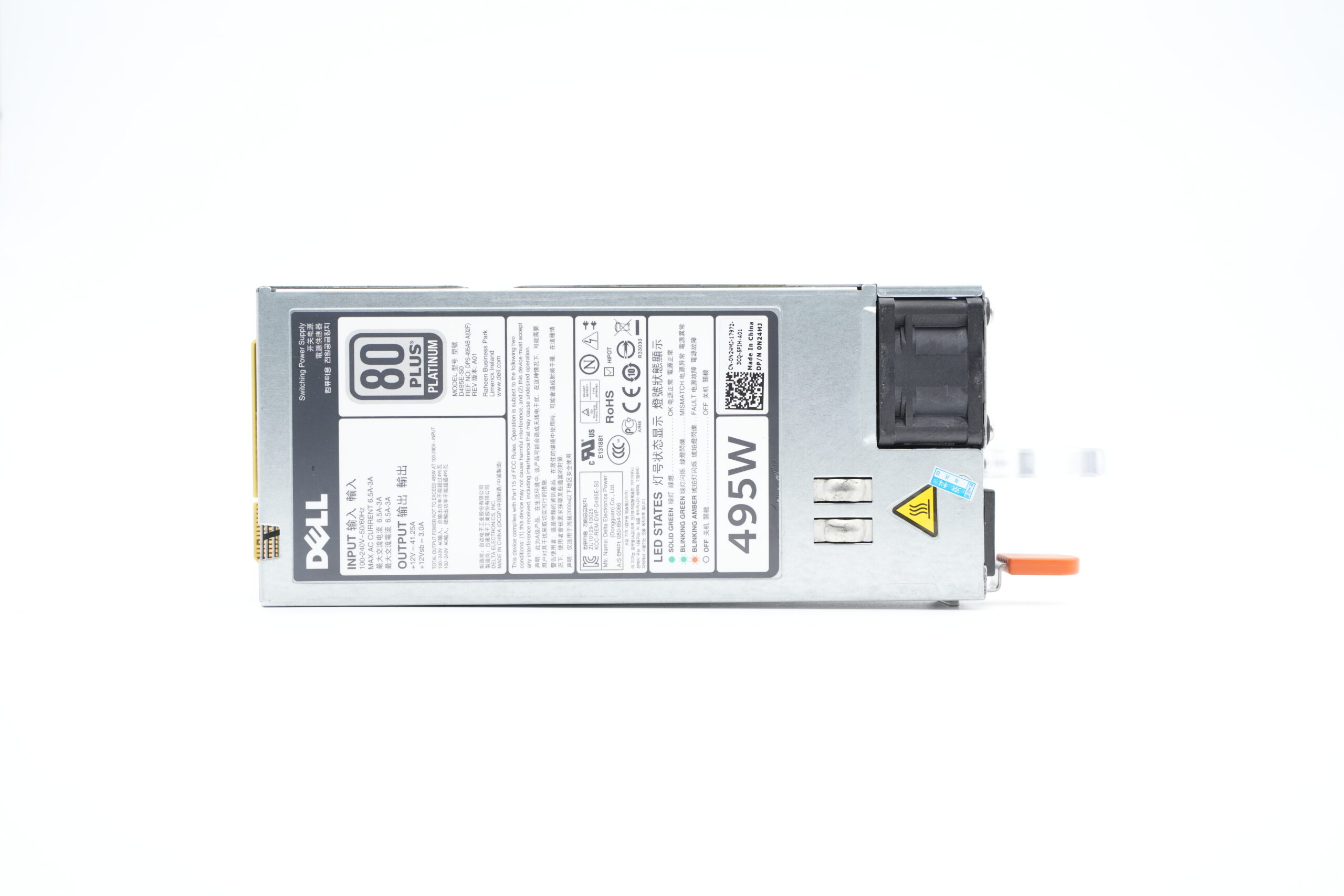
All specs info are printed on this sticker.
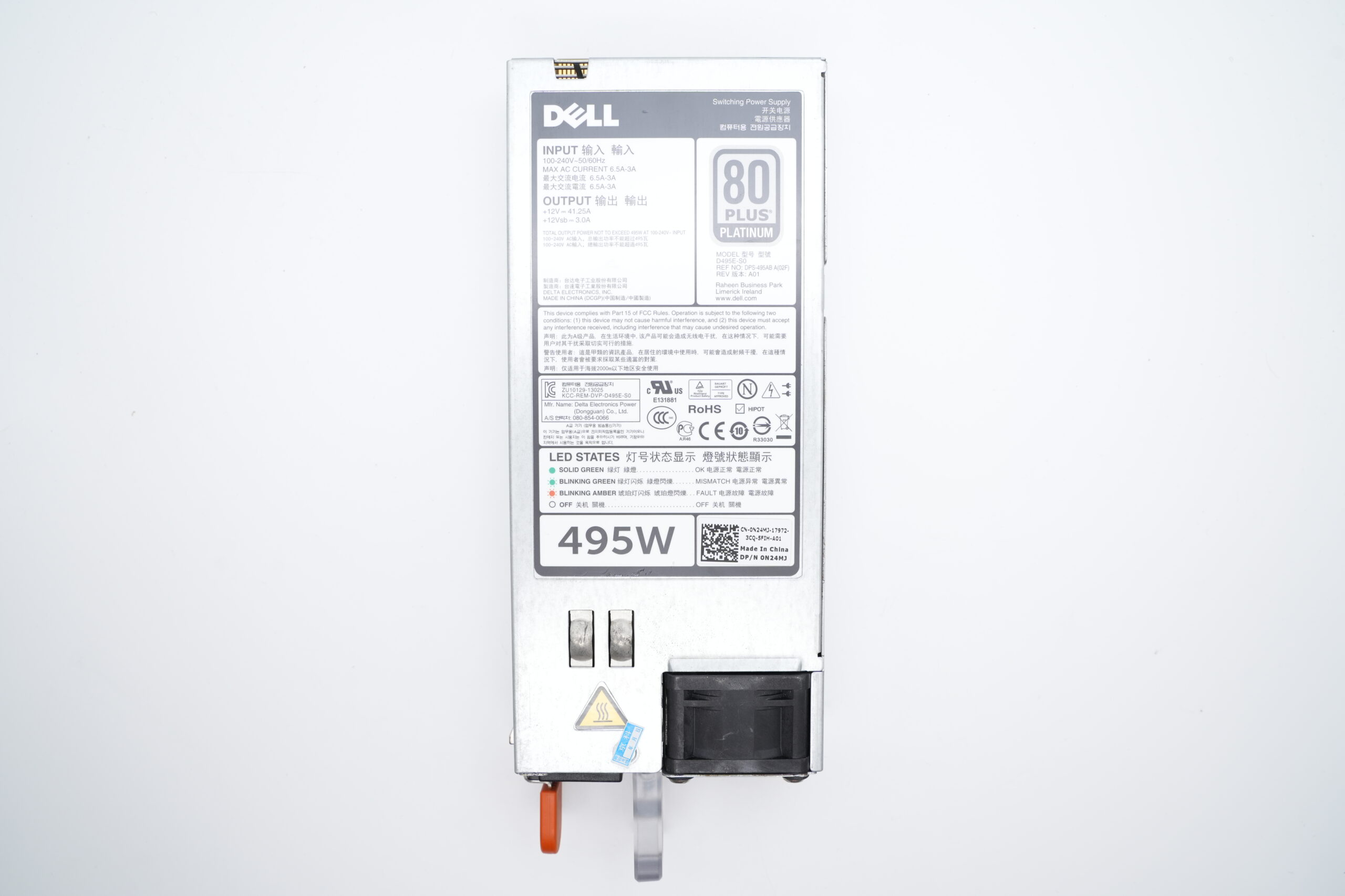
Model is D495E-S0. It can support input of 100-240V~50/60Hz 6.5A-3A. And it can support output of +12V⎓41.25A and +12Vsb⎓3A. Manufacturer is Delta. It has passed CE and KC certifications. As mentioned at the beginning, it has passed the 80 PLUS Platinum standard.
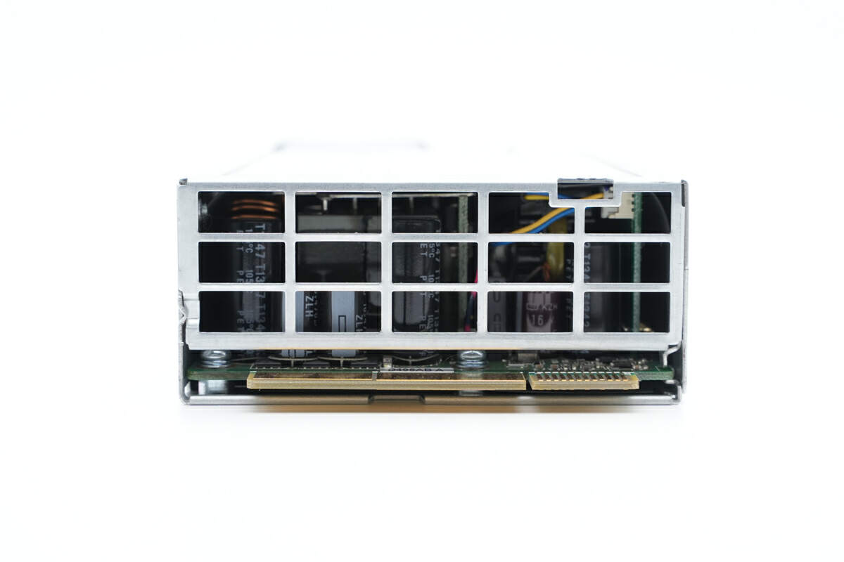
The output end has ventilation for heat dissipation.
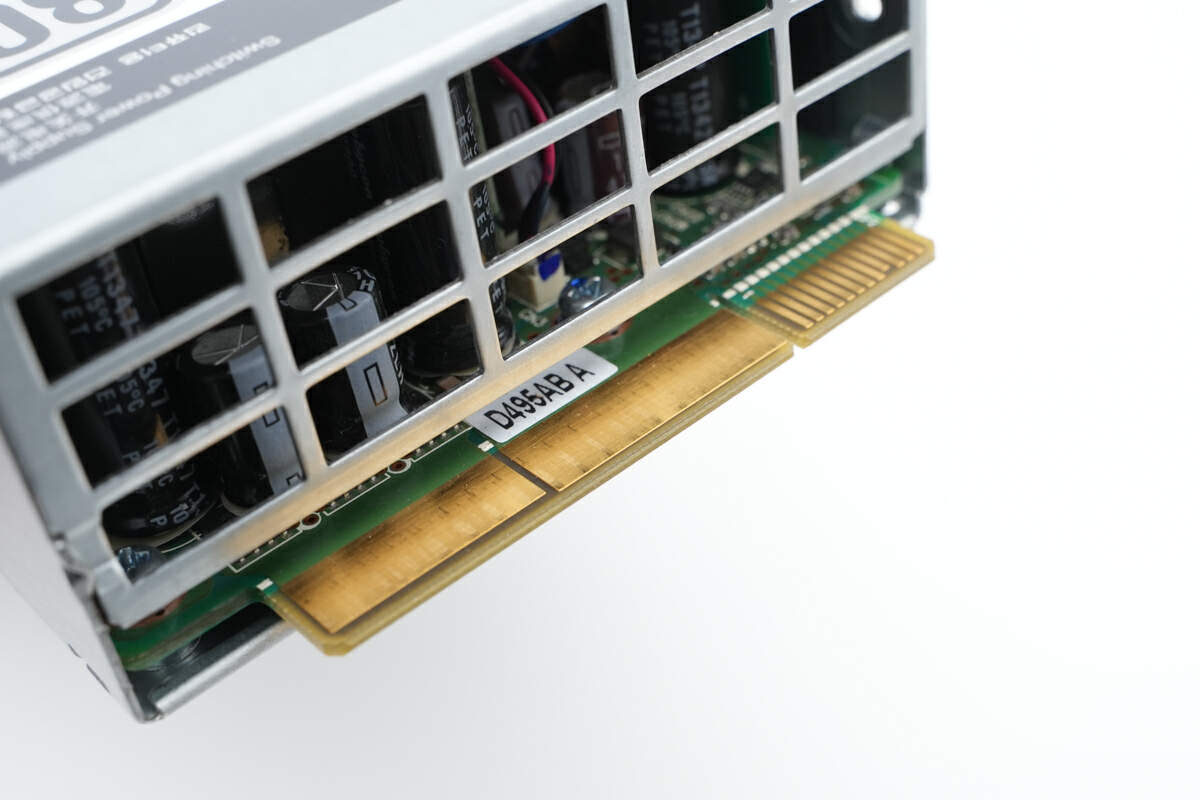
Here are the PCB gold fingers.
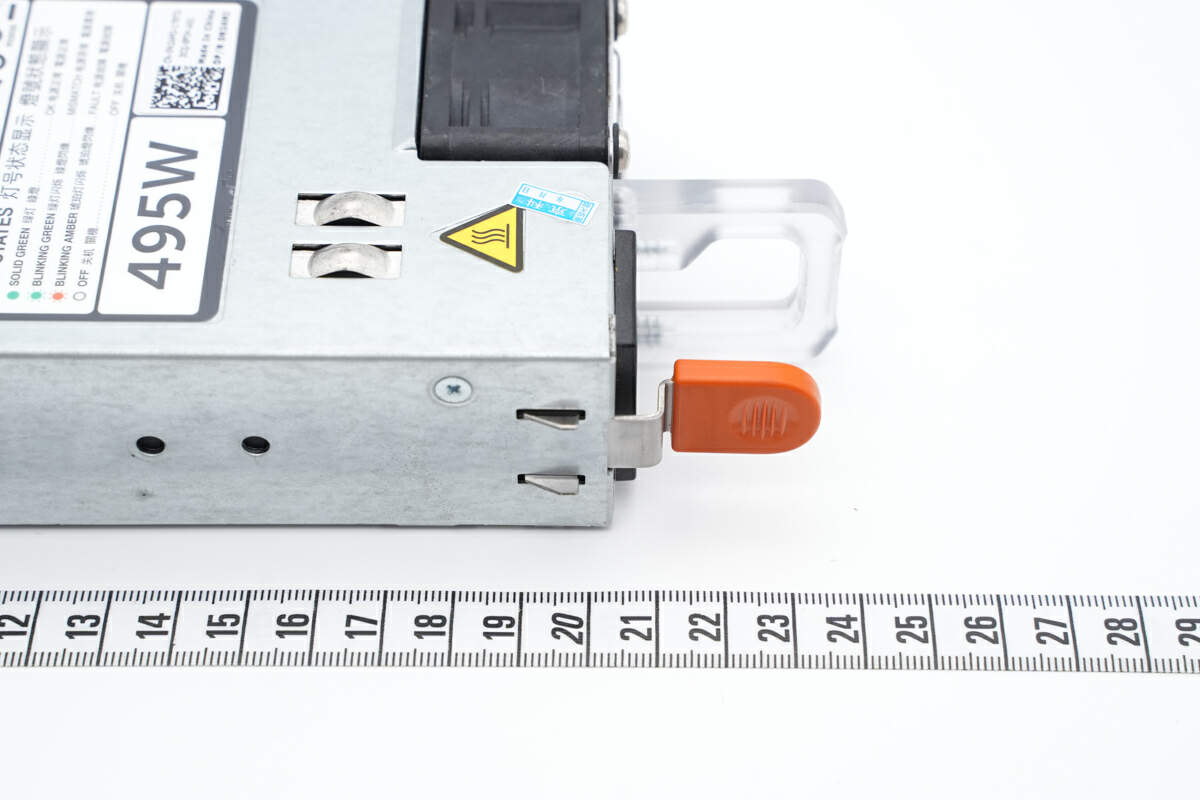
The length of it is about 20 cm (7.87 inches) (excluding the handles and PCB gold fingers).
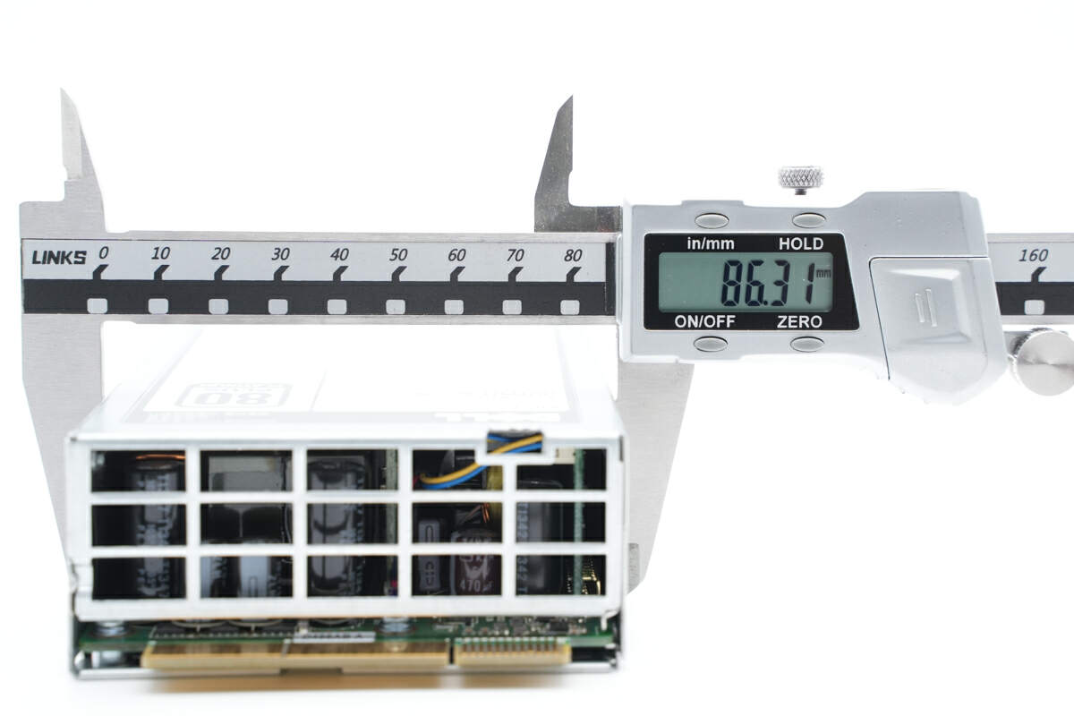
The width is about 86 mm (3.39 inches).
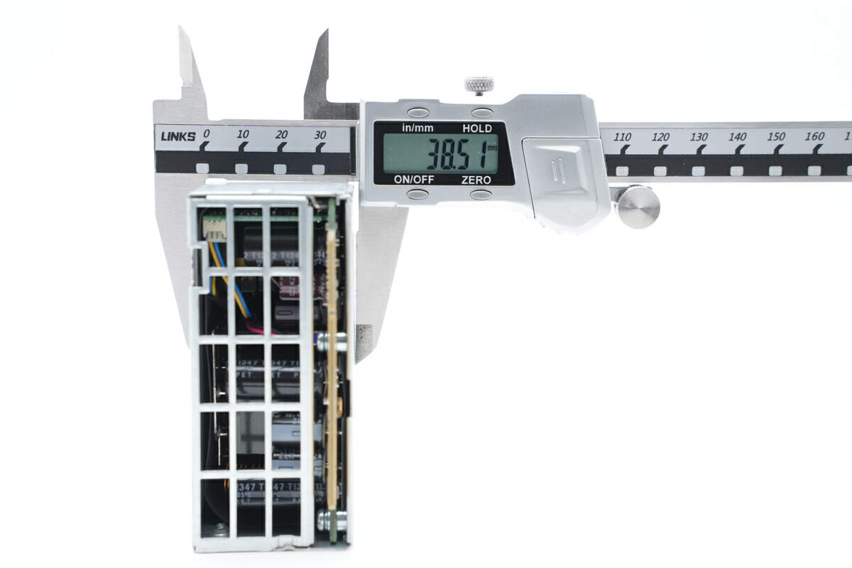
And the thickness is about 39 mm (1.54 inches).
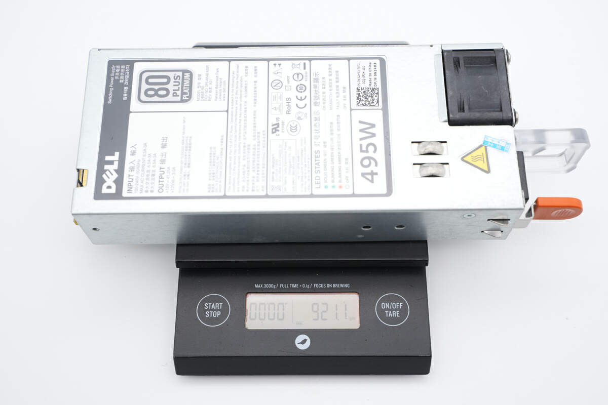
The weight is about 921 g (32.49 oz).
Teardown
Next, we will take it apart.
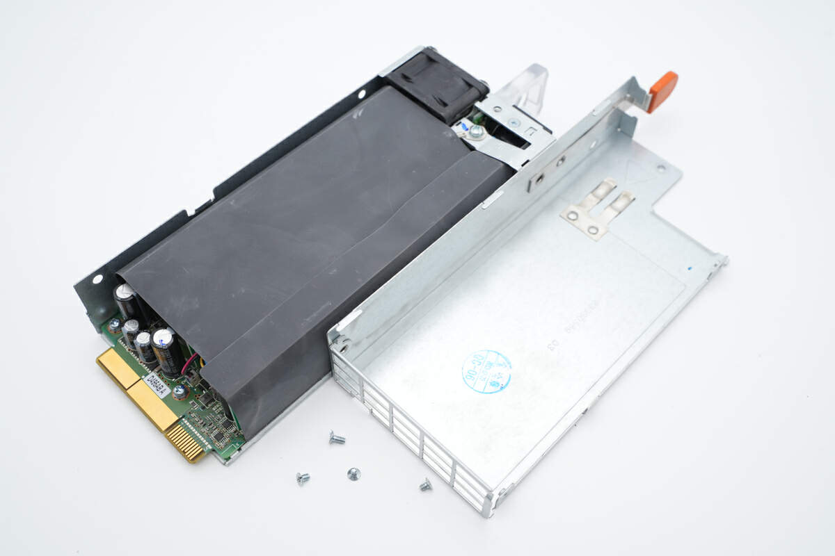
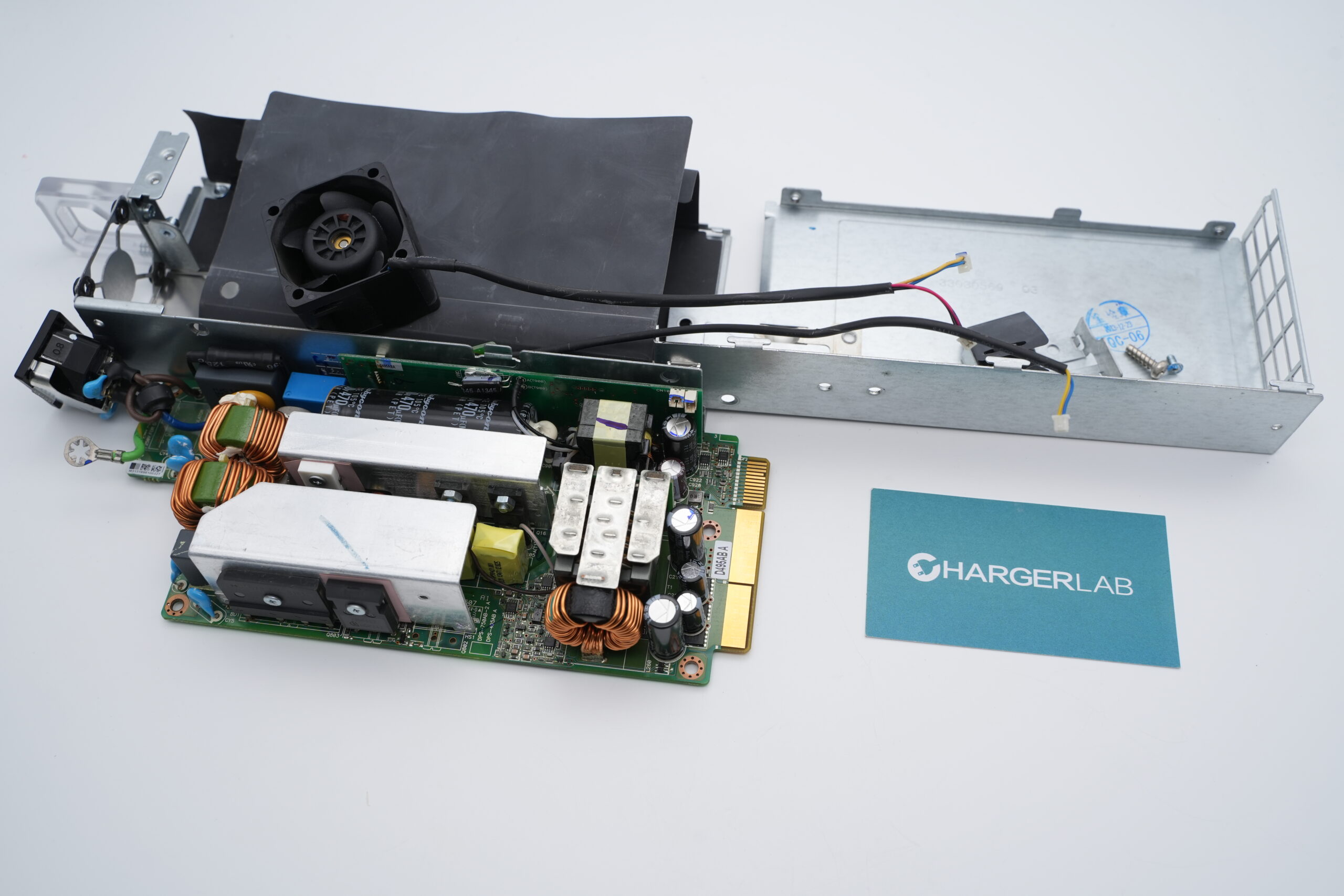
Unscrew the fixing screws and remove the upper case. The PCBA module is insulated by black mylar sheets.
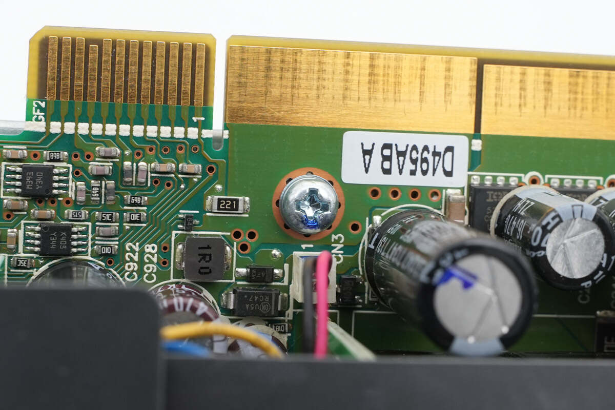
The PCBA module is fixed on the bottom case by screws.
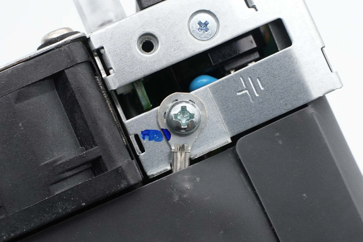
The ground wire is also fixed with screws.
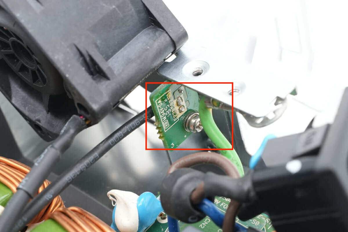
So is the indicator light PCB.
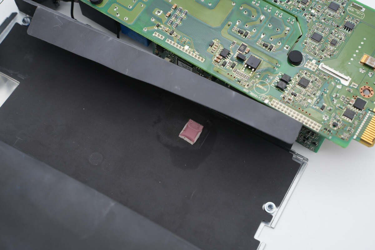
There is a tiny thermal pad paste on the mylar sheets to dissipate heat for a chip on the PCBA.
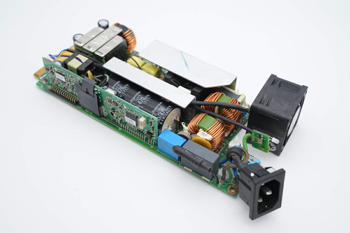
As mentioned, there is an AC socket and a fan on the input end.
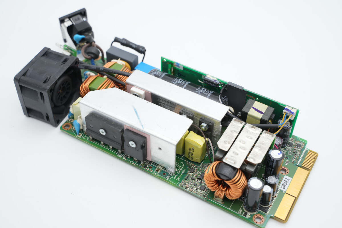
And there are PCB gold fingers on the output end.
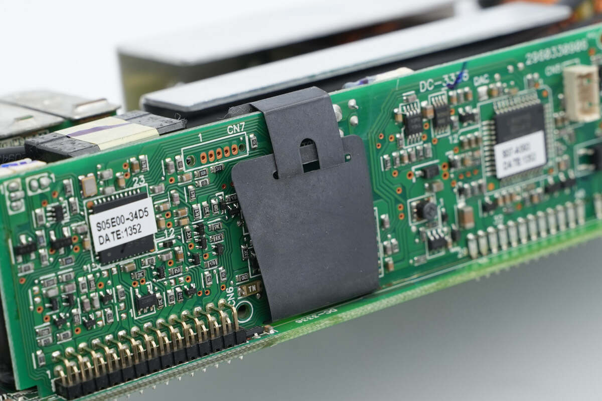
The vertical PCB is insulated by a small mylar sheet.
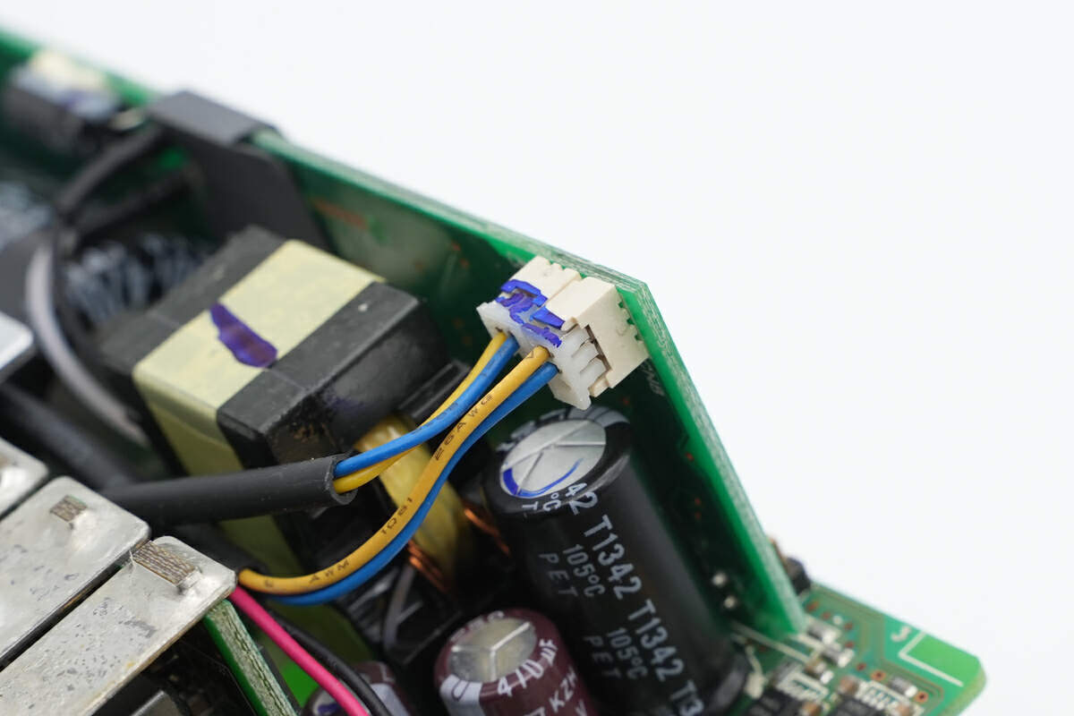
The wires of the fan and indicator light are connected to this vertical PCB.
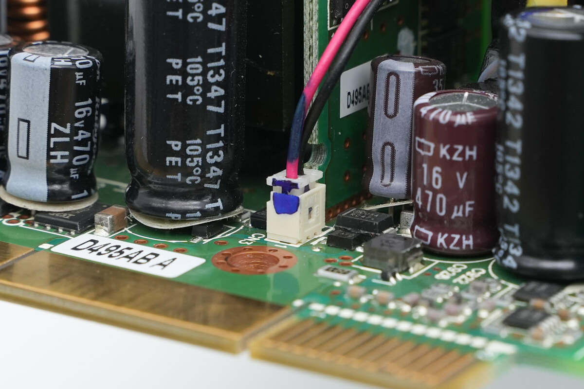
The power supply wires of the fan are connected to the main PCB.
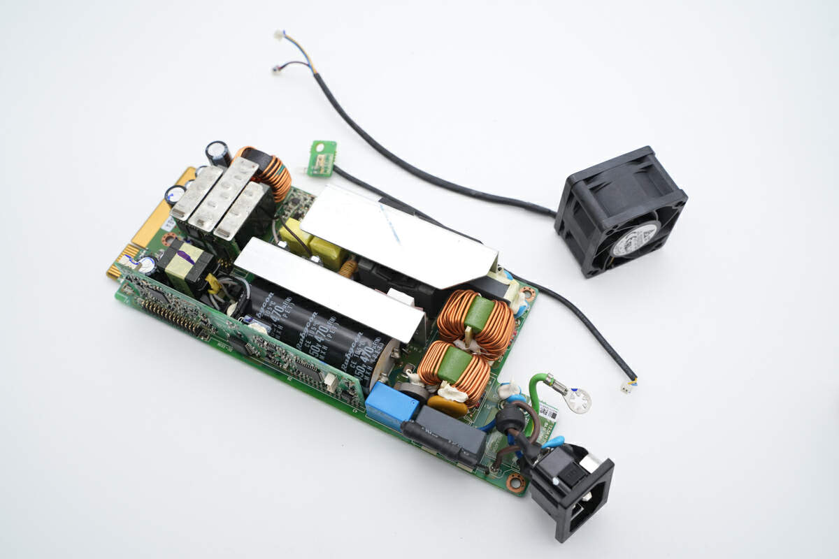
Disconnect the fan from the PCBA.
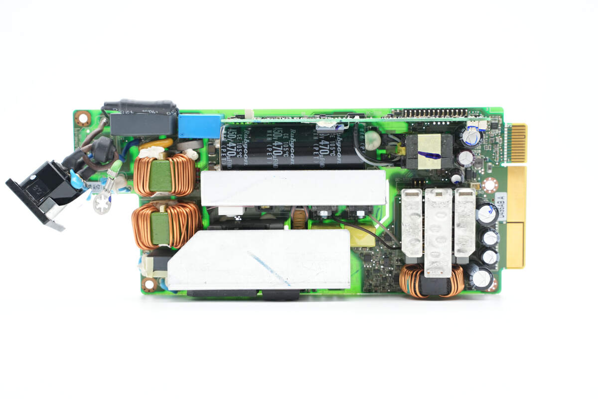
There are fuse, safety X2 capacitor, varistor, common mode choke, inductor, capacitor, and transformer.
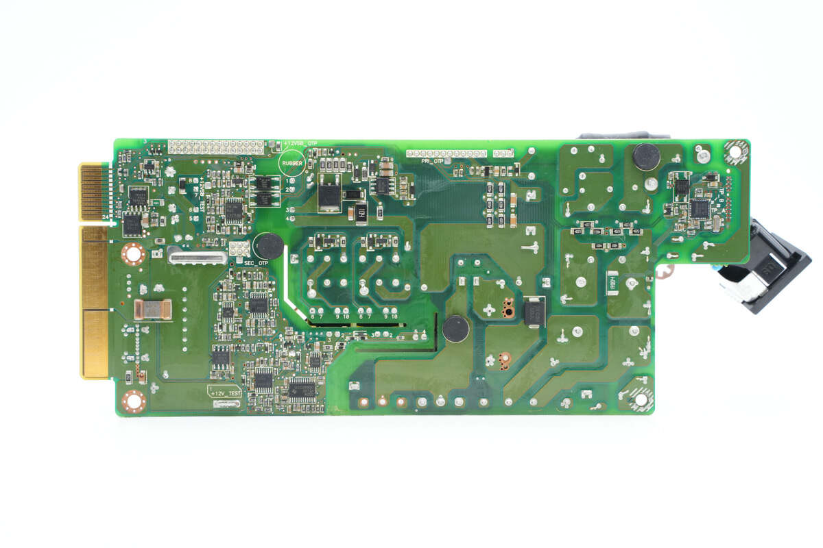
The power measurement IC, primary master control chip, master control chip for auxiliary power supply, MOSFET, and sampling resistor are on the back.
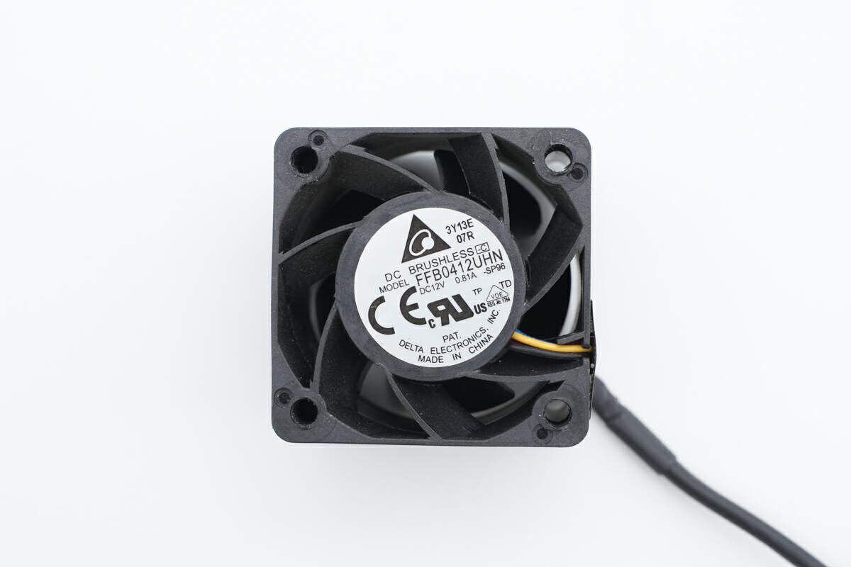
The fan is from Delta. Model is FFB0412UHN. 12V 0.81A.
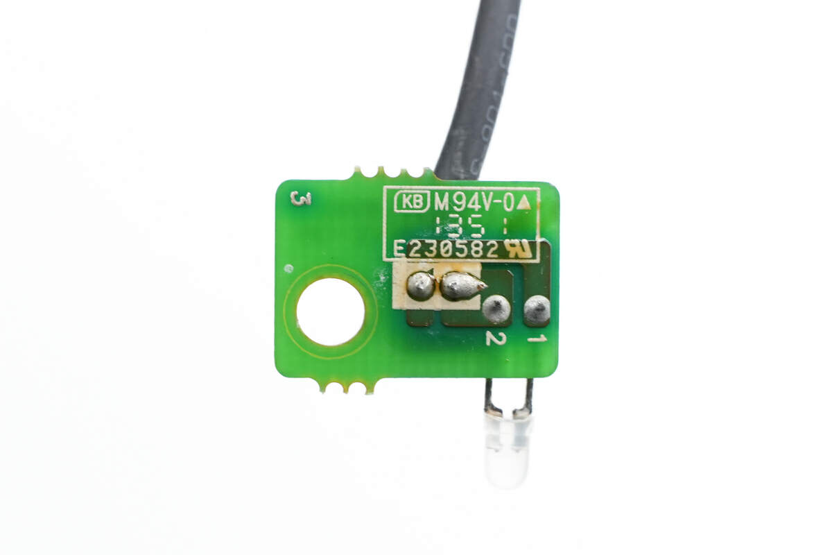
The PCB of the indicator light is connected by wire.
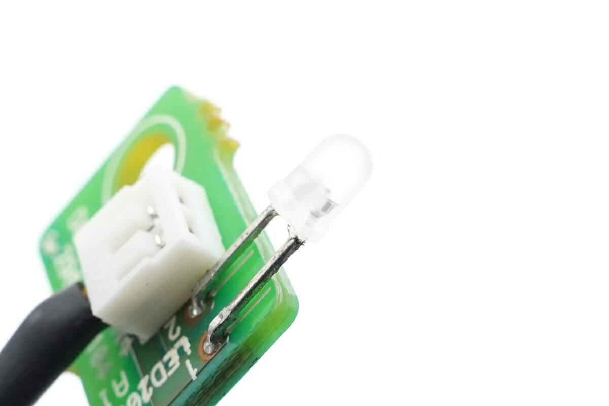
Here is the two-color indicator light.
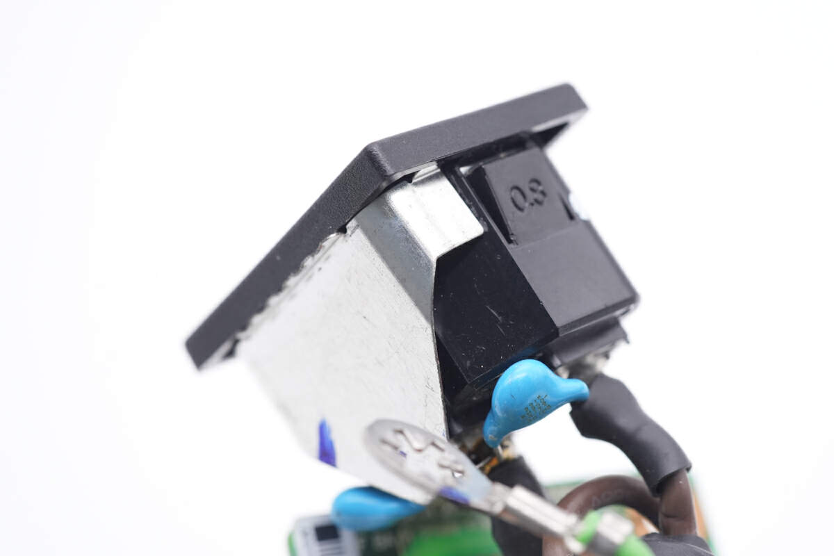
The AC socket has an iron piece that contacts the case for grounding.
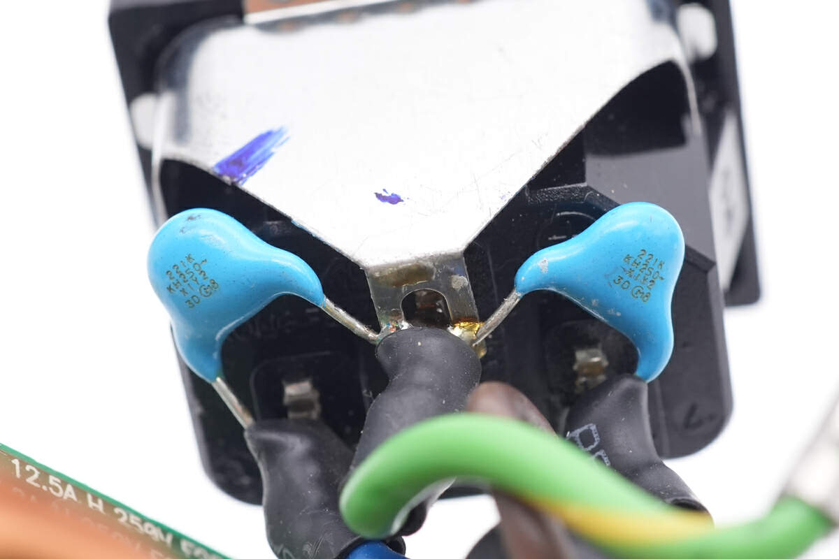
Two blue Y capacitors are soldered to the AC socket.
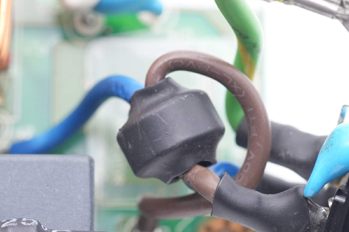
The input wire passes through the toroidal core to suppress high-frequency interference.
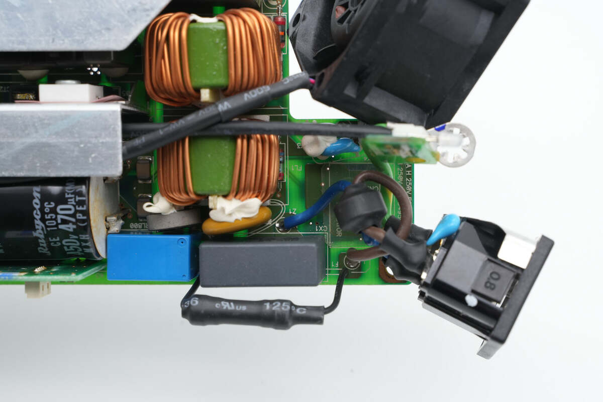
And the input wires are soldered on the PCBA.
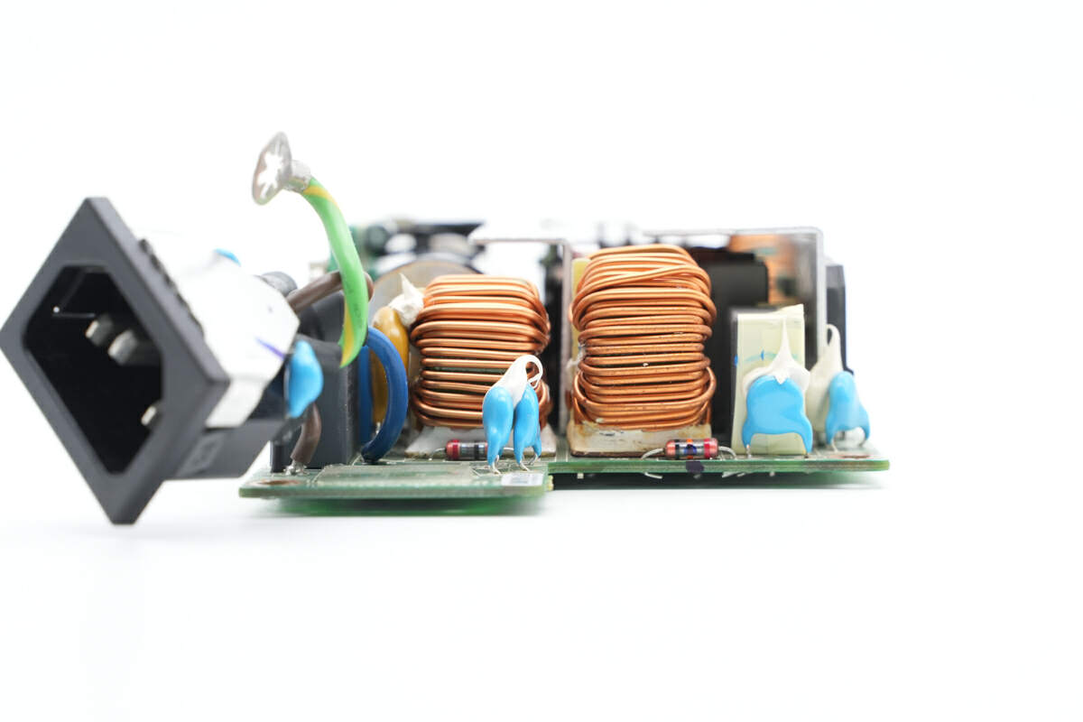
Two common mode chokes and many blue Y capacitors are at the input end.
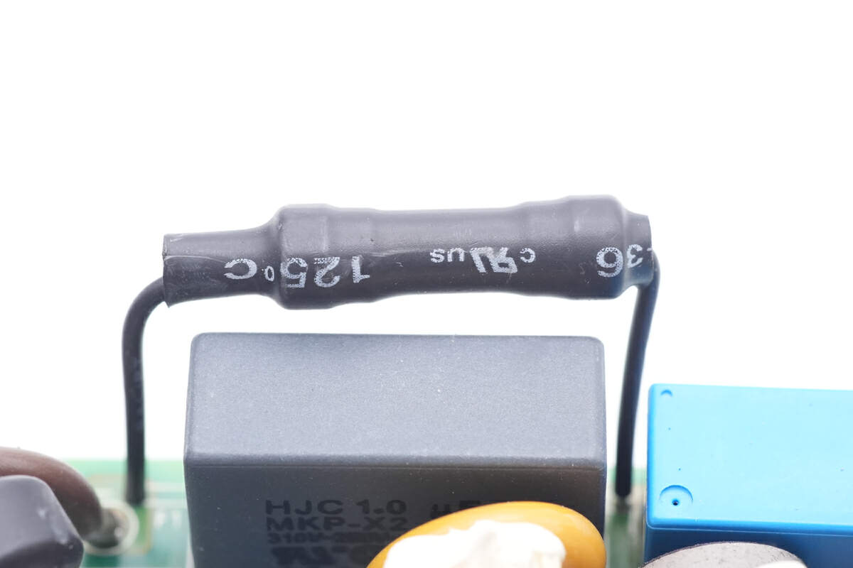
The input fuse is insulated via heat-shrinkable tubing.
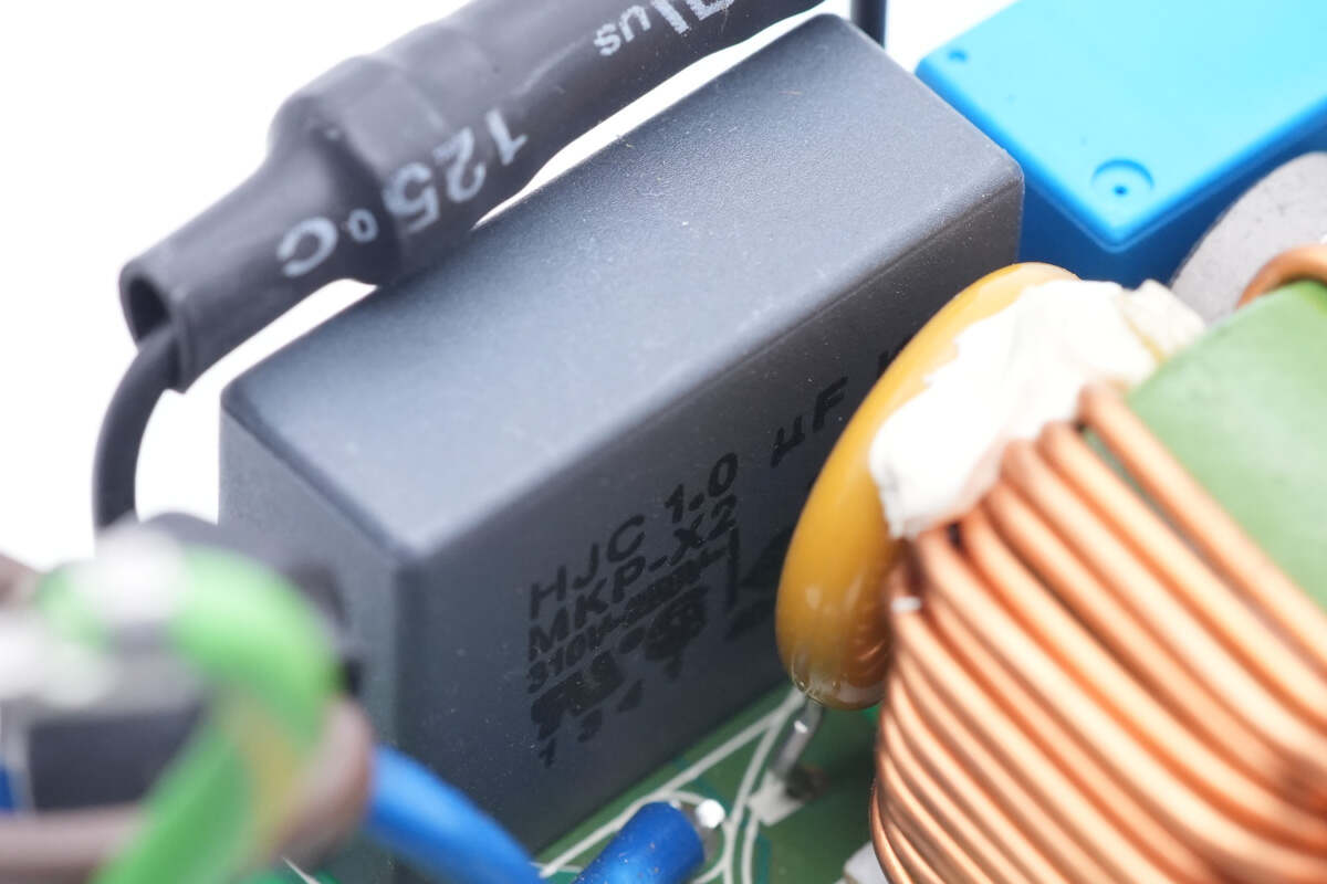
The safety X2 capacitor is from HJC. 1μF.
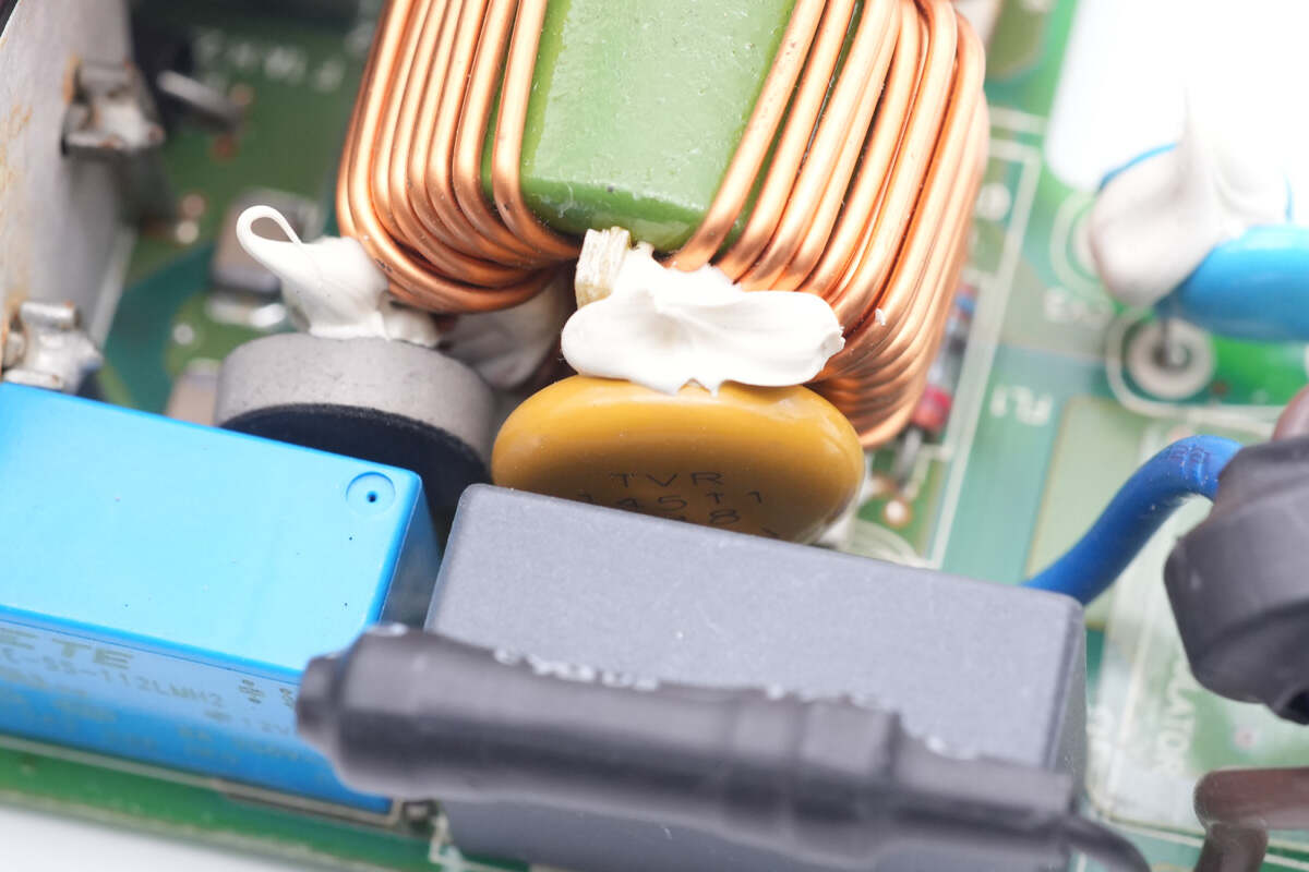
The yellow varistor is used for input surge protection. Model is TVR14511.
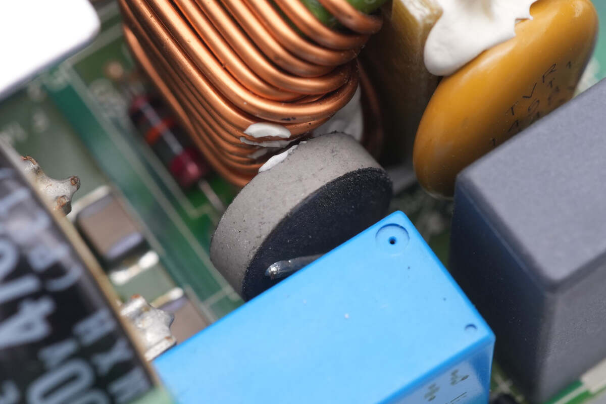
The NTC thermistor is used to limit the surge current after powering on.
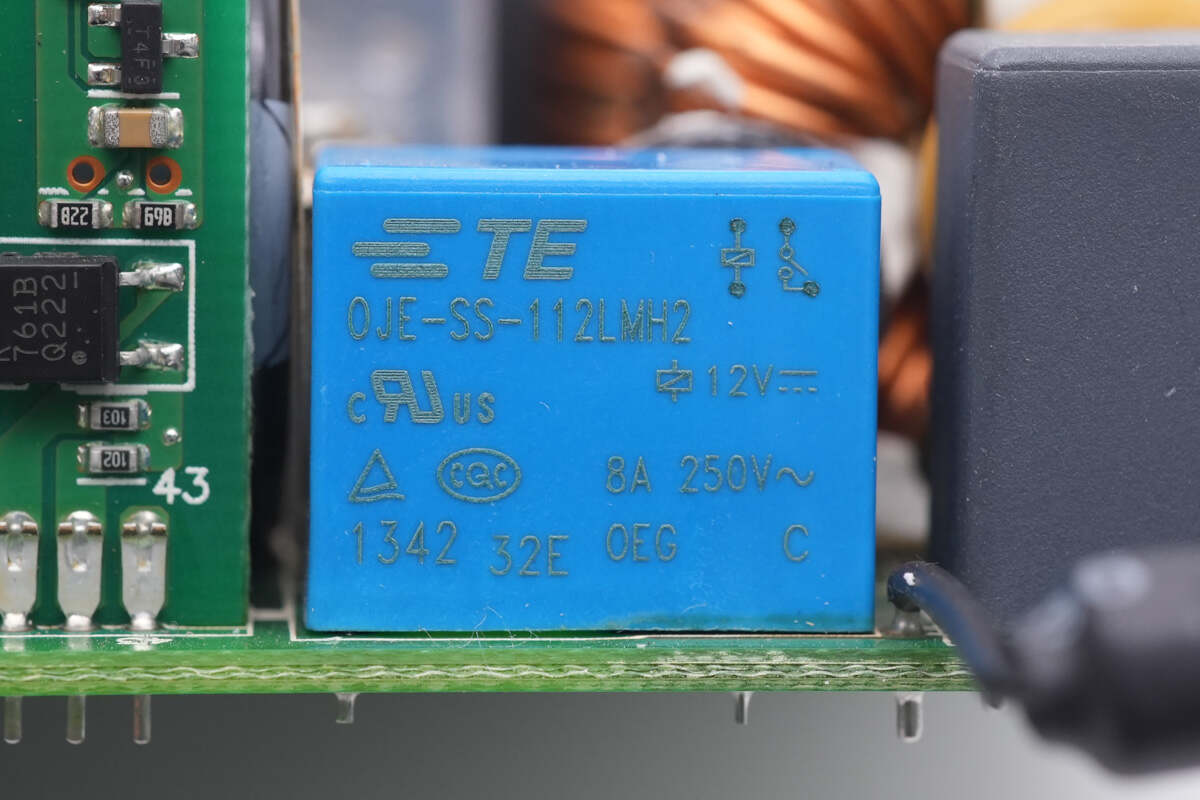
The relay is from TE. It is used to short circuit the NTC thermistor and improve power conversion efficiency. Model is 0JE-SS-112LMH2. 12V 8A.
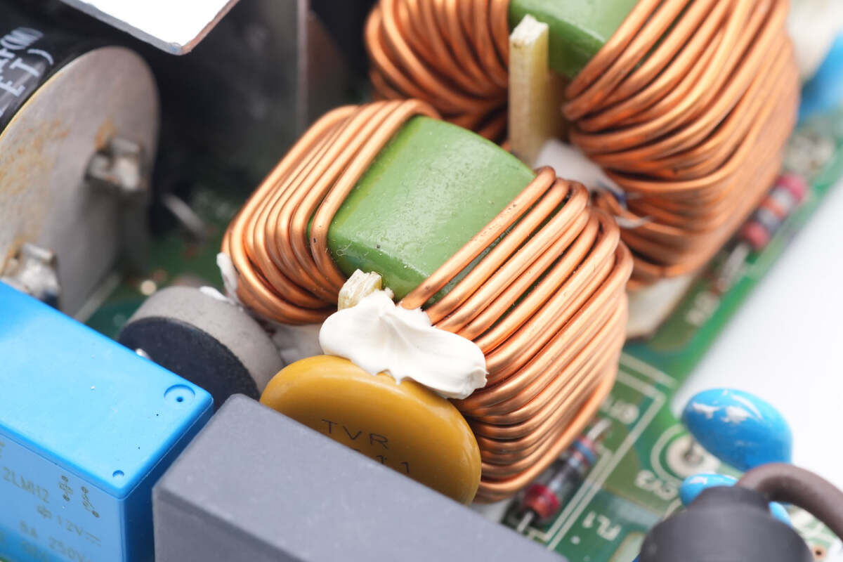
One of the common mode chokes is wound with magnet wires, and it's also insulated with bakelite.
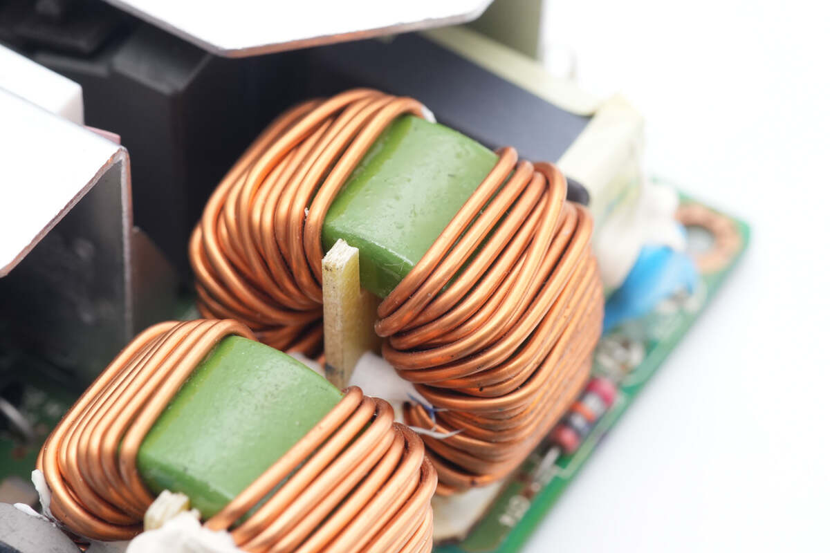
Another common mode choke is the same.
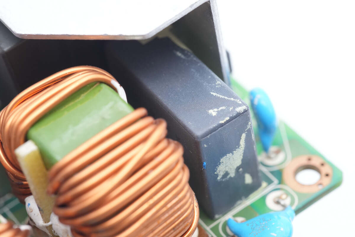
The safety X2 capacitor next to it is insulated by tape.
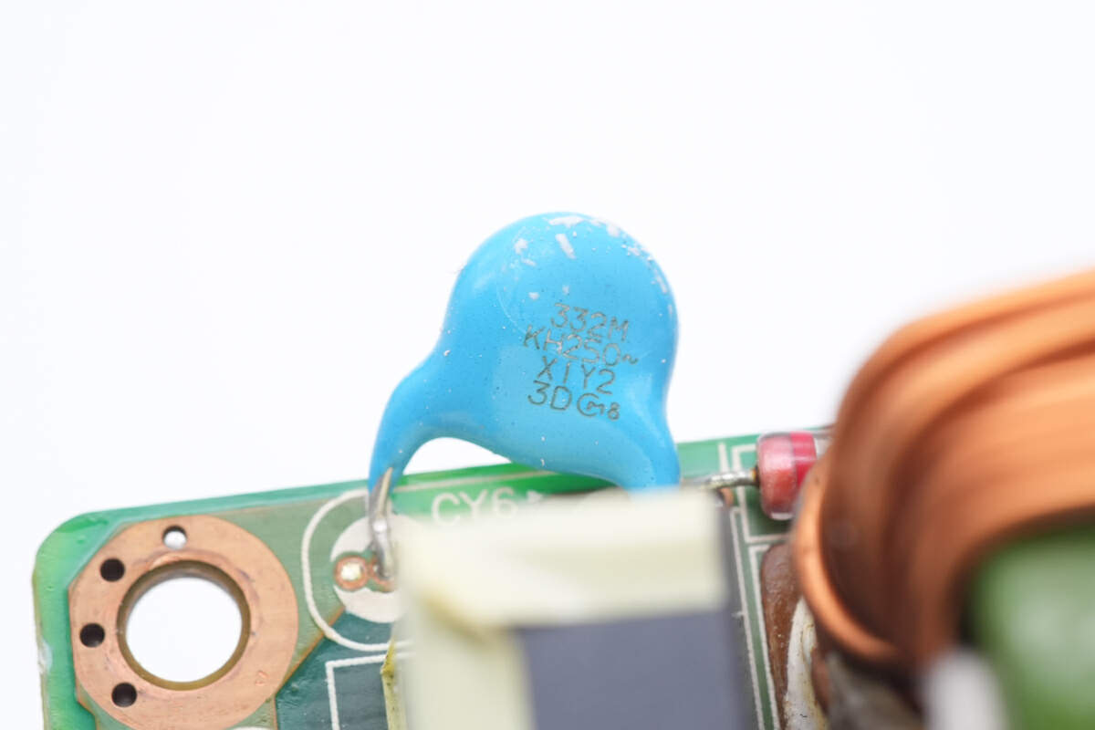
Here is one of the blue Y capacitors.
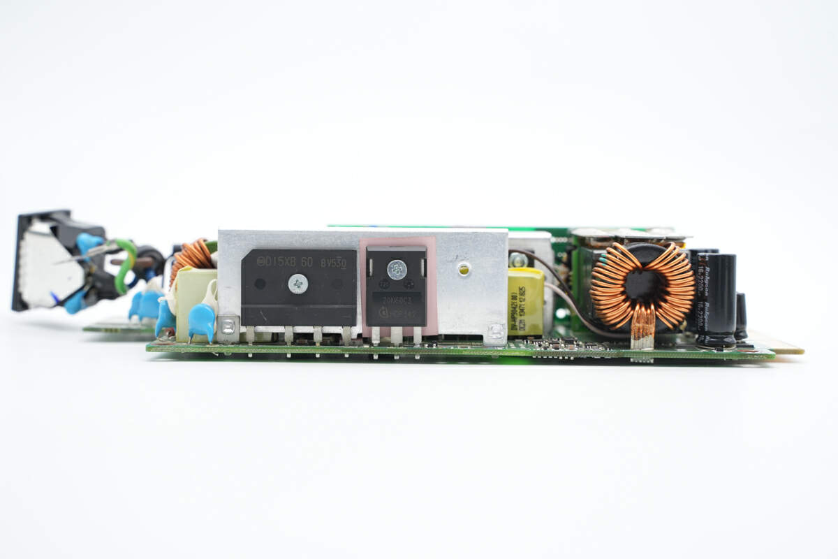
There are bridge rectifier, PFC MOSFET, filter inductor, and filter capacitor on this side of PCBA.
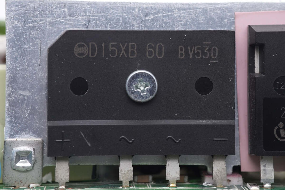
The bridge rectifier is from Shindengen. Model is D15XB60. 15A 600V.
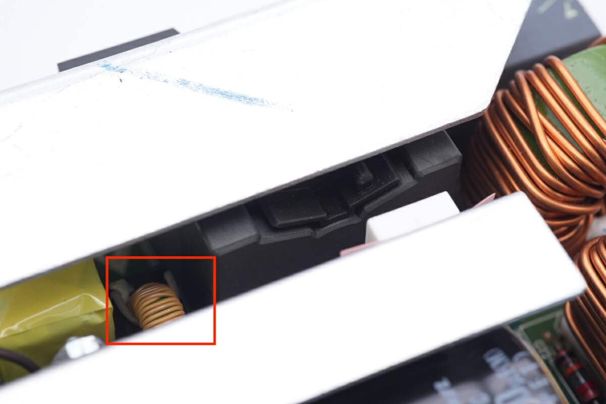
Here is the PFC boost inductor.
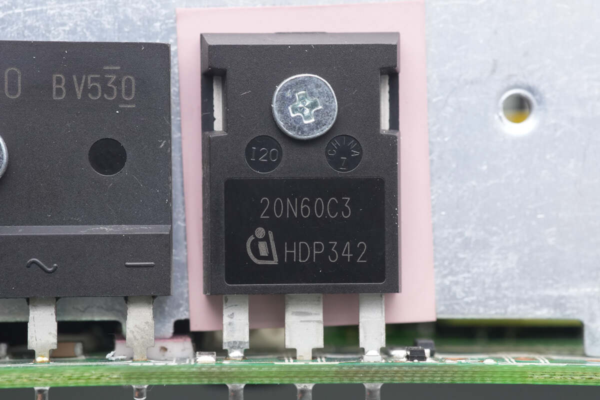
The PFC MOSFET is from Infineon and adopts TO247 package. Model is SPW20N60C3. 650V 190mΩ.
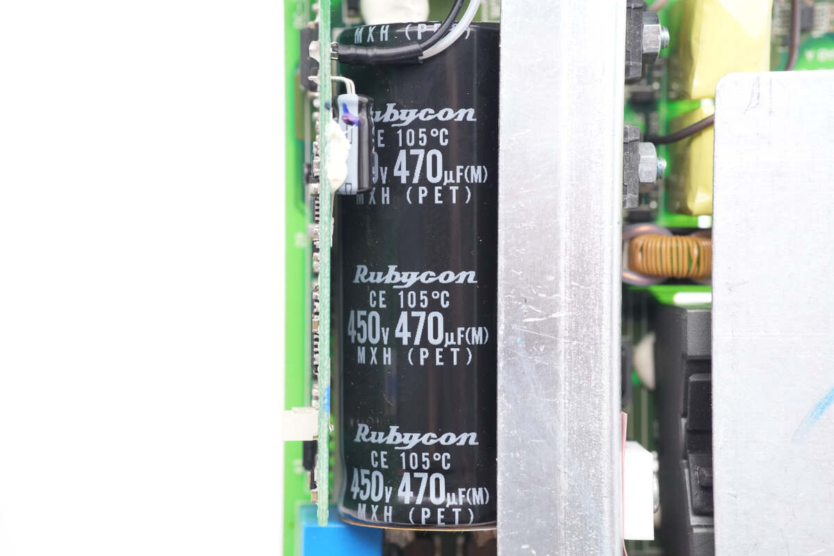
The electrolytic capacitor for input filtering is from Rubycon. 450V 470μF.
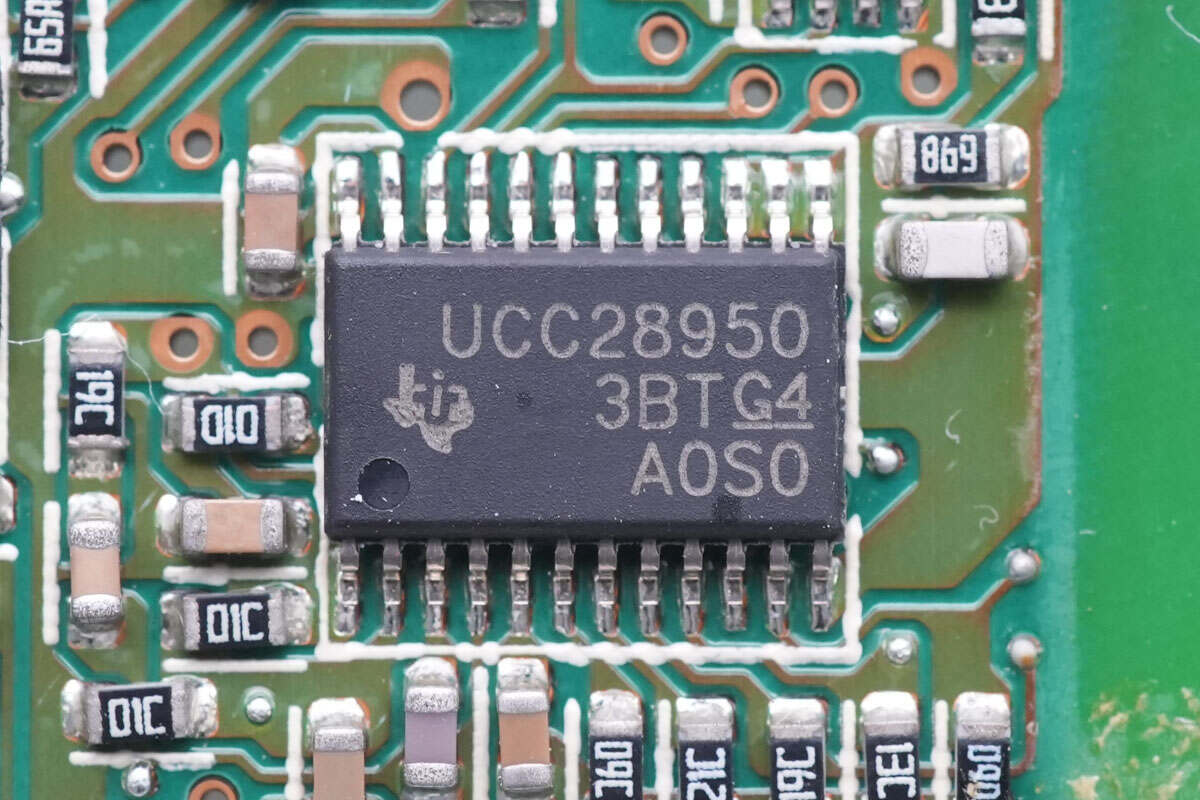
The master control chip is from TI. It's a phase-shifted full-bridge controller with synchronous rectification and enhanced wide range resonant zero voltage switching (ZVS) capability. Model is UCC28950.
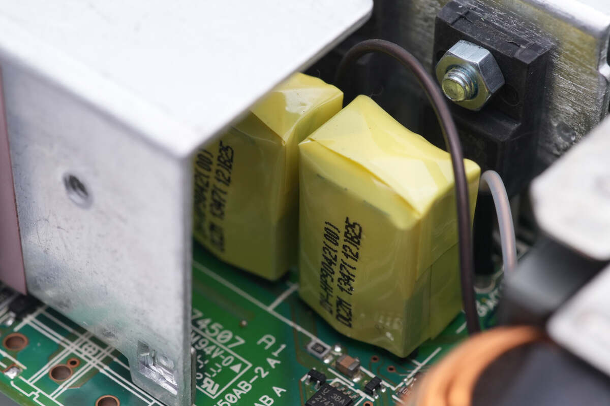
Two transformers for isolating drive are insulated by tapes.
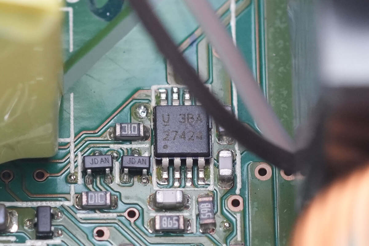
One of the drivers for transformer is also from TI. Model is UCC27424.
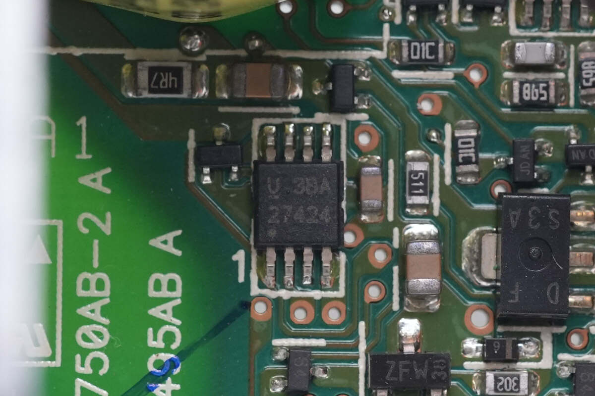
The other driver is the same as the previous one.
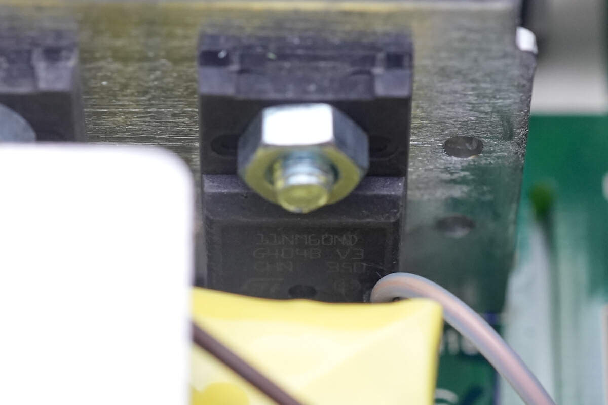
The MOSFET is from ST and adopts TO220FP package. Model is STF11NM60ND. 600V 370mΩ.

The other MOSFET is the same.
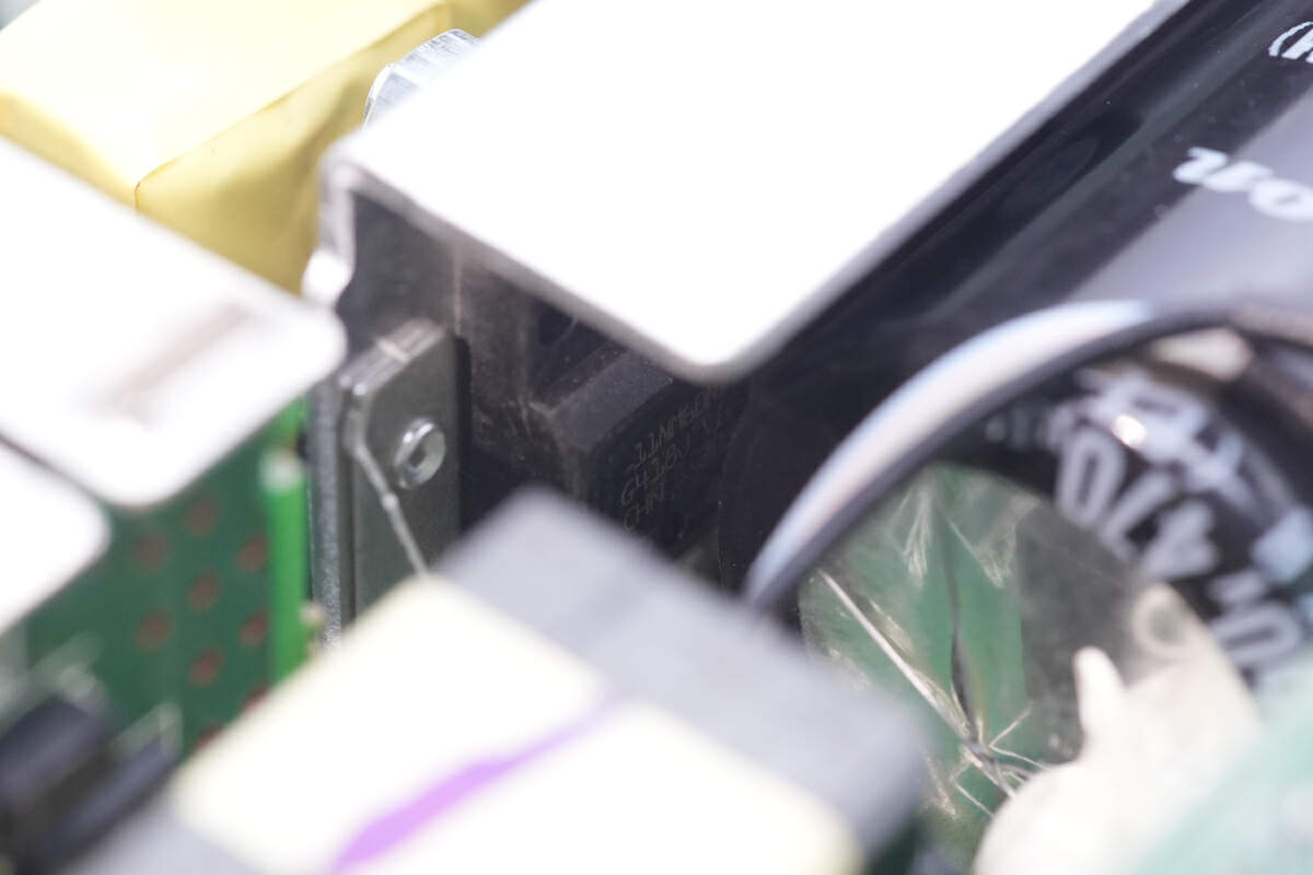
The power supply adopts a phase-shifted full-bridge design.
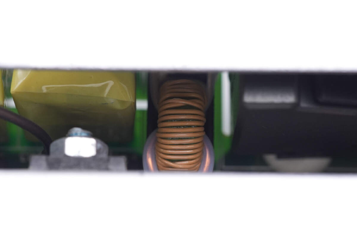
Here is one of the current transformers.
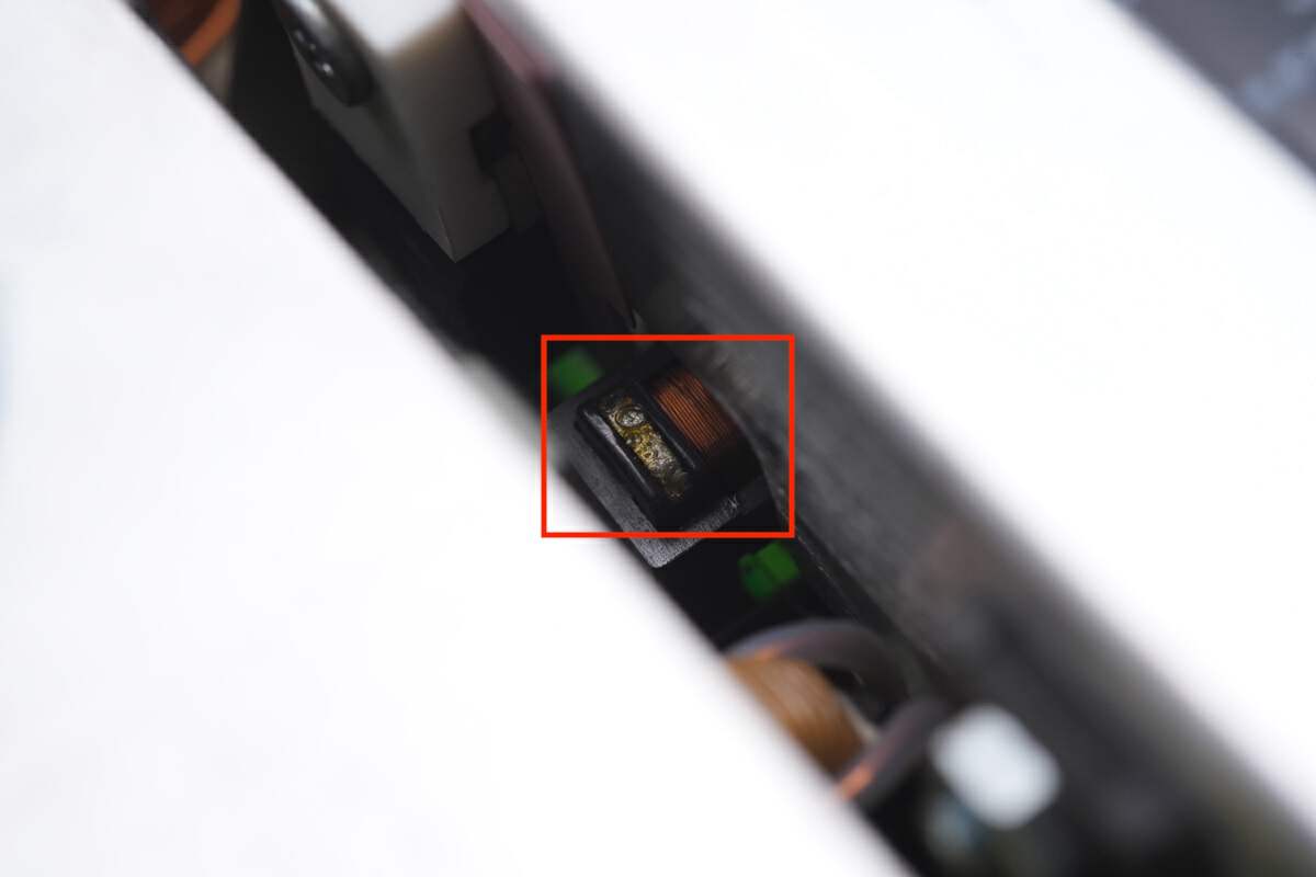
There is the other current transformer.
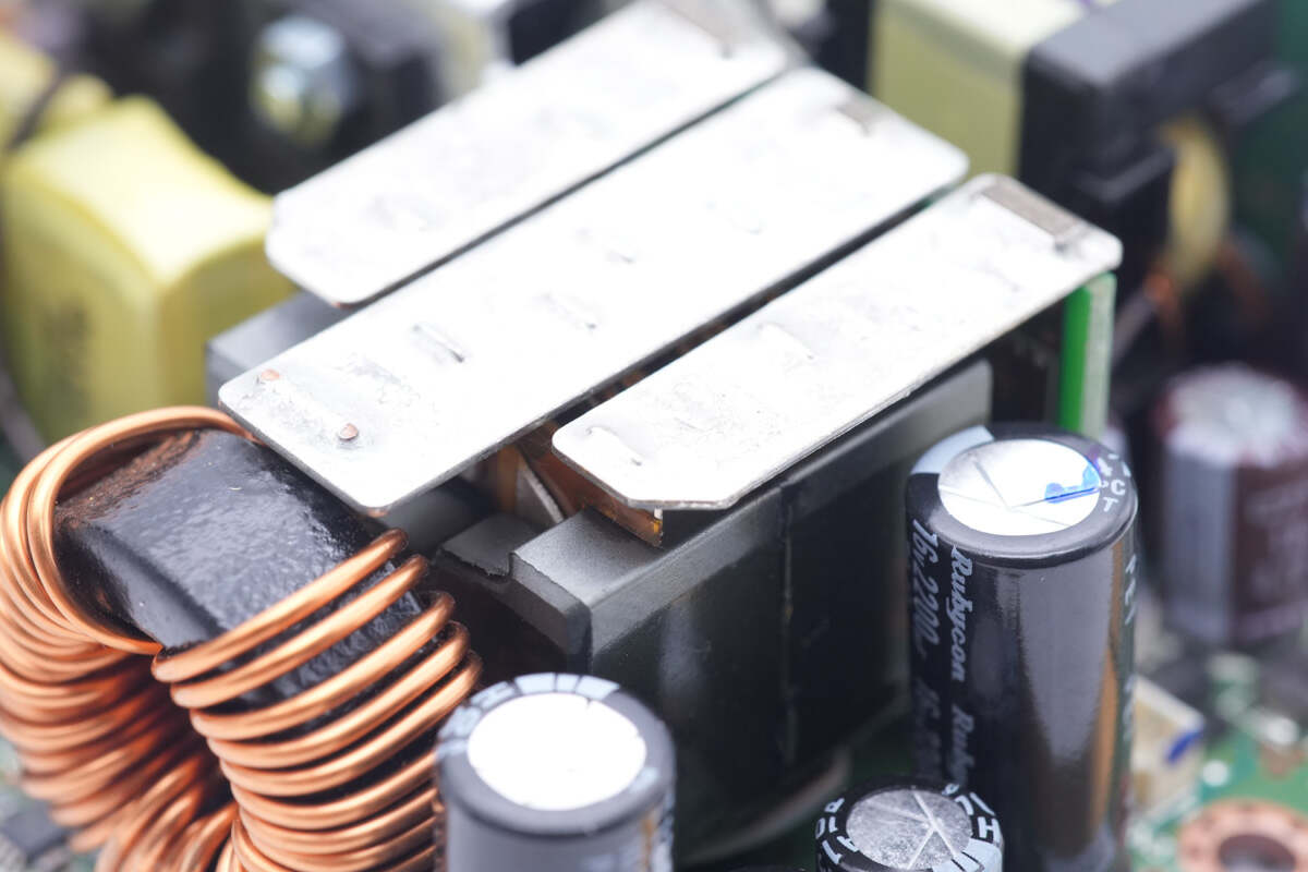
The transformers are connected to the PCBA by copper sheets.
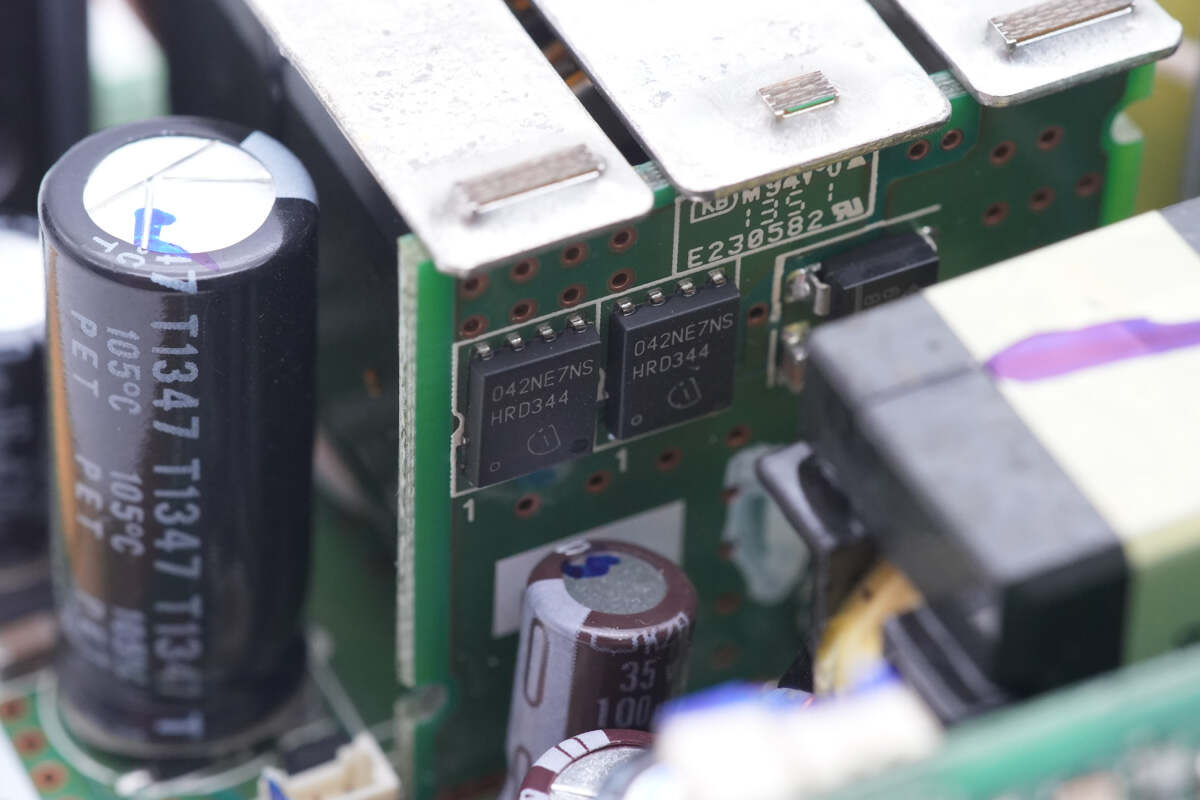
The synchronous rectifier PCB is soldered on the other side. The two MOSFETs are from Infineon and adopt PG-TDSON-8 package. Model is BSC042NE7NS3 G. 75V 4.2mΩ.
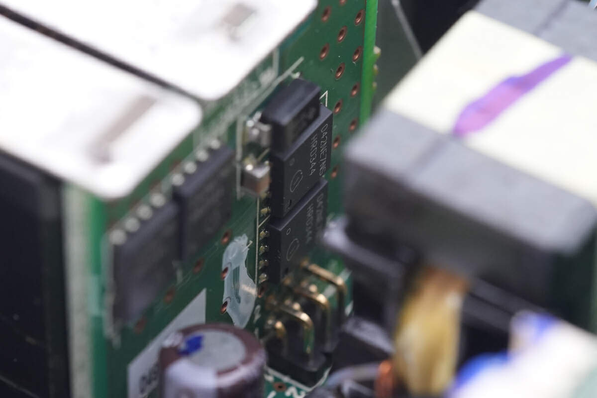
The other two MOSFETs are the same model.
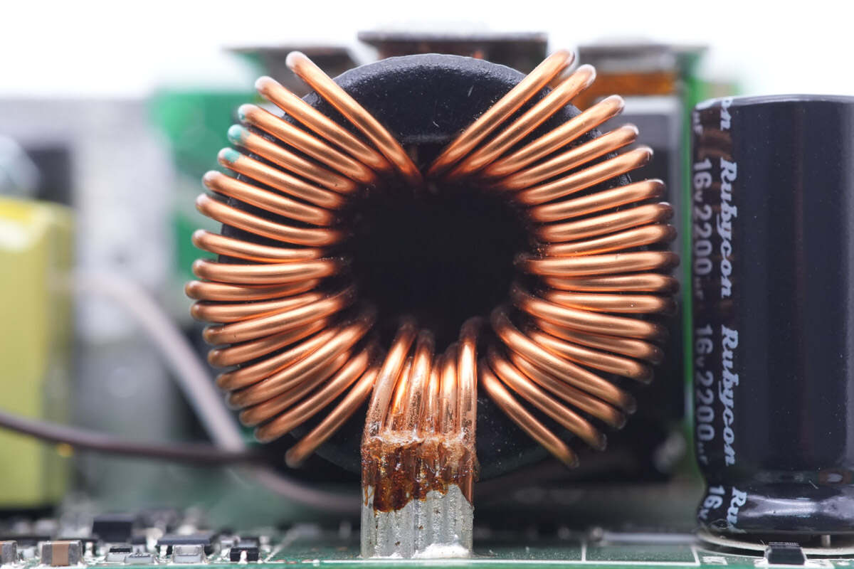
The filter inductor for output filtering is wound with magnet wires.
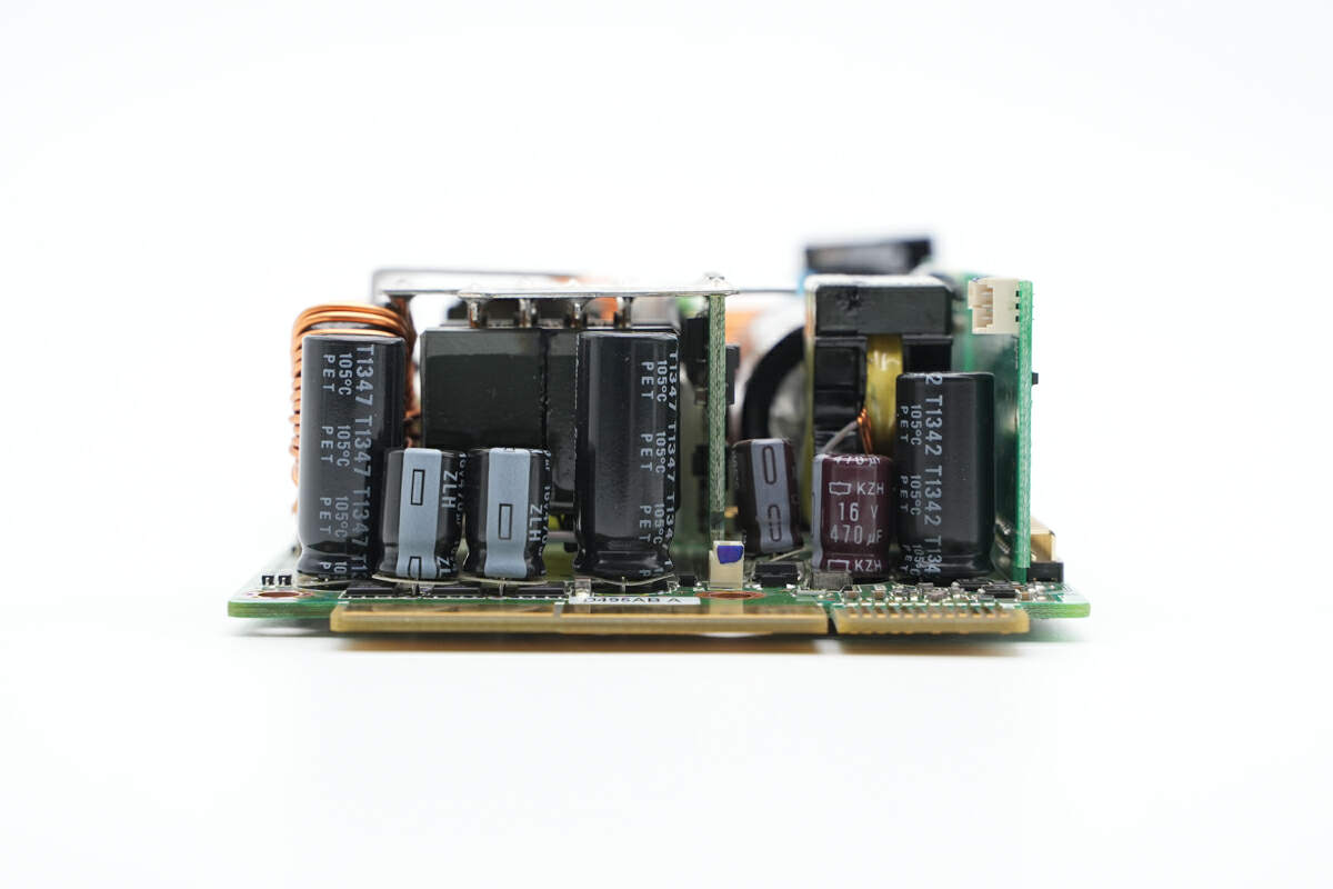
Multiple electrolytic capacitors are soldered on the output end.
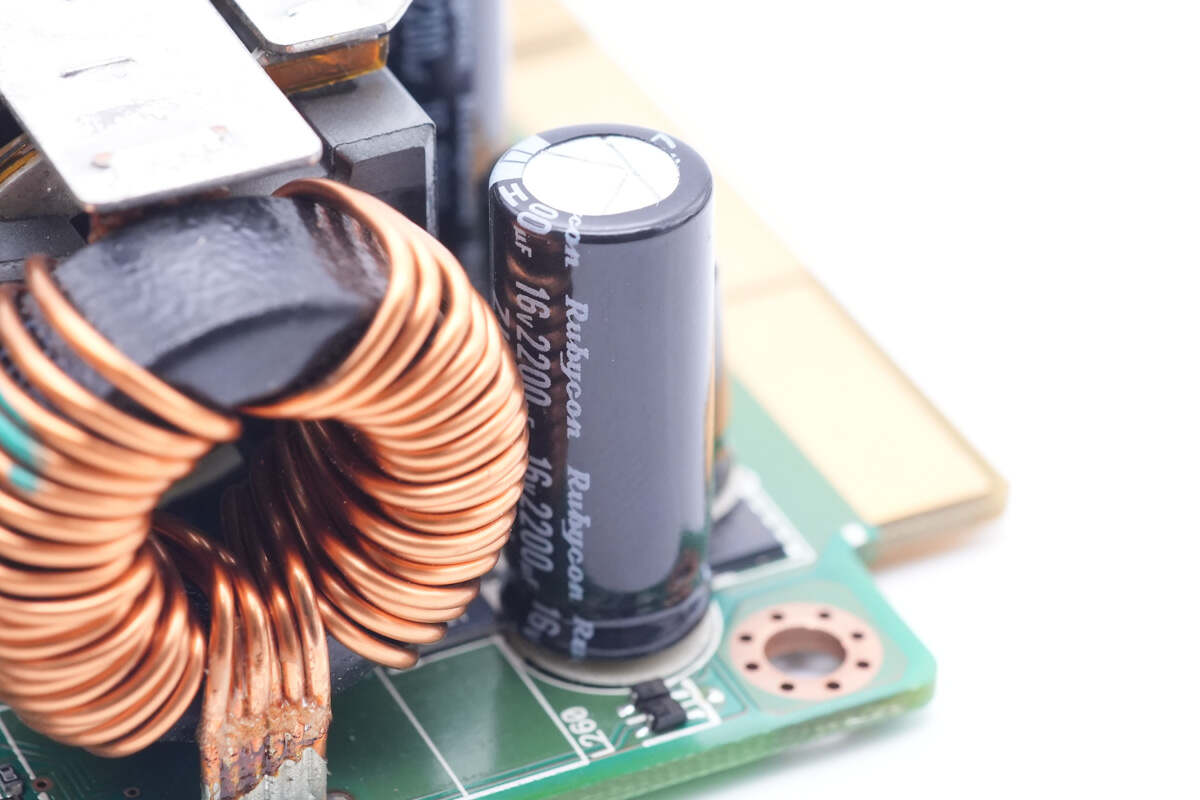
This electrolytic capacitor for output filtering is from Rubycon. 16V 2200μF.
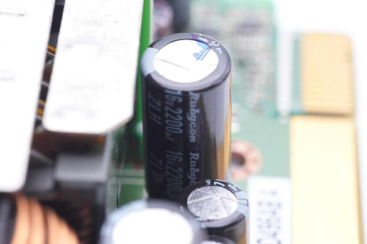
Another electrolytic capacitor is the same as the first one.
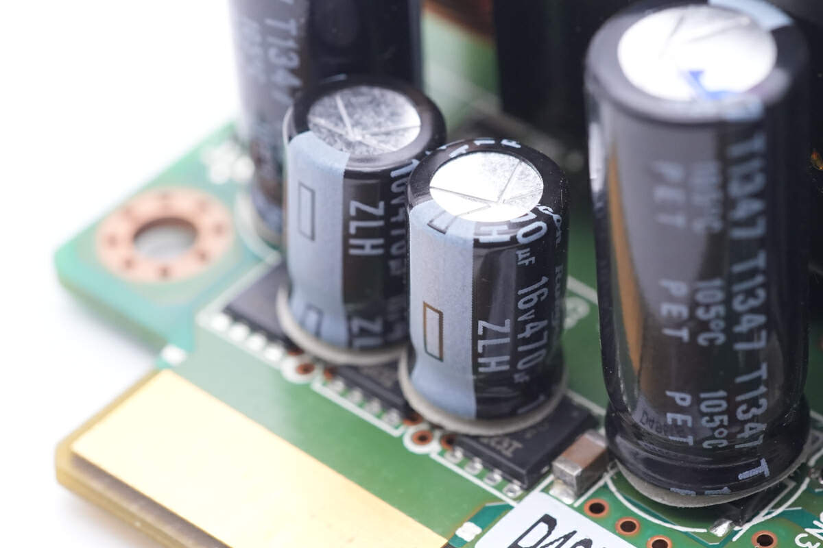
These two electrolytic capacitors are from Rubycon ZLH series. 16V 470μF.
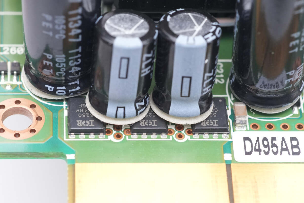
Three MOSFETs for output control are under the electrolytic capacitors.
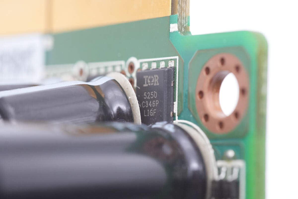
Those MOSFETs are all from Infineon and adopt PQFN5 x 6 package. Model is IRFH5250. 25V 1.15mΩ.
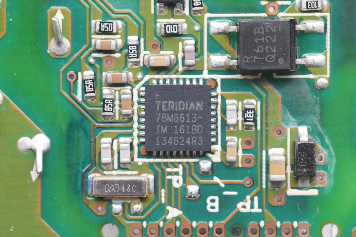
The power measurement IC is from ADI, it integrates 4 signal inputs, 22-bit ADC and 32-bit computing unit, as well as 8-bit MPU and 32KB FLASH. Model is 78M6613.
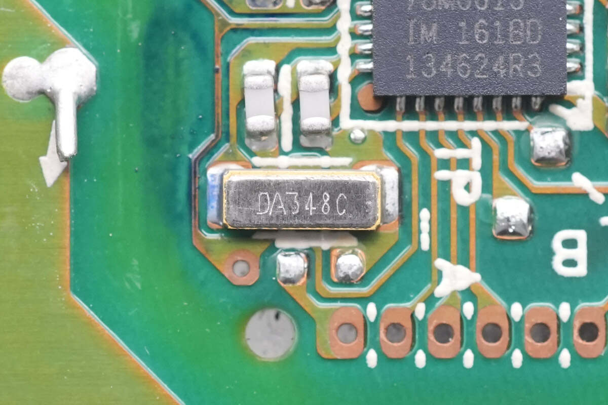
The crystal oscillator below it is 32.768kHz.
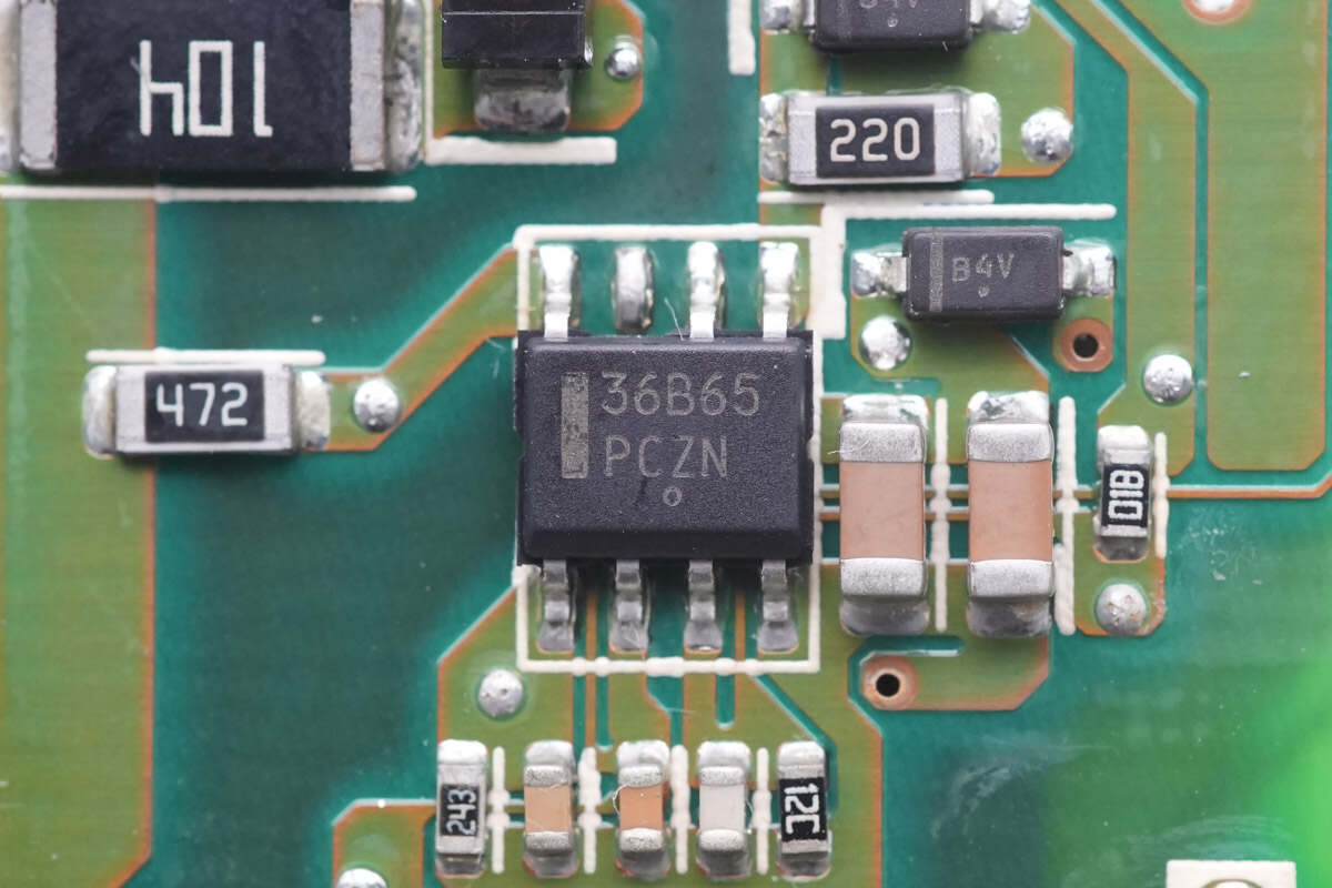
The master control chip for auxiliary power supply is from Onsemi. Model is NCP1236.
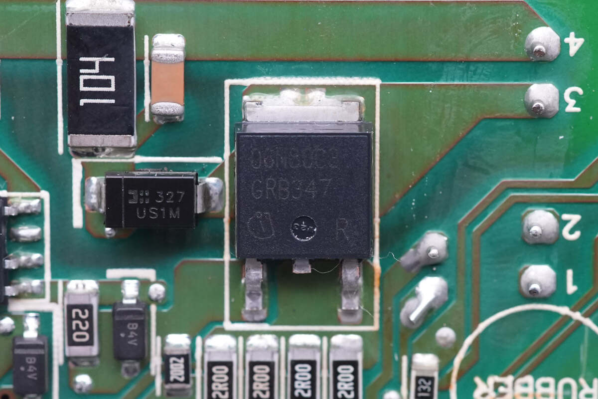
The MOSFET for auxiliary power is from Infineon and adopts TO252 package. Model is SPD06N80C3. 800V 900mΩ.
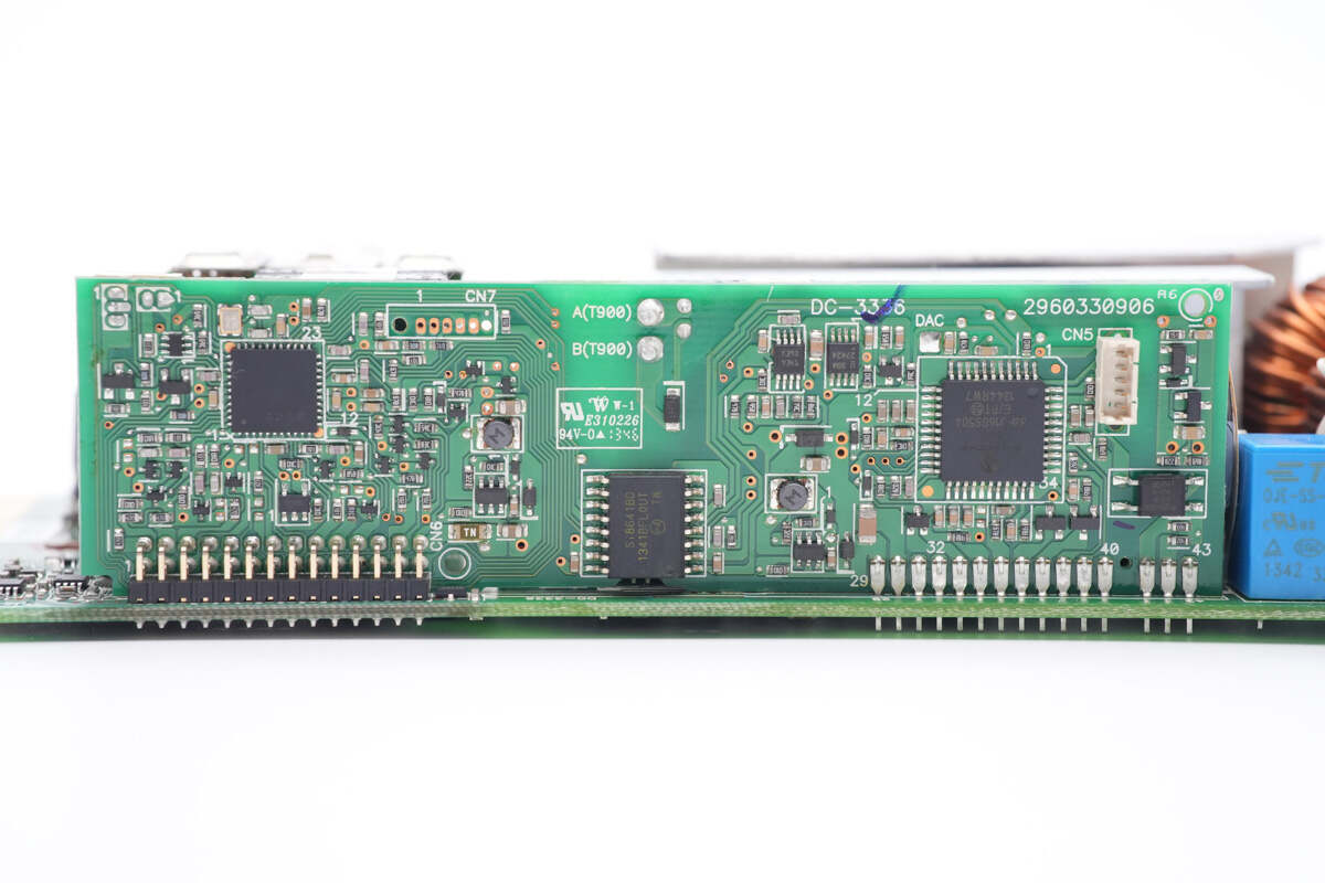
There are two MCUs and one digital isolator on the vertical PCB.
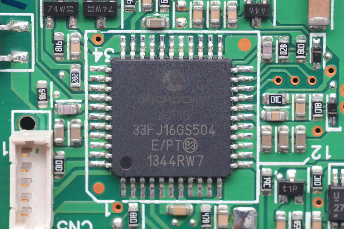
One of the MCUs is from Microchip and it is used to drive PFC MOSFET. It integrates 16-bit dsPIC33F CPU, high-speed PWM, ADC, and high-speed comparator. Model is dsPIC33FJ16GS504.
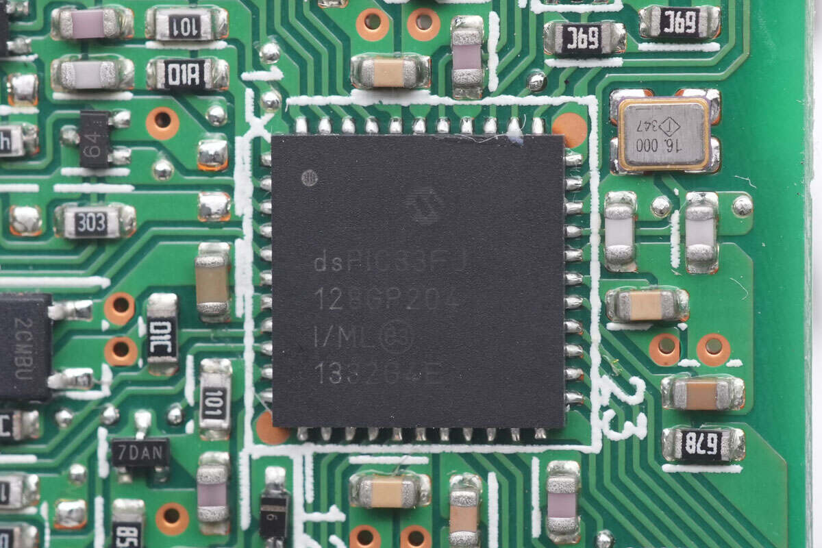
The other MCU is also from Microchip, and It integrates high-performance dsPIC33FJ core. It is used to execute digital filtering algorithms and high-speed precision digital control loops. Model is dsPIC33FJ128GP204.
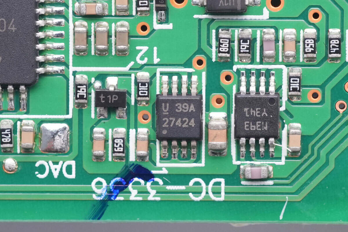
The TI UCC27424 is used to drive PFC MOSFET.
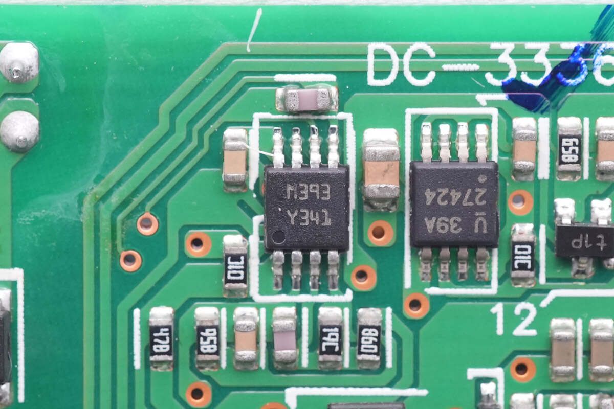
The dual voltage comparator is used for signal detection. Model is LM393.
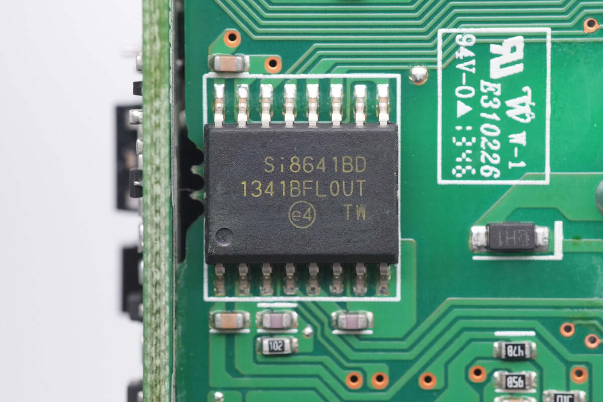
The low-power quad channel digital isolator is from Skyworks, and it has a transfer speed of 150Mbps. Model is Si8641BD.
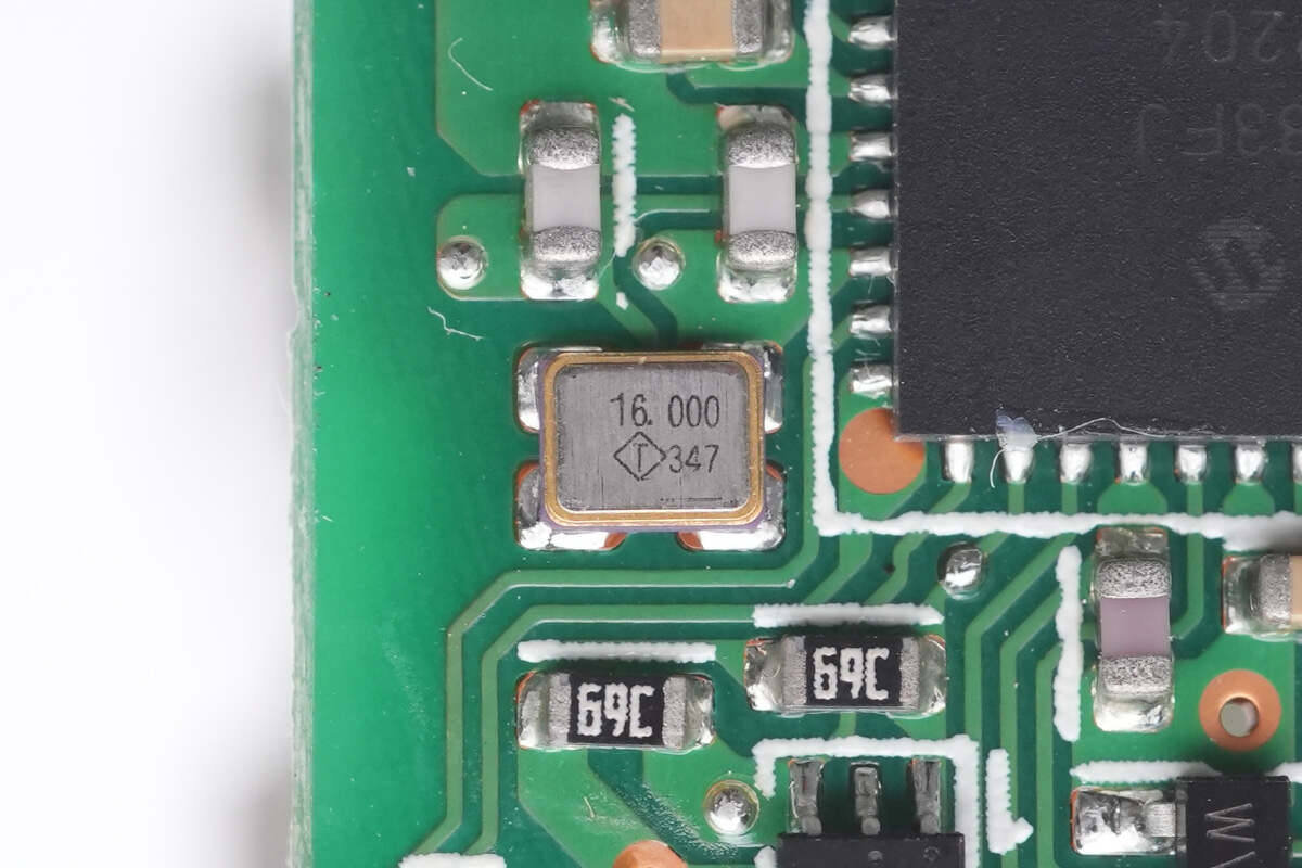
This is the external 16.000MHz crystal oscillator.
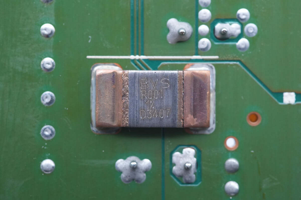
The sampling resistor is used to detect the output current. 1mΩ.
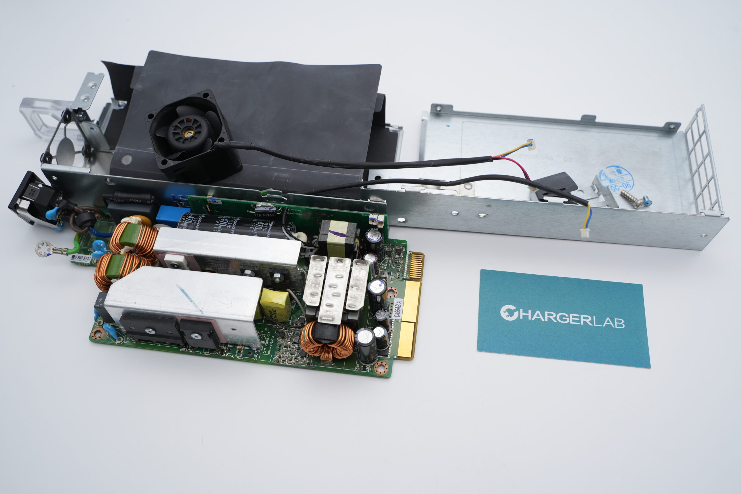
Well, those are all components of this server power supply.
Summary of ChargerLAB
The Dell 495W server power supply supports an output of 12V 41.25A. And it also passed 80 PLUS Platinum standard.
Its manufacturer is Delta. And it adopts two MCUs from Microchip. The two master control chips are from TI and Onsemi. Most of the other components are also from well-known manufacturers such as Infineon, Rubycon, and Skyworks.
The components are compactly laid out and the space utilization is excellent. All of which makes its build quality solid.
Related Articles:
1. Teardown of DELL 165W PD3.1 GaN Power Adapter (LA165PM210)
2. Teardown of ASUS ROG Thor 1600W Titanium Power Supply
3. Teardown of 372W Power Supply (For SONY PlayStation 5)

