Introduction
On June 6, 2023, Apple released an unimaginable product at WWDC 2023 that is expected to change the future completely: Apple Vision Pro. As a revolutionary product that opens the era of spatial computing, it has a futuristic and technological appearance and integrates a variety of cutting-edge technologies. Featuring groundbreaking design elements such as a high-resolution display with 23 million pixels spread across two screens and a custom Apple chip with a unique dual-chip design, the Vision Pro promises users an unparalleled immersive experience.
In order to reduce the discomfort of users when wearing it, the Vision Pro and the battery are designed to be separated. The battery is similar to a portable power bank. You can charge the battery via the USB-C port, and there's a dedicated cable for connecting to the Apple Vision Pro.

The battery comes with a 1.2-meter woven power cable, which is detachable. And it connects to the Vision Pro through a dedicated connector. The output power of the battery is 78W. It has a capacity of 35.9Wh. It supports an input voltage of 5-20.3V and a maximum input current of 3.3A. The measured maximum charging input power is about 50W.
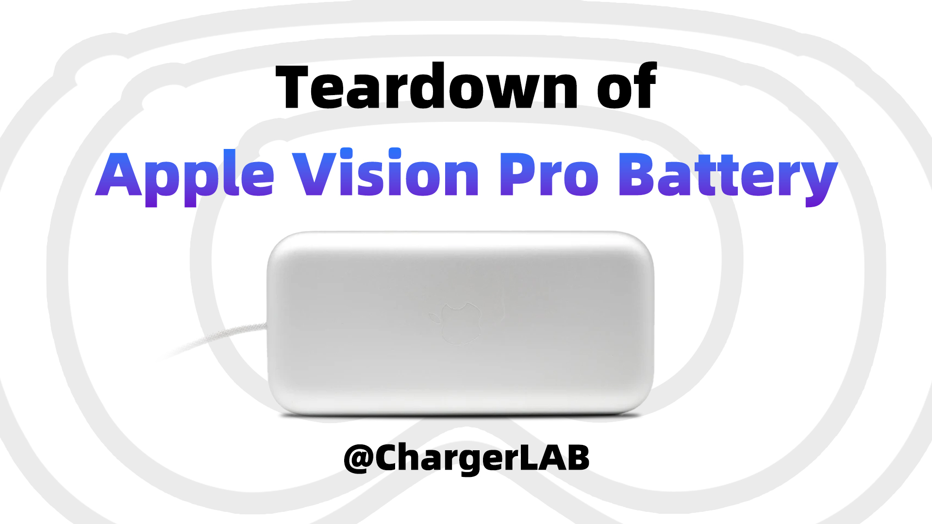
ChargerLAB recently conducted a test on the compatibility of the Apple Vision Pro Battery. This time, we are going to take it apart to see its internal components and structure.
Product Appearance
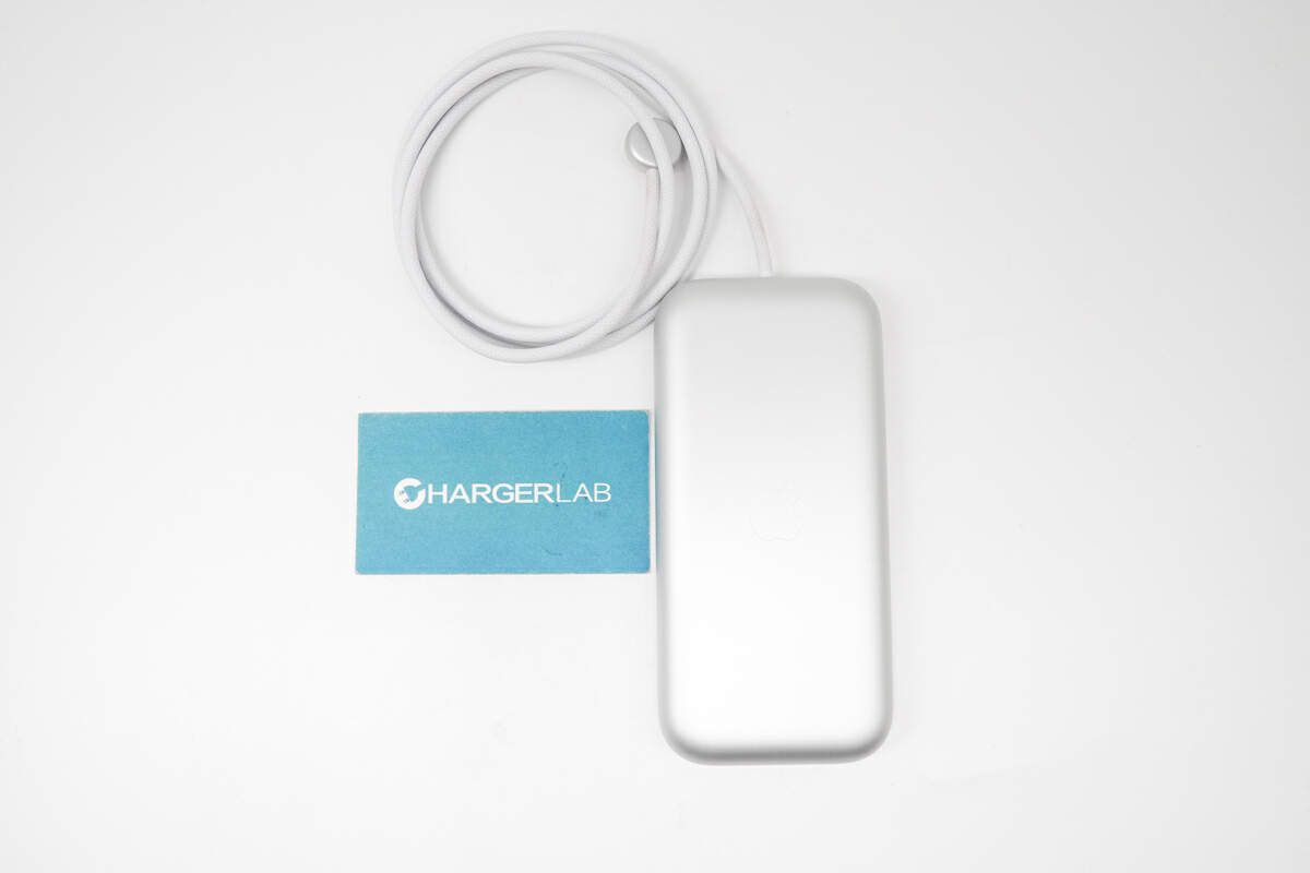
The Apple Vision Pro Battery is made out of smooth, machined aluminum and comes with a woven power cable.
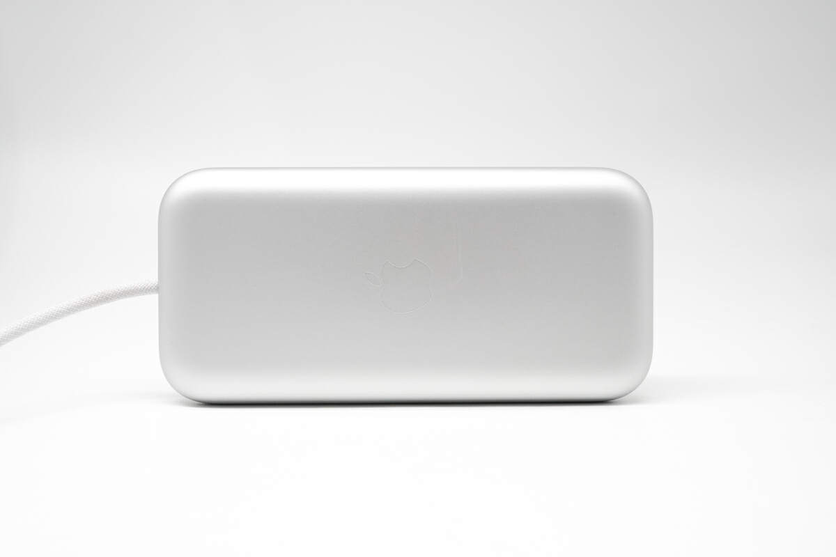
The Apple logo is embossed in the middle.
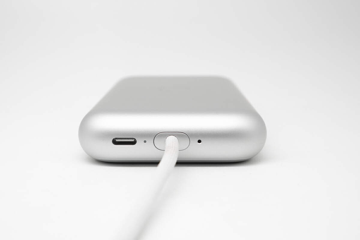
From left to right, there is a USB-C port, a small hole for removing the connector, a connector for Vision Pro, and an indicator light to show the charging status.
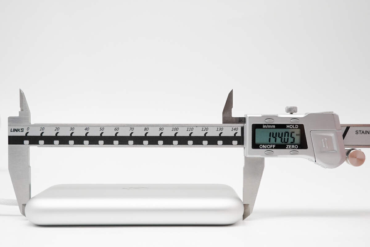
The length of it is about 144 mm (5.67 inches).
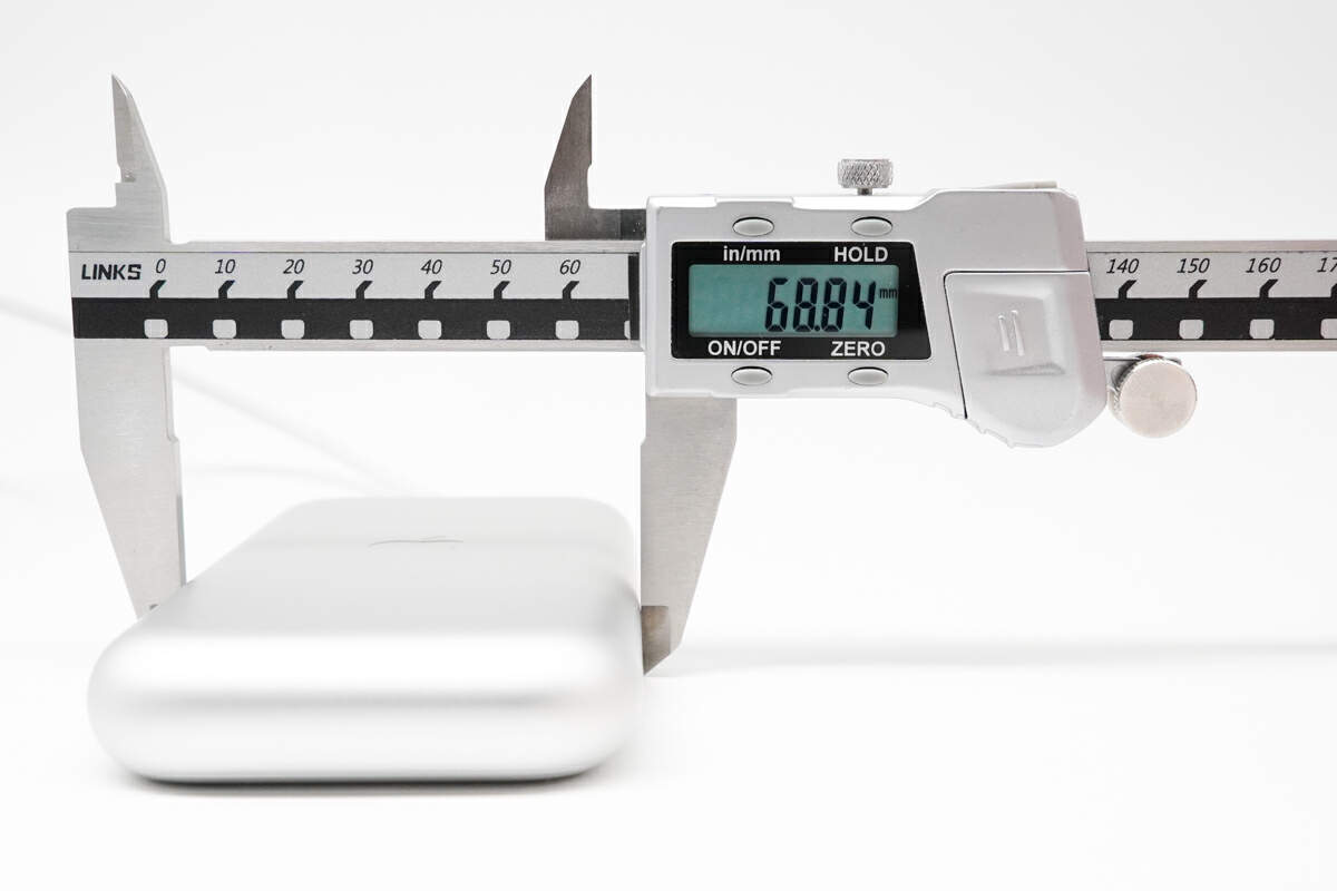
The width is about 69 mm (2.72 inches).
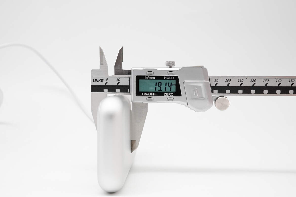
The thickness is about 19 mm (0.75 inches).
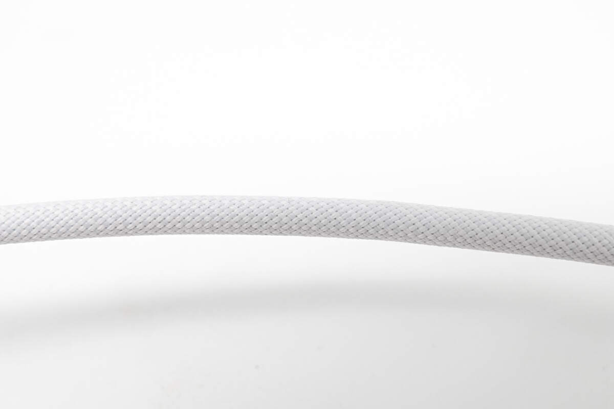
The cable is made with a woven design.
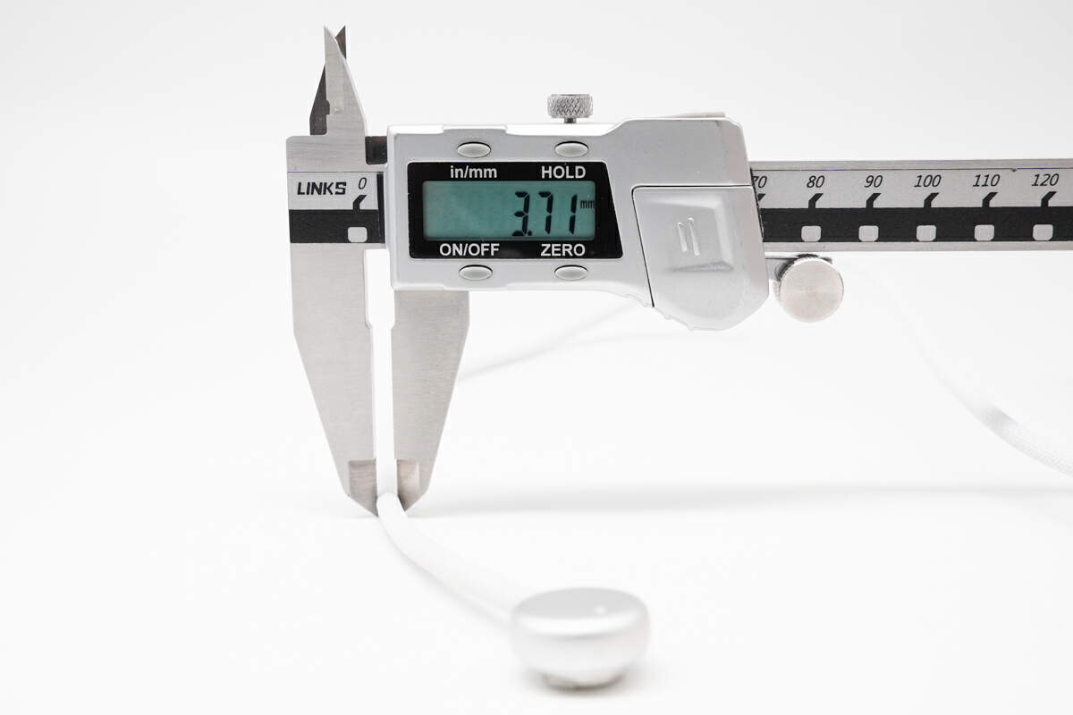
The diameter of the cable is about 3.7 mm (0.15 inches).
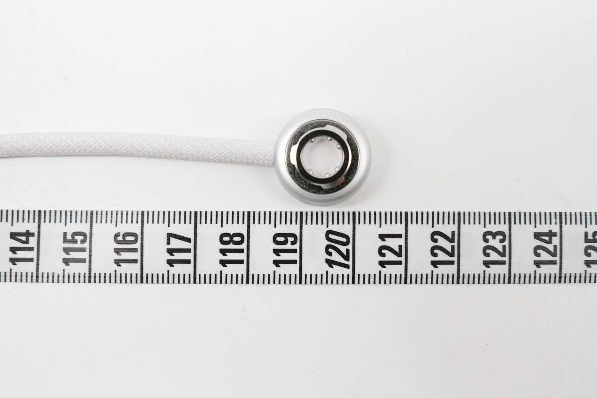
The length of it is about 120 cm (47.24 inches).

There is a positioning mark on the plug.

There are communication terminals inside the plug.
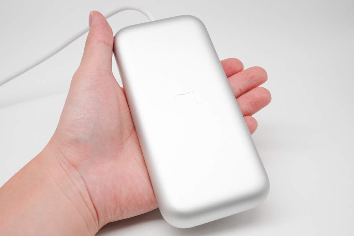
That's how big it is in the hand.
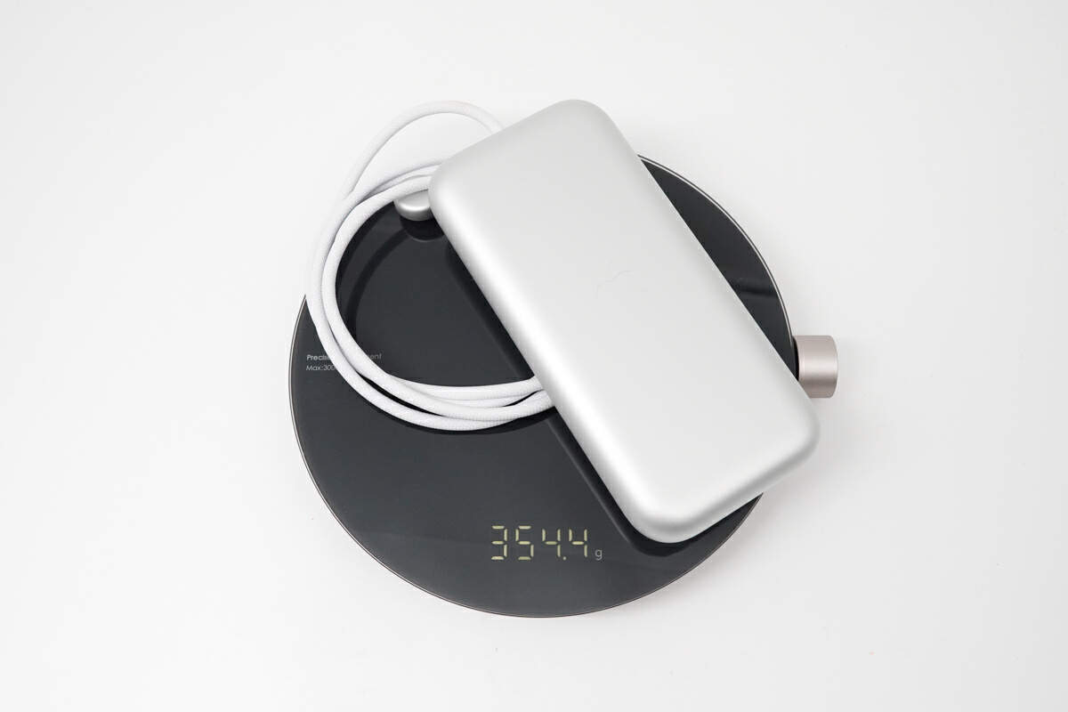
The weight is about 354 g (12.49 oz).
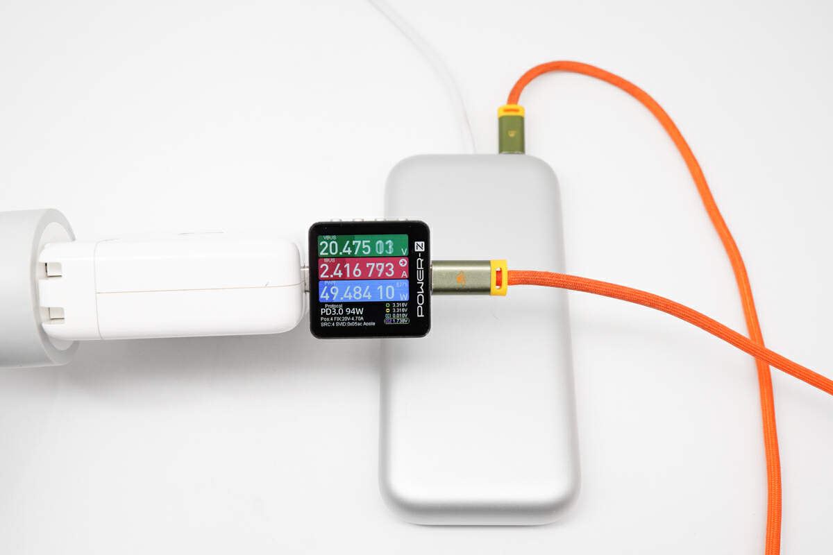
The ChargerLAB POWER-Z KM003C shows it has an input voltage of 20.5V and a current of 2.4A, and the power is about 49.5W.
Teardown
Next, let's start to take it apart to see its internal components and structure.
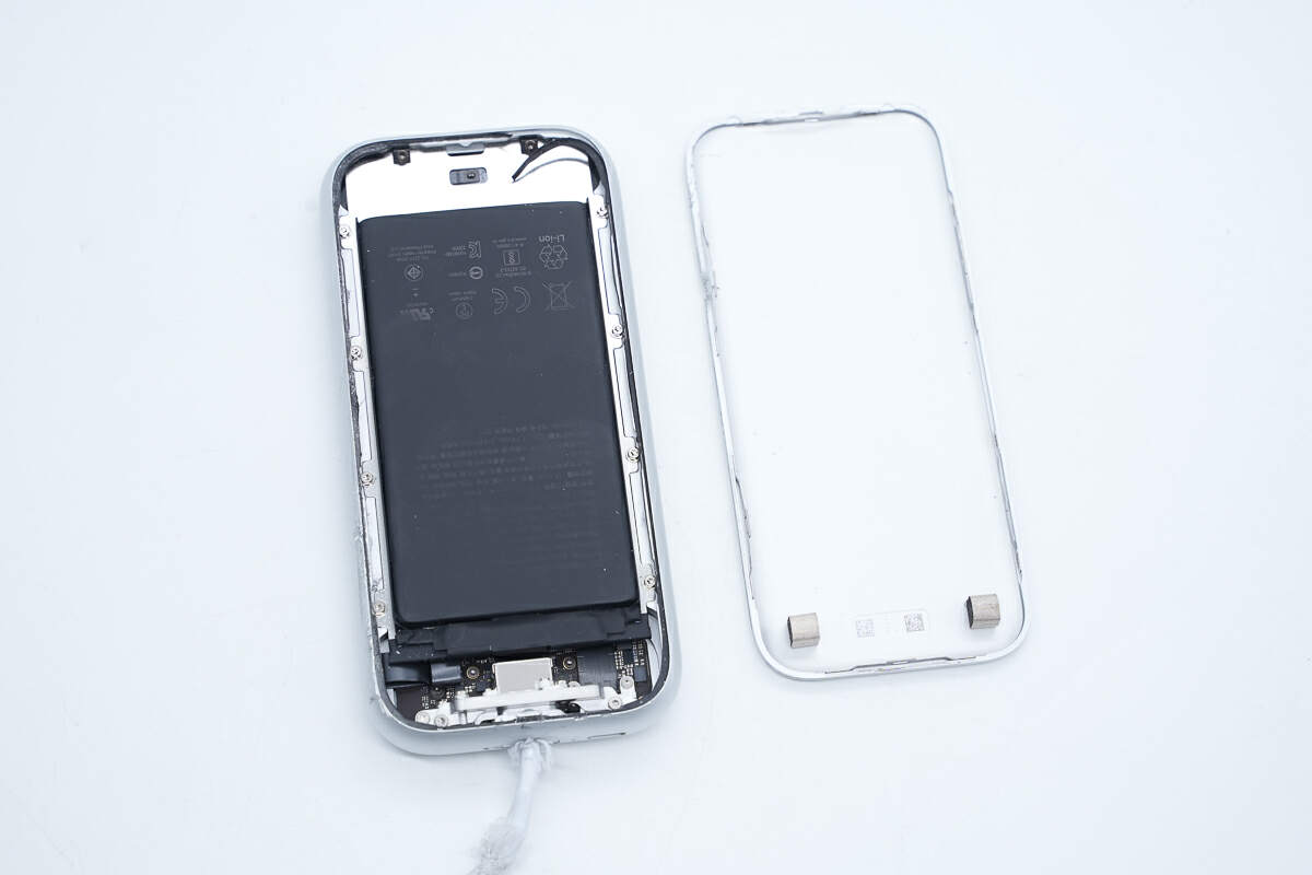
First, pry open the case along the gap. The cover is fixed with tape.
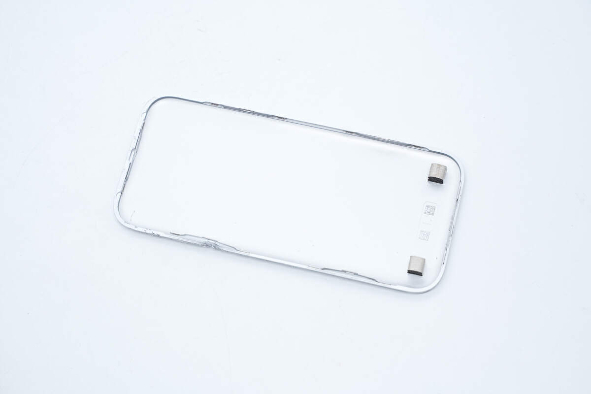
Two pieces of conductive cloth are pasted on the inside of the cover at positions corresponding to the internal metal plate for grounding.
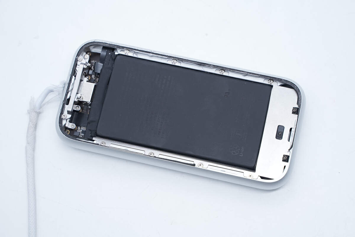
The battery is glued inside the case, and the metal plate is fixed inside the case with screws.
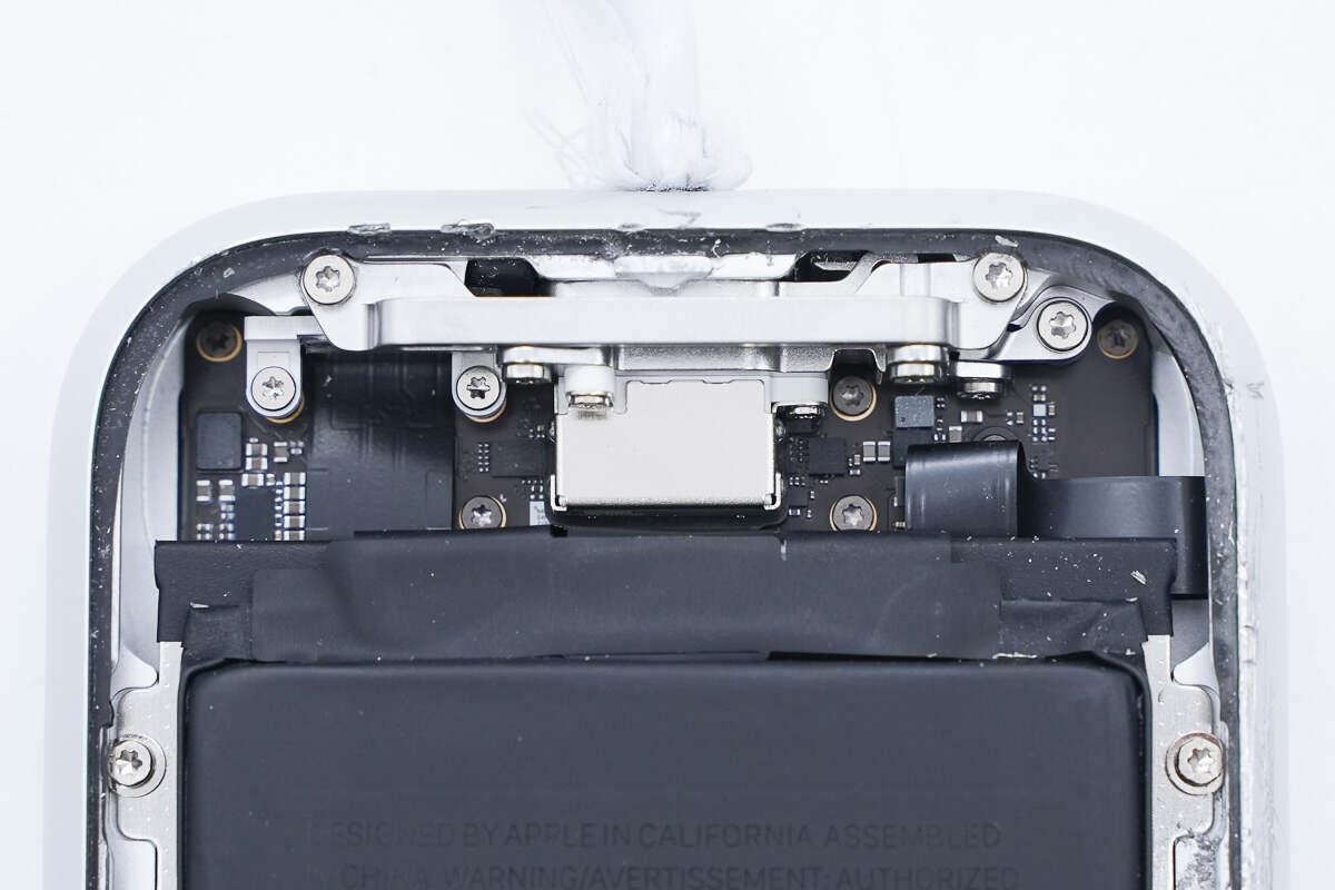
The connector is fixed inside the case by screws.
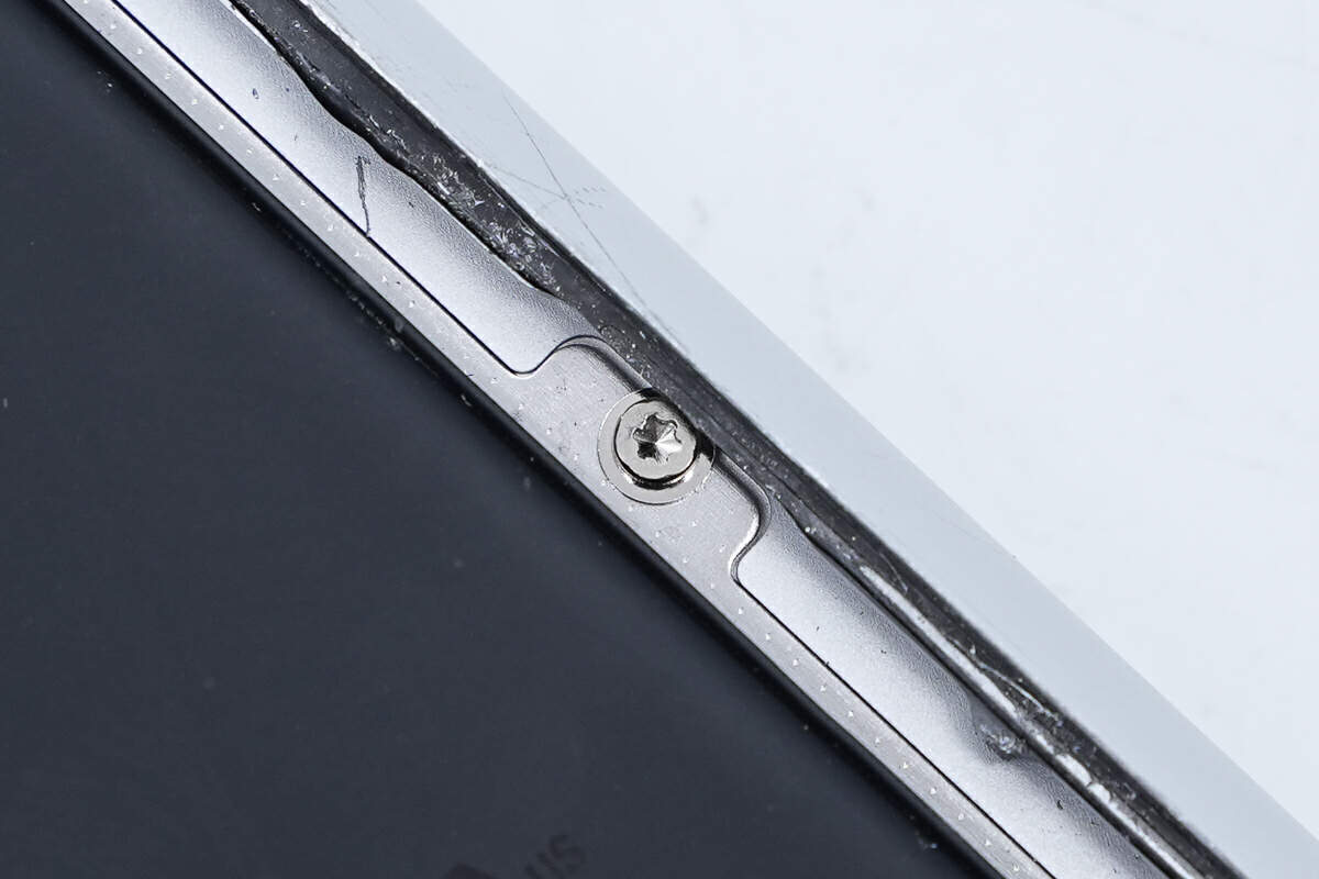
The metal plate is fixed inside the case with screws.
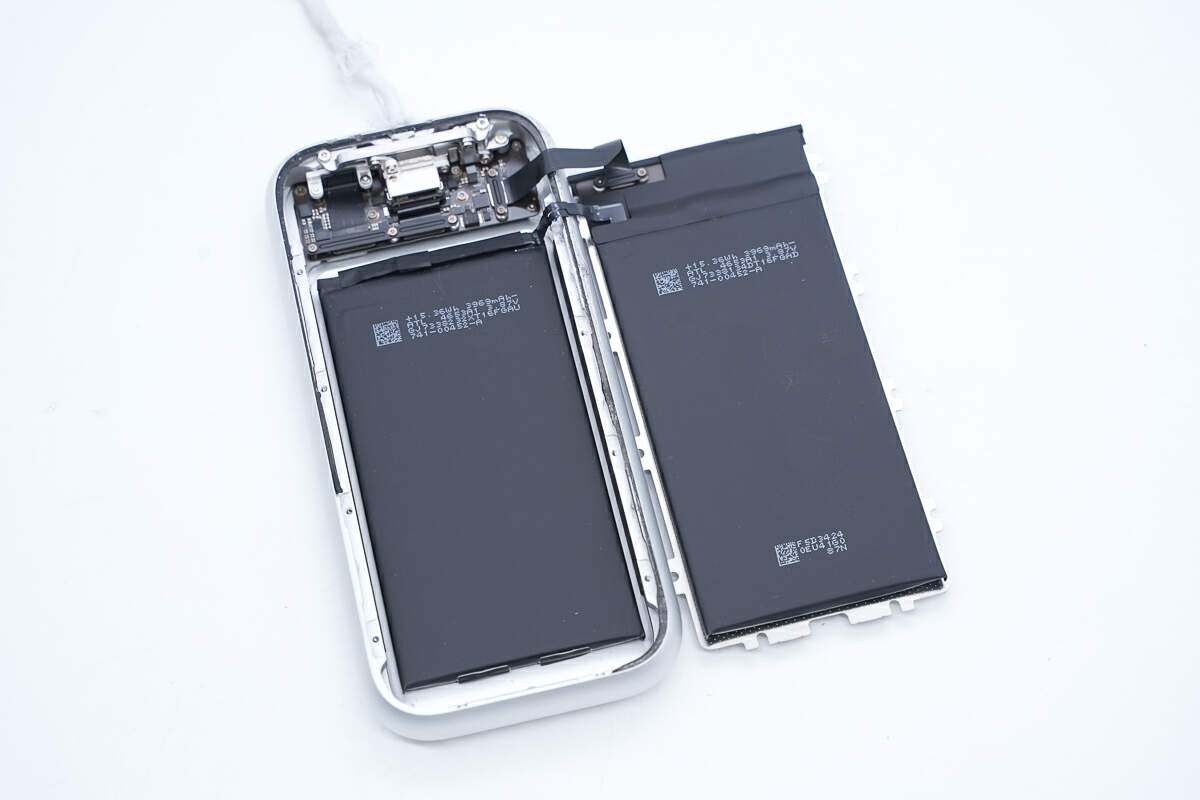
After unscrewing the screws and opening the metal plate, there is a battery protection PCB on the back of the metal plate. The battery protection PCB is connected to the PCBA module via a cable. Batteries are attached to both sides of the metal plate, and another battery is attached to the inside of the case.
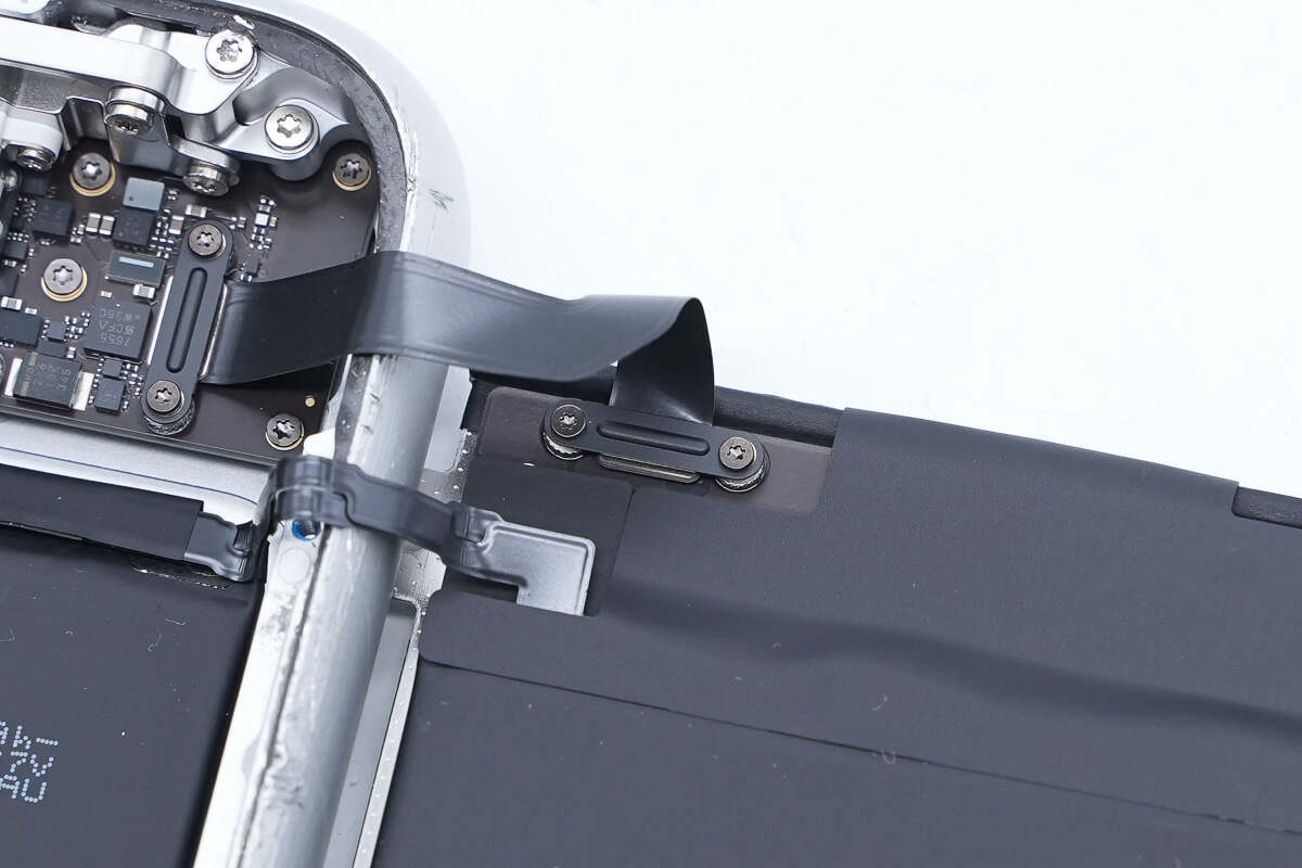
One end of the cable is fixed with screws.
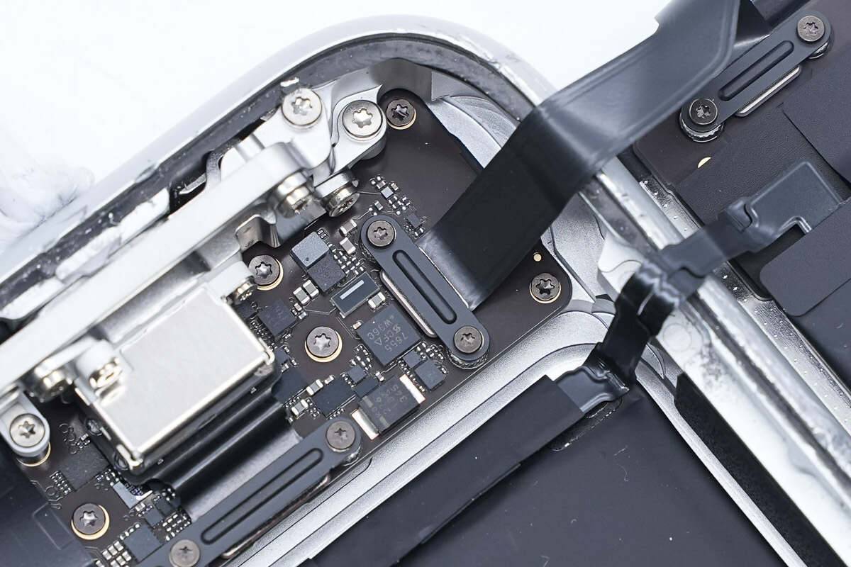
The other end of the cable is also fixed with screws.
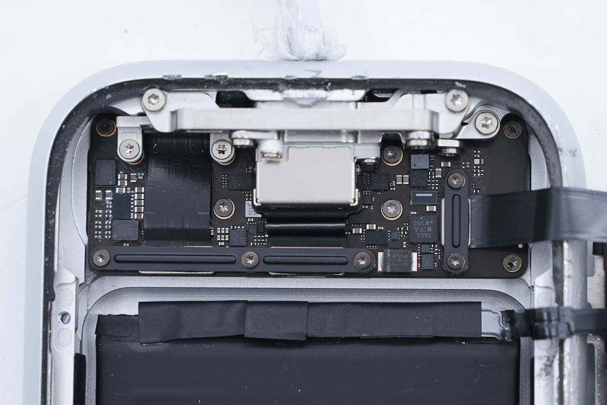
The USB-C port and output port are both on the PCBA module.
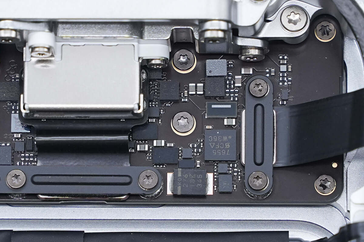
The PCBA module is fixed to the case with screws.
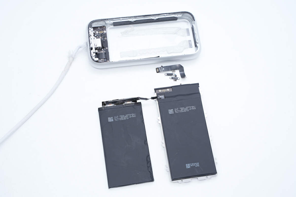
Take the battery pack out of the case and disconnect the battery pack from the PCBA module.
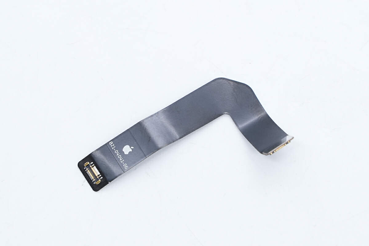
This is the cable used for the connection.
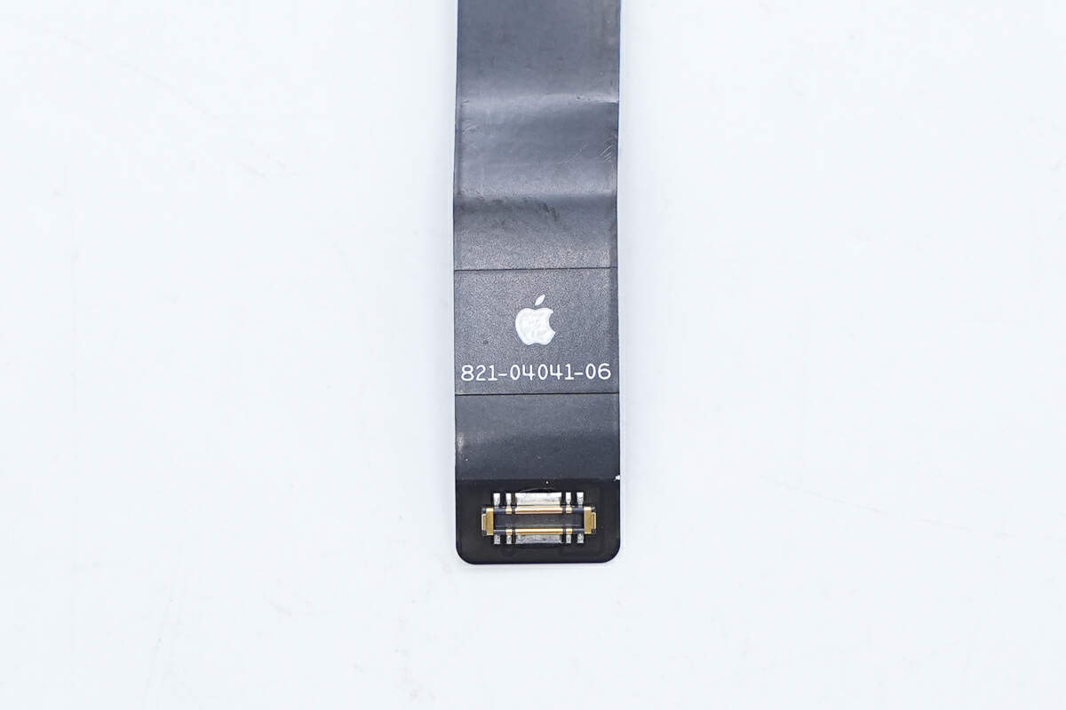
The Apple logo is printed on the cable.
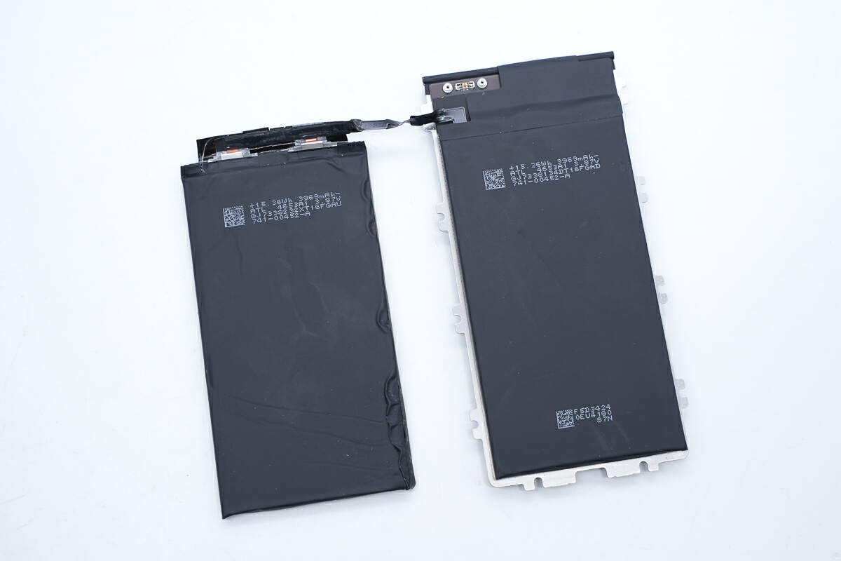
The batteries are connected by the cable.
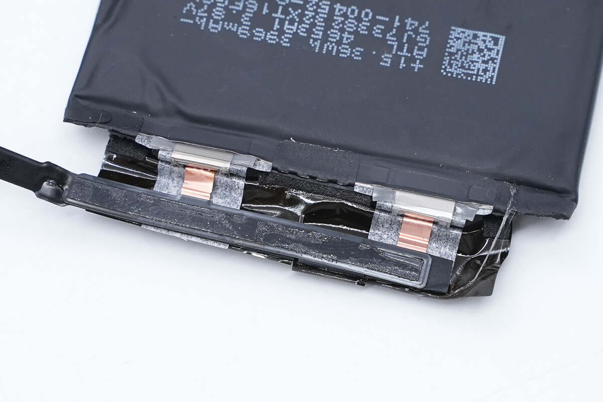
The cable is welded to the battery lugs.
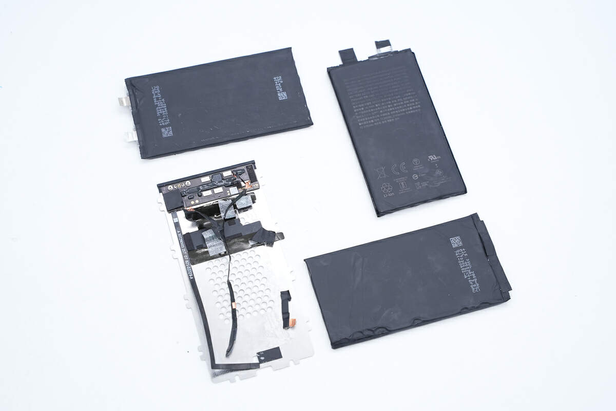
These are the three batteries and the battery protection PCB.
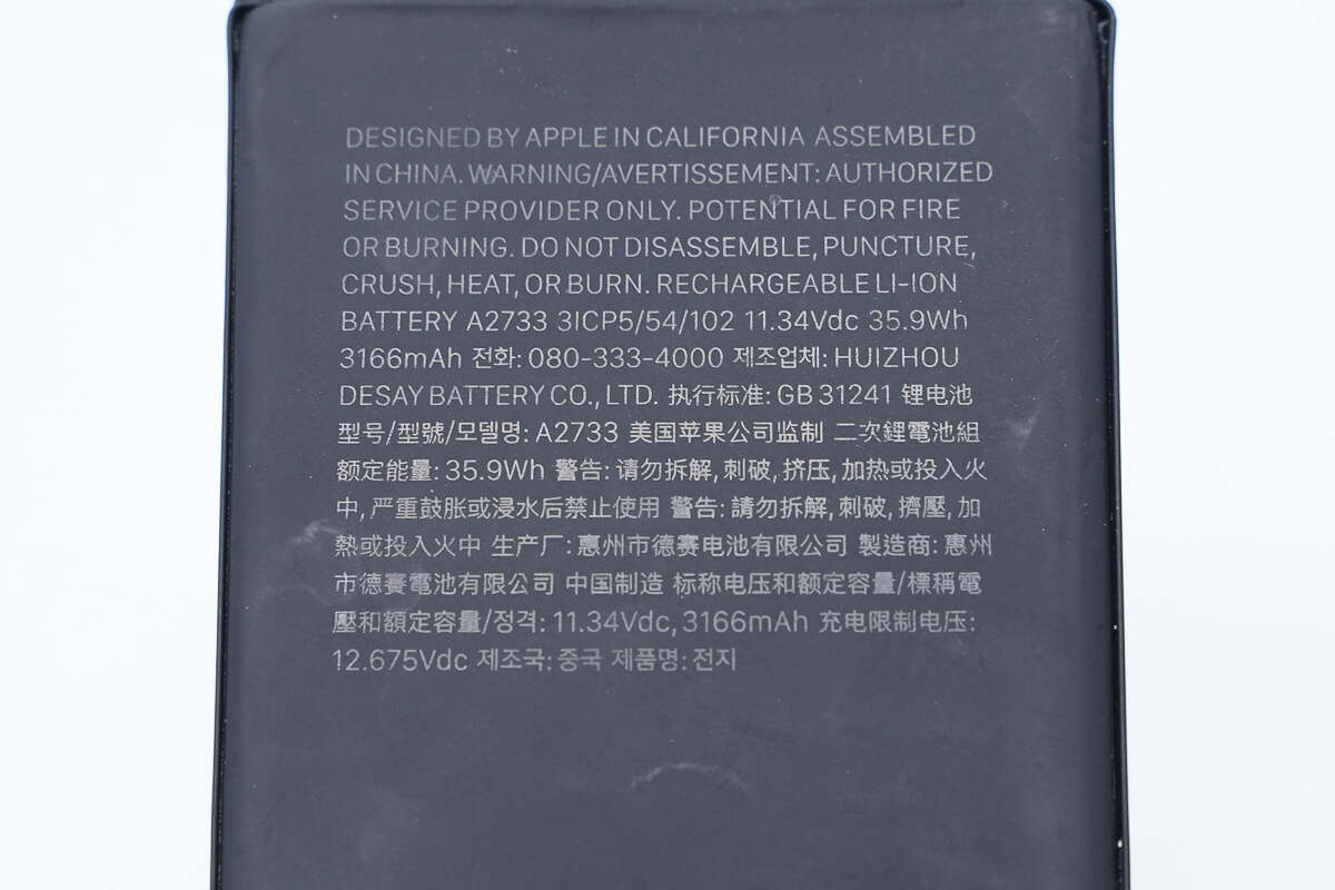
The battery pack is from Desay. The nominal voltage is 11.34V, the charging limit voltage is 12.675V, the rated capacity is 3166mAh, and the rated energy is 35.9Wh.
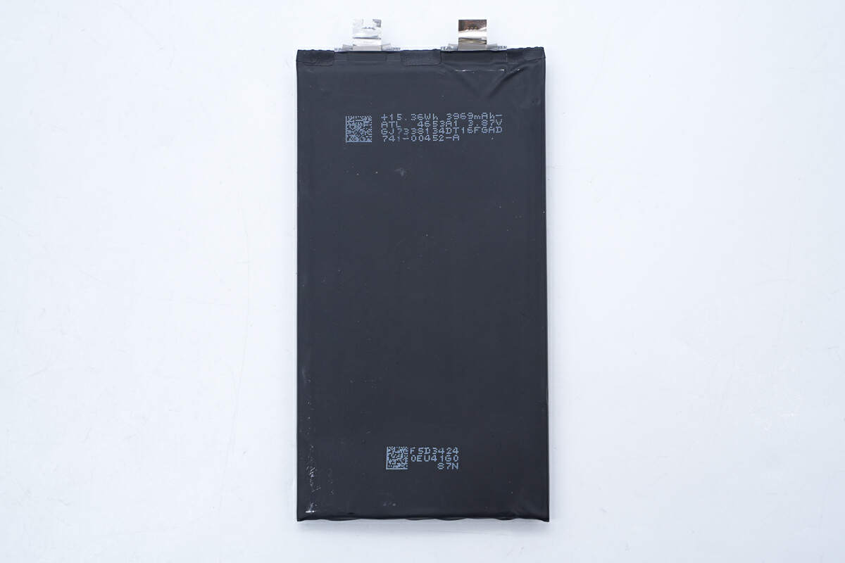
The battery is from ATL.
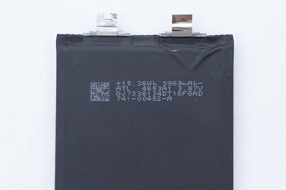
The battery has a rated energy of 15.36Wh, a rated capacity of 3969mAh, and a rated voltage of 3.87V.
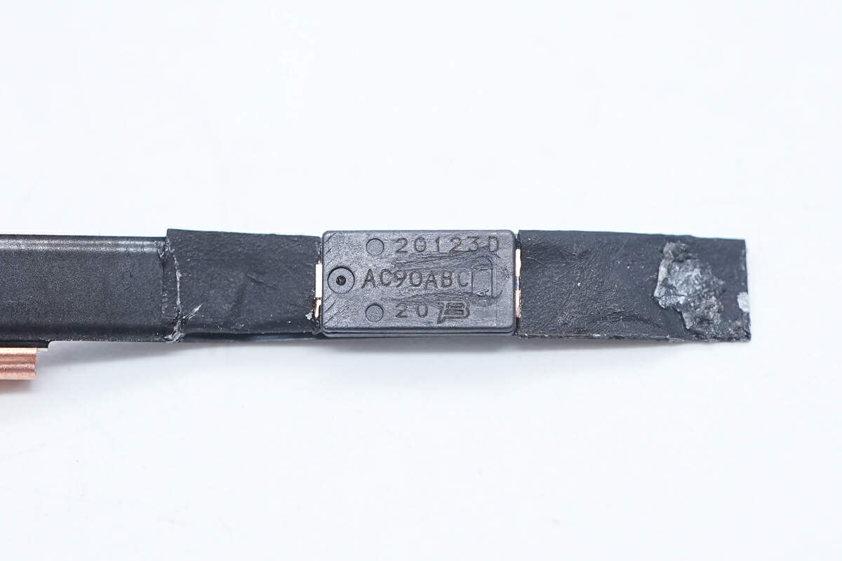
The thermal protector in series with the battery is from the BOURNS AC series for overheating protection. Model is AC90ABD.
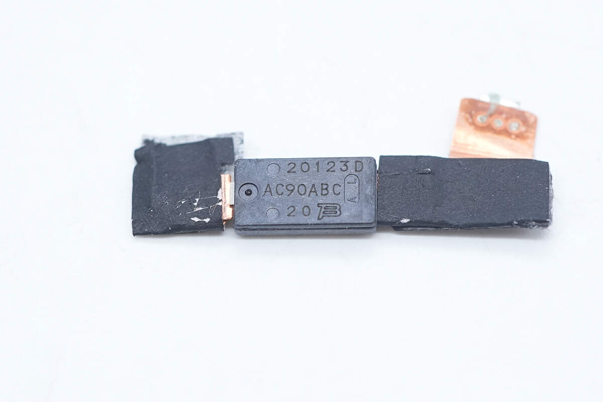
The other thermal protector model is the same.
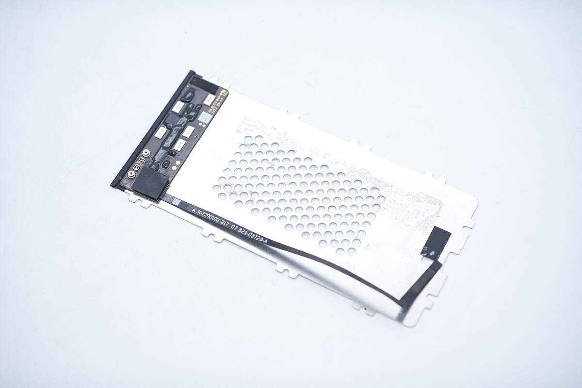
The battery protection PCB is glued to the metal plate.
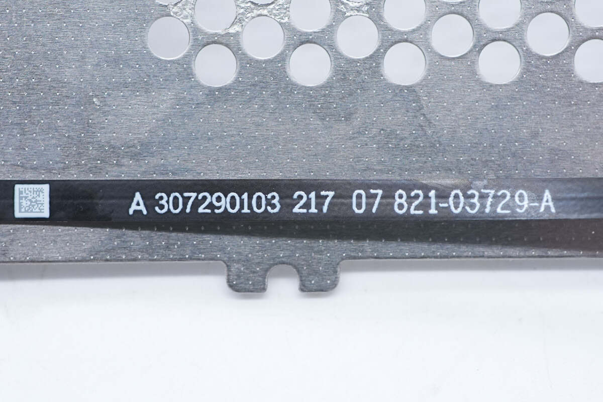
The thermistor is connected to the protection PCB via a cable.
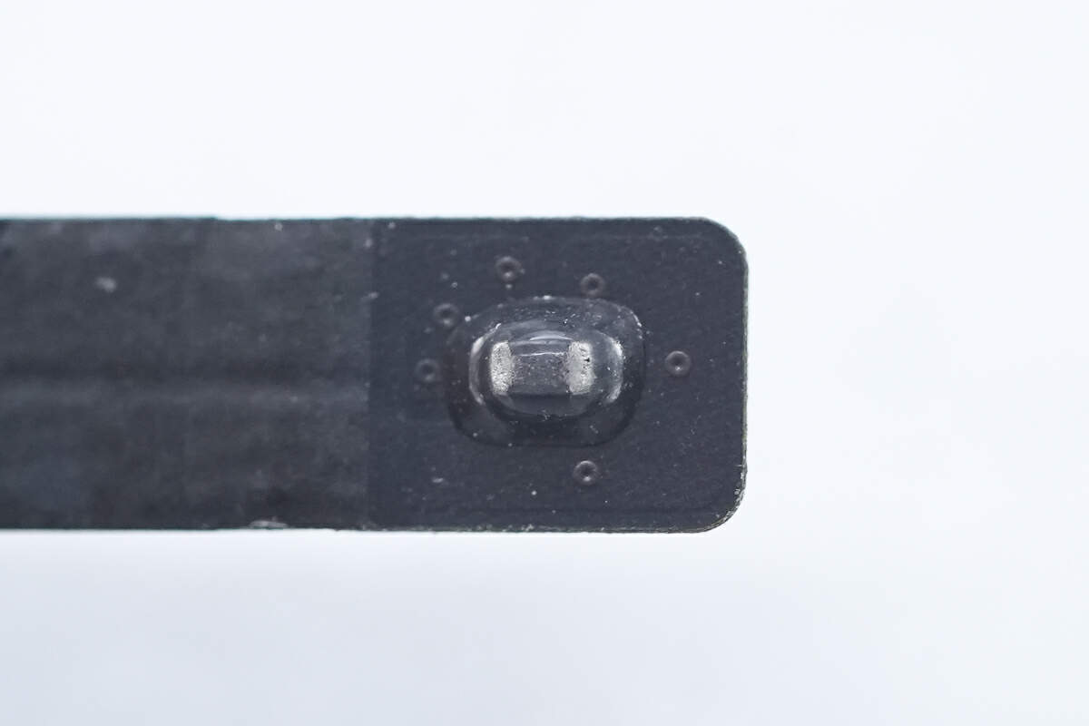
The thermistor used to detect battery temperature is sealed with glue for protection.
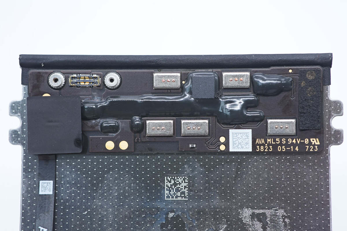
The battery protection PCB is attached to the metal plate with double-sided tape.
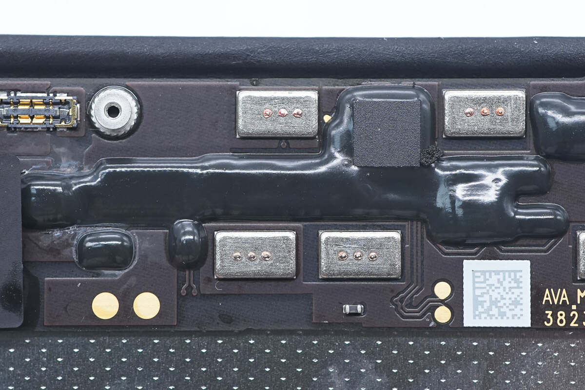
The components on the protection PCB are reinforced with potting compound.
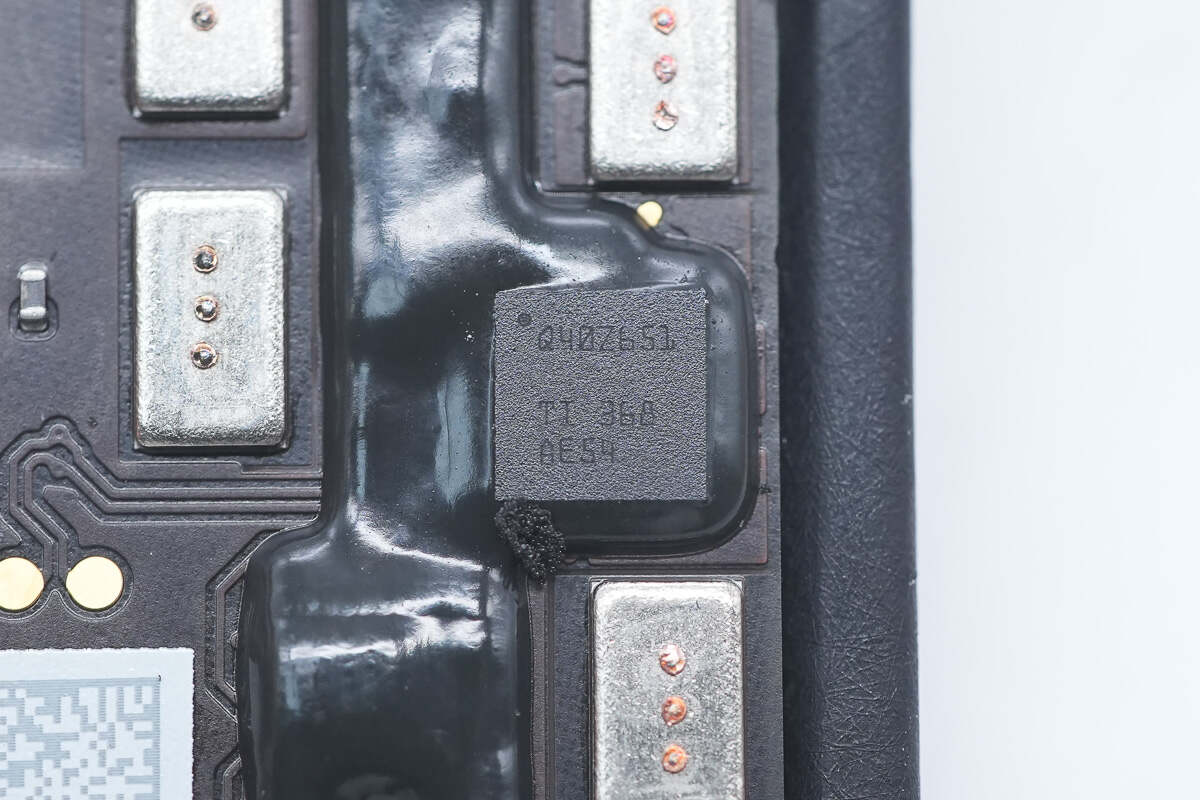
The battery protection chip is from TI. Model is BQ40Z65.
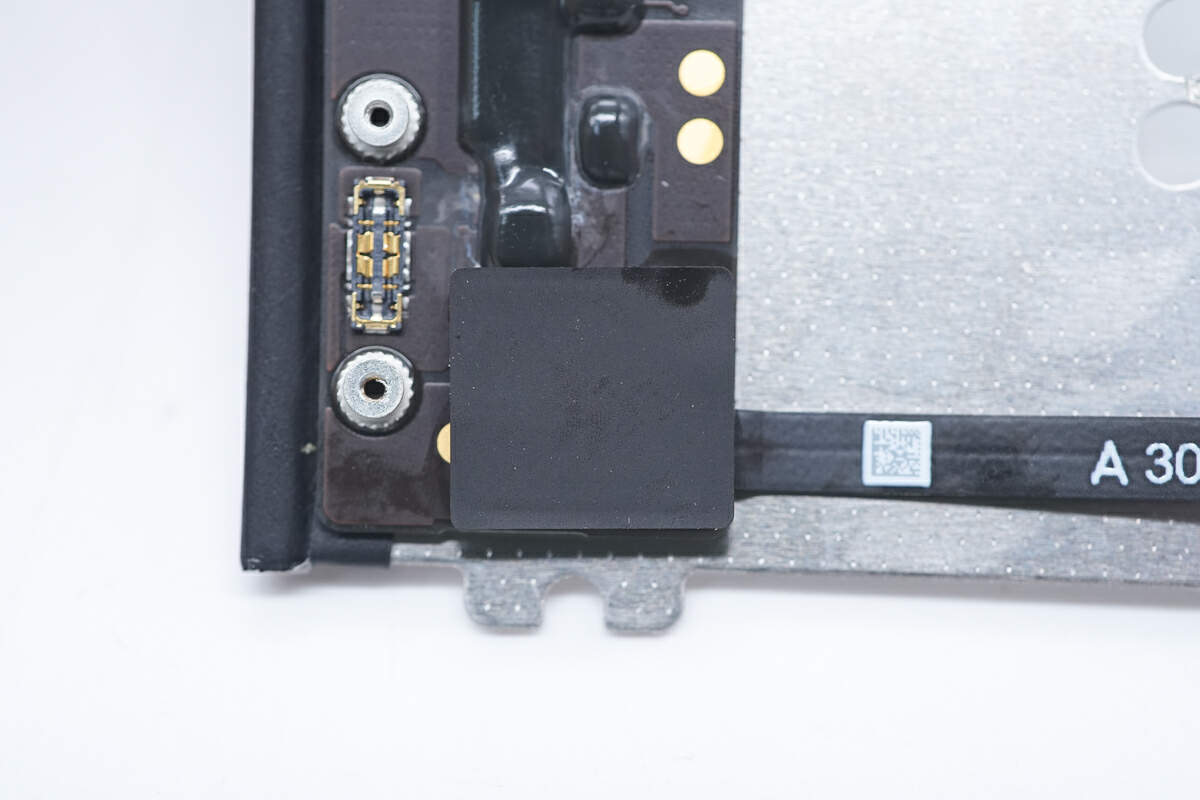
This is a thermistor.
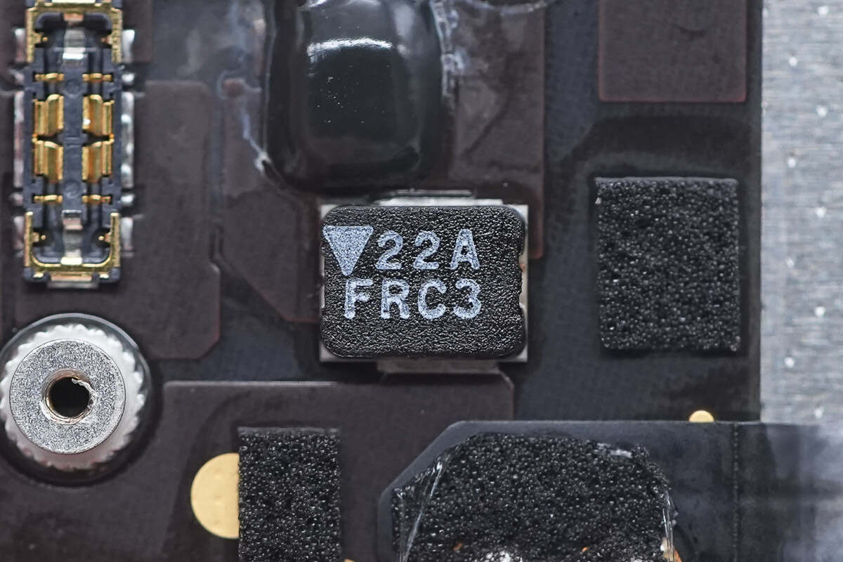
The fuse marked with 22A FRC3 is used for overcurrent protection and battery overcharge protection.
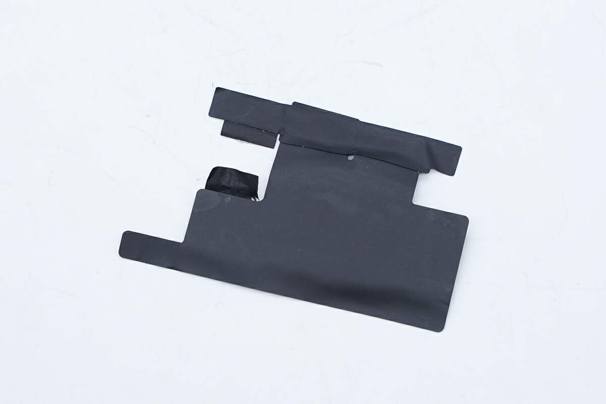
The battery protection board is insulated by a mylar sheet.
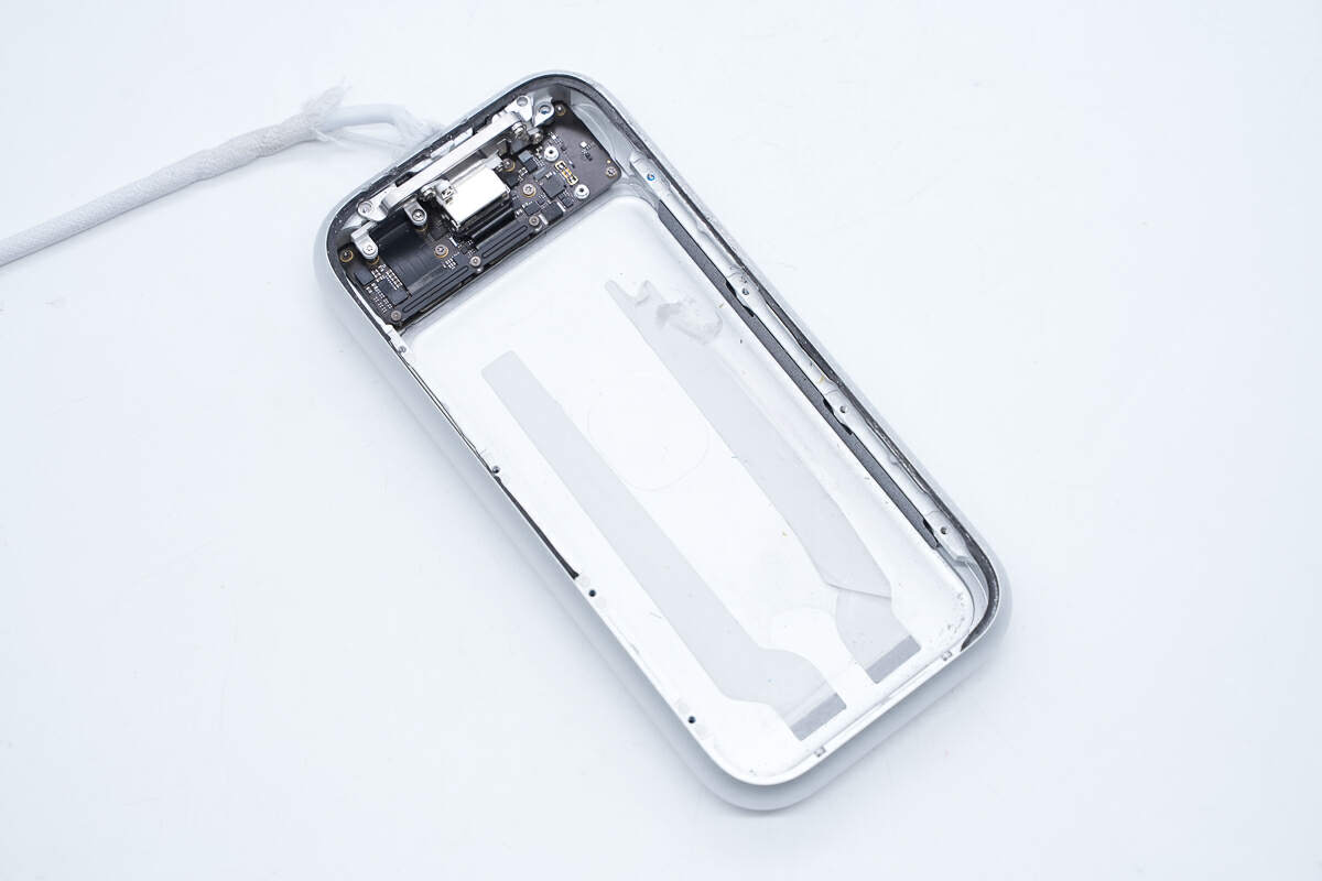
The PCBA module is fixed inside the case.
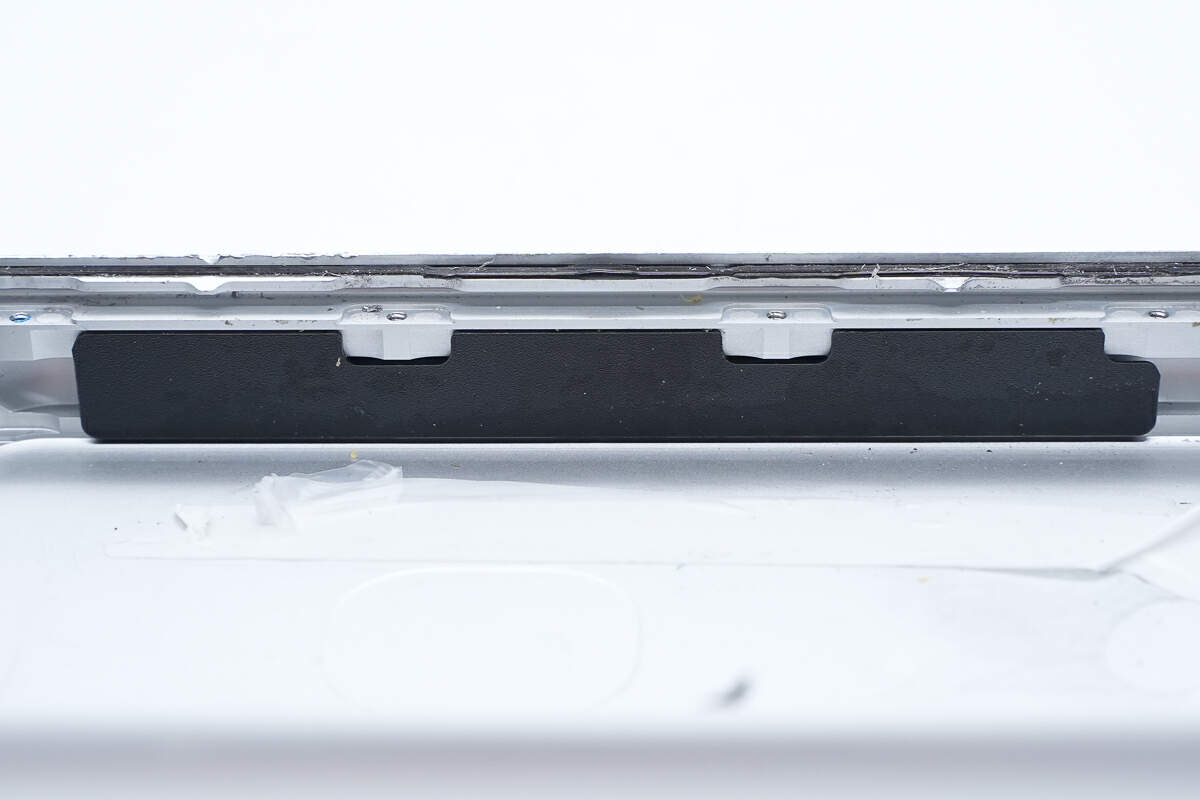
The mylar sheet is pasted inside the case for insulation.
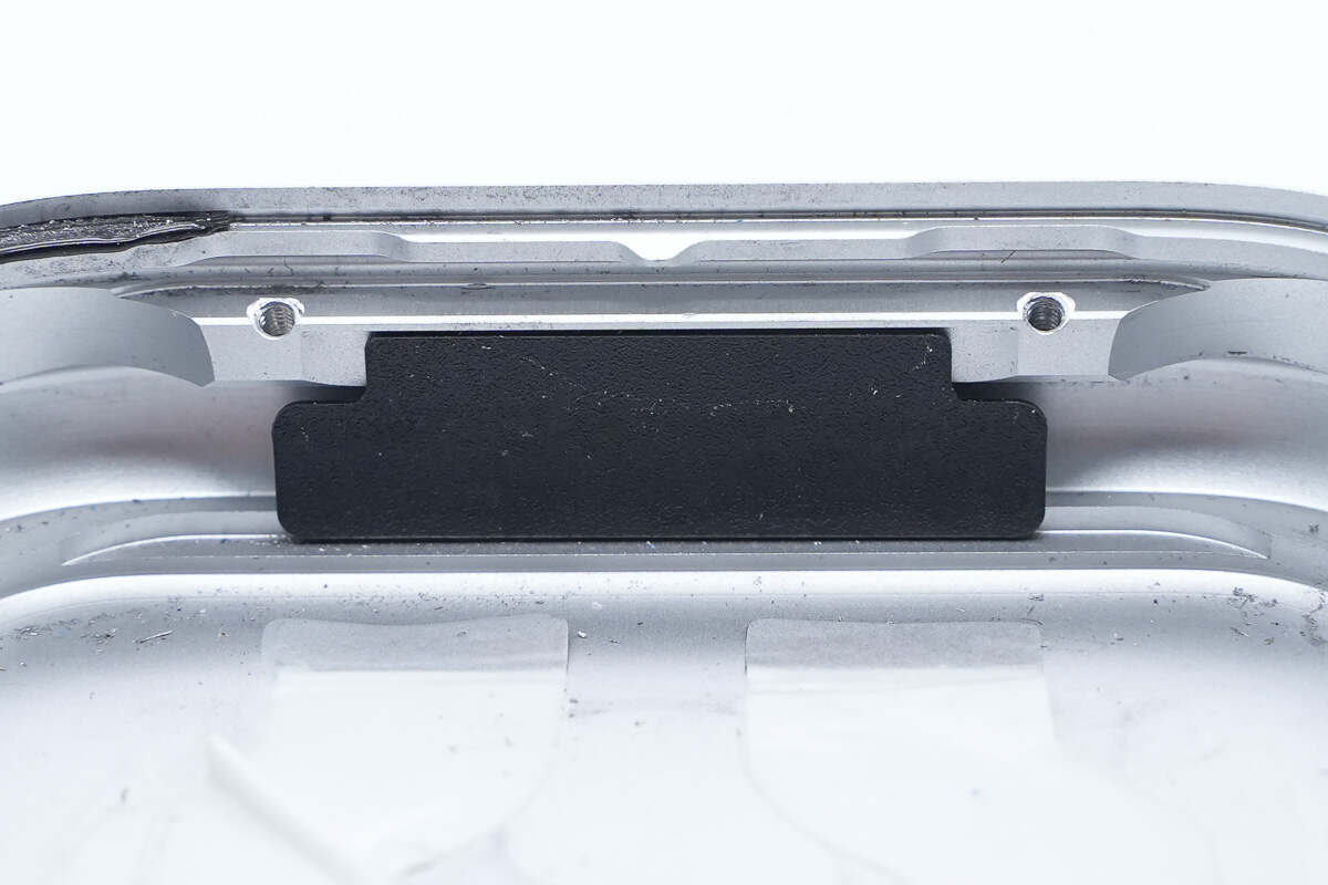
There is a mylar sheet on the bottom of the case for insulation.
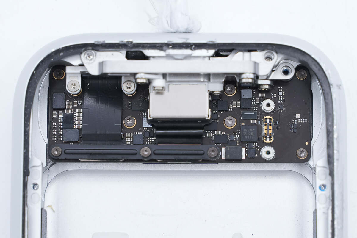
The PCBA module and connector are fixed in the case with screws.
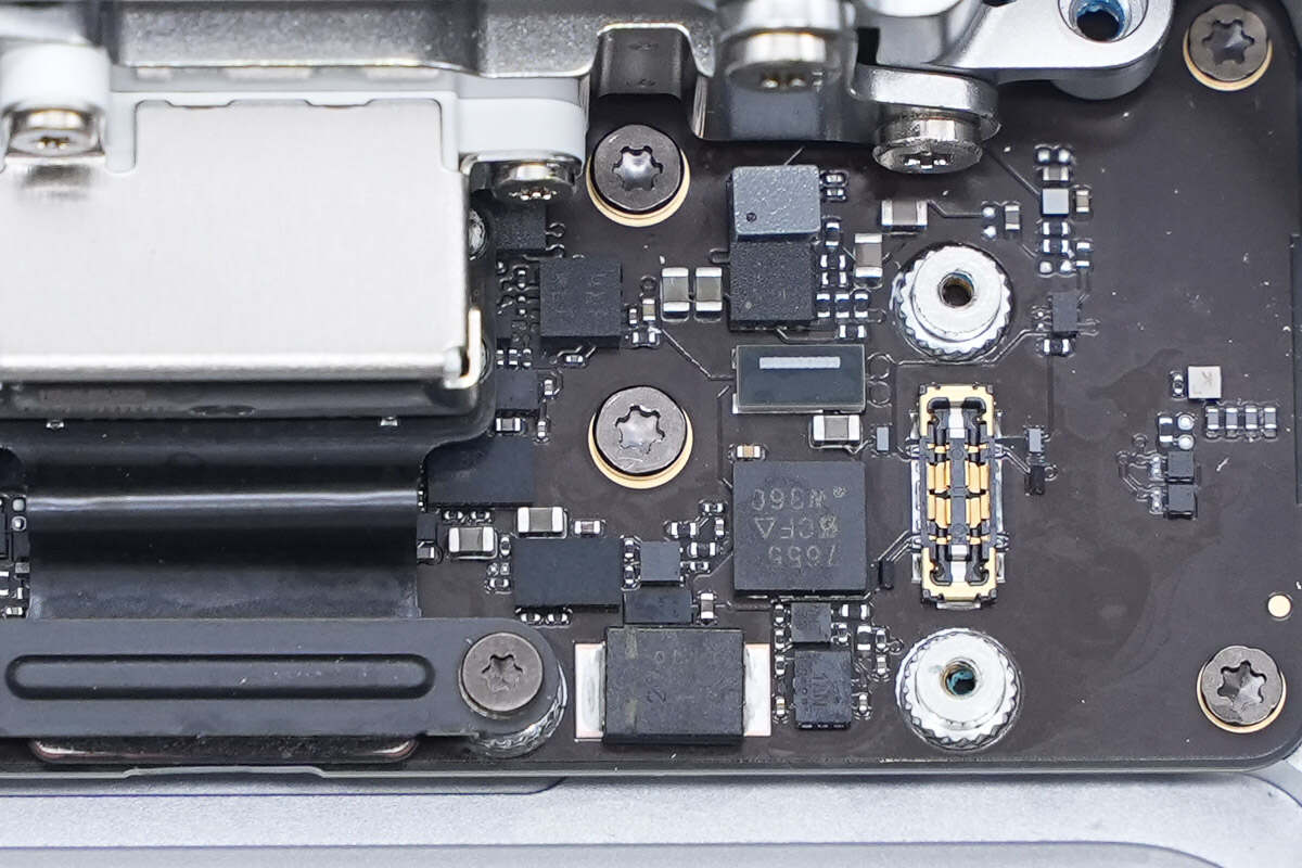
These are the screws used to secure the PCBA module.
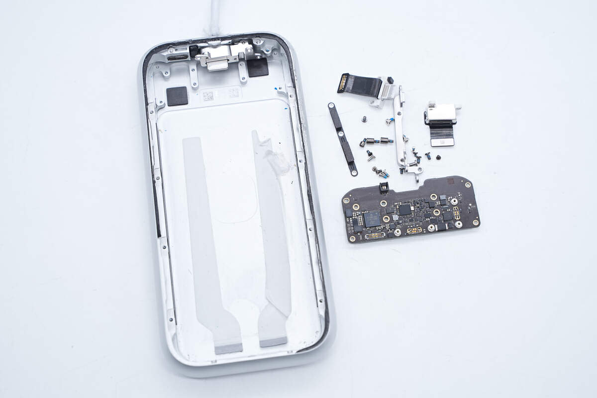
Unscrew the screws and take out the connector and PCBA module.
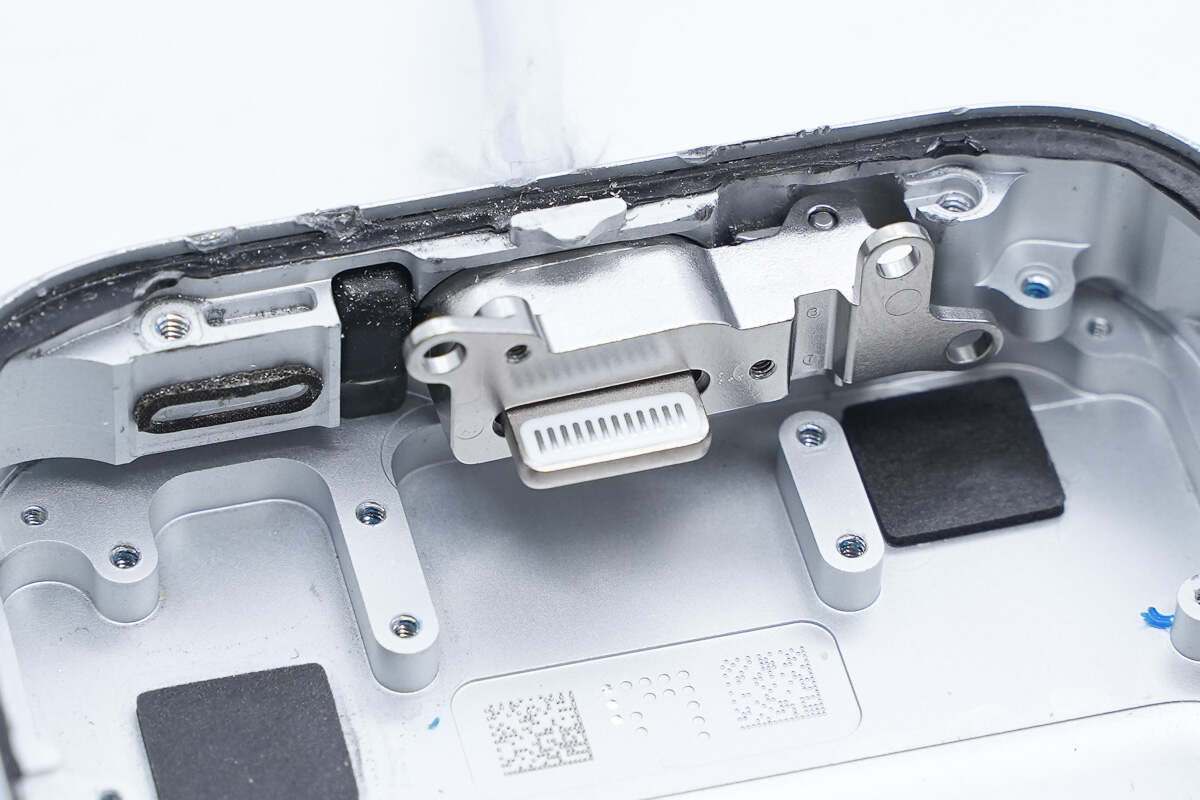
There is a widened Lightning plug which has 12 pins.
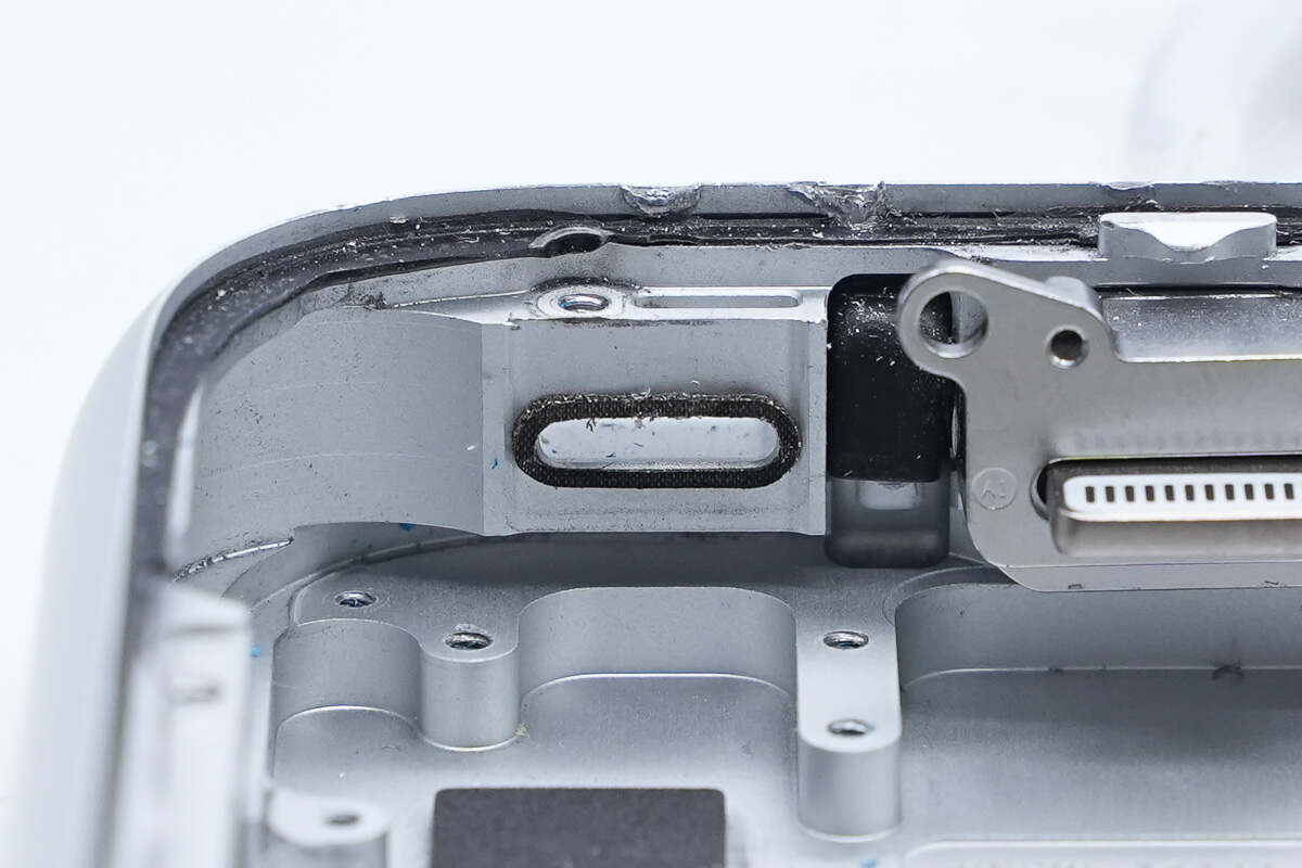
The USB-C socket is sealed with a rubber ring.
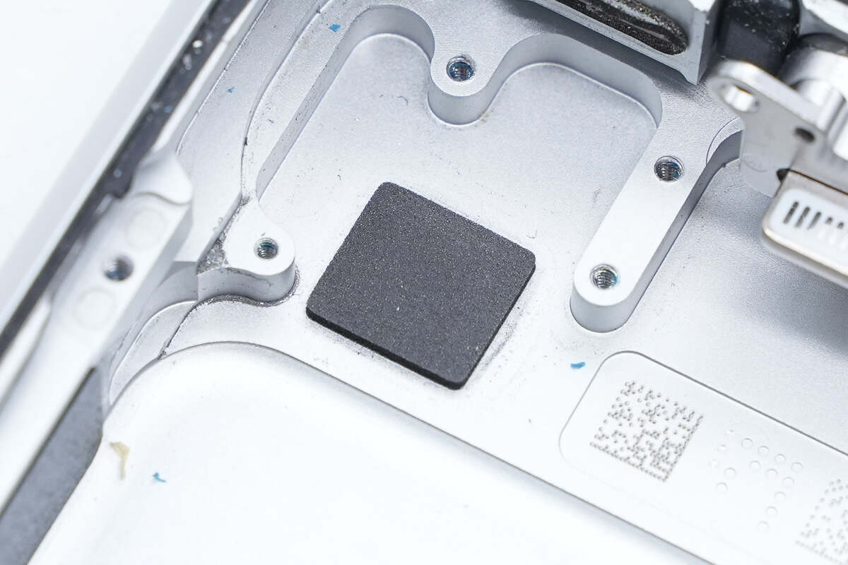
There is a buffer pad at the position corresponding to the inductor.
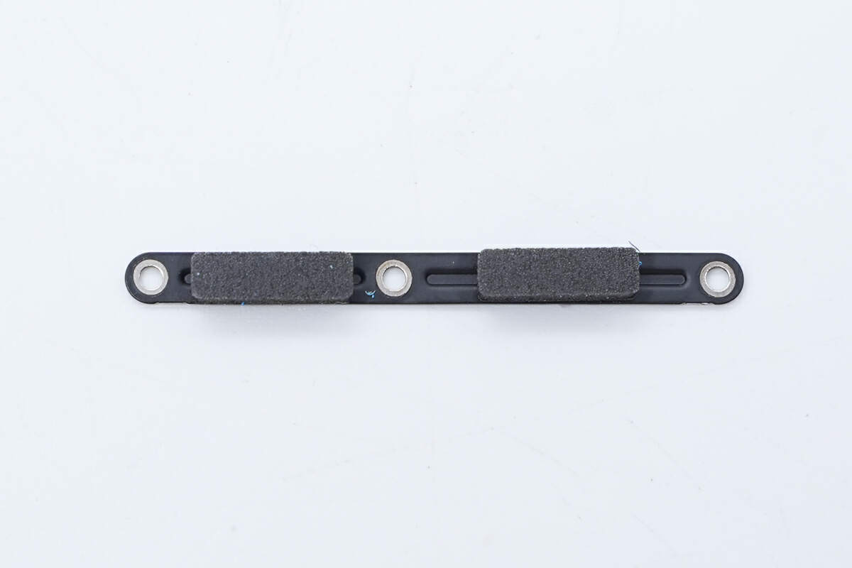
This is the pressure plate that secures the USB-C socket and the output cable socket.
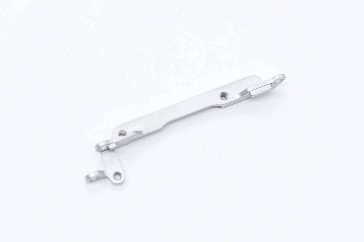
This is the bracket that holds the connector in place.
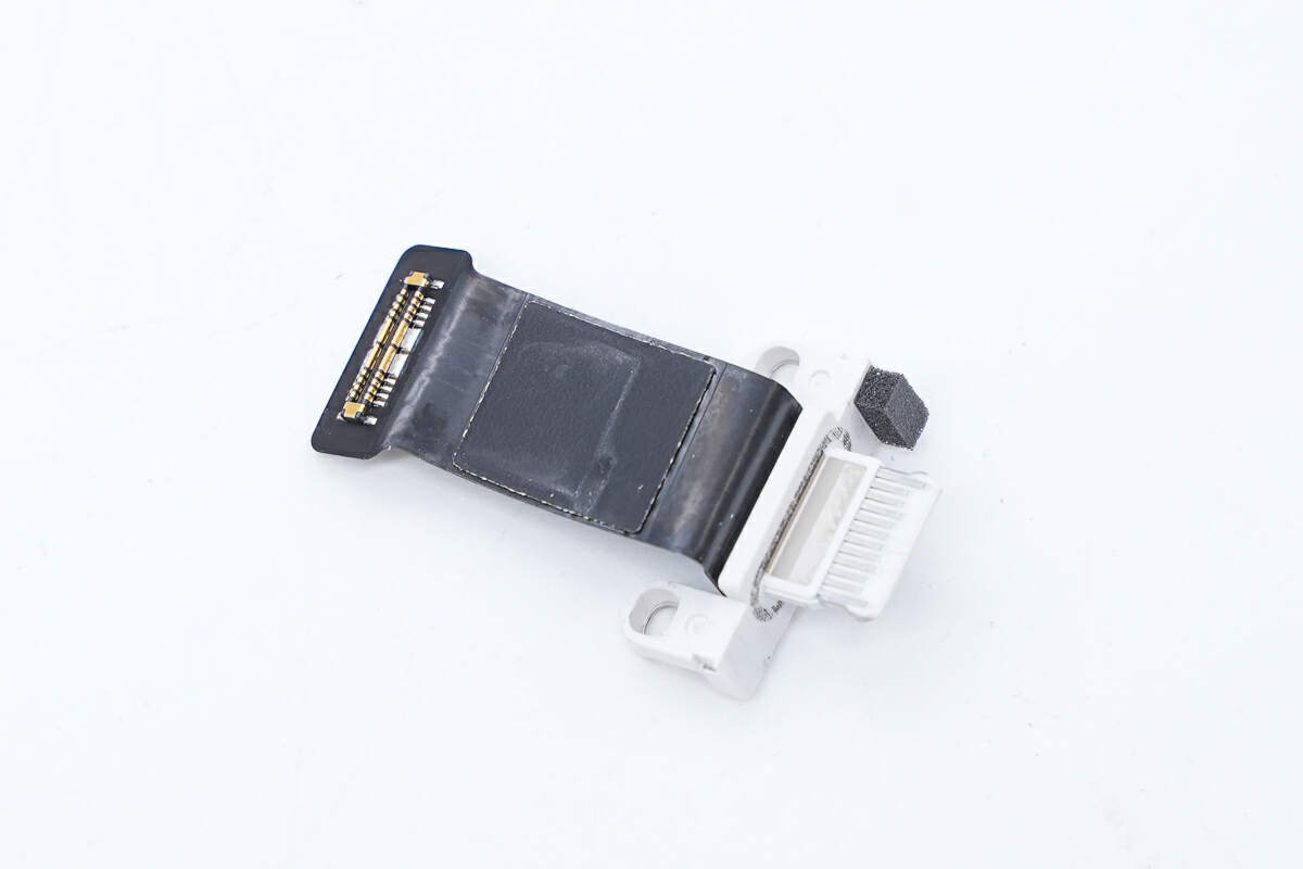
The USB-C socket is connected via a cable, and the socket has silver contacts.
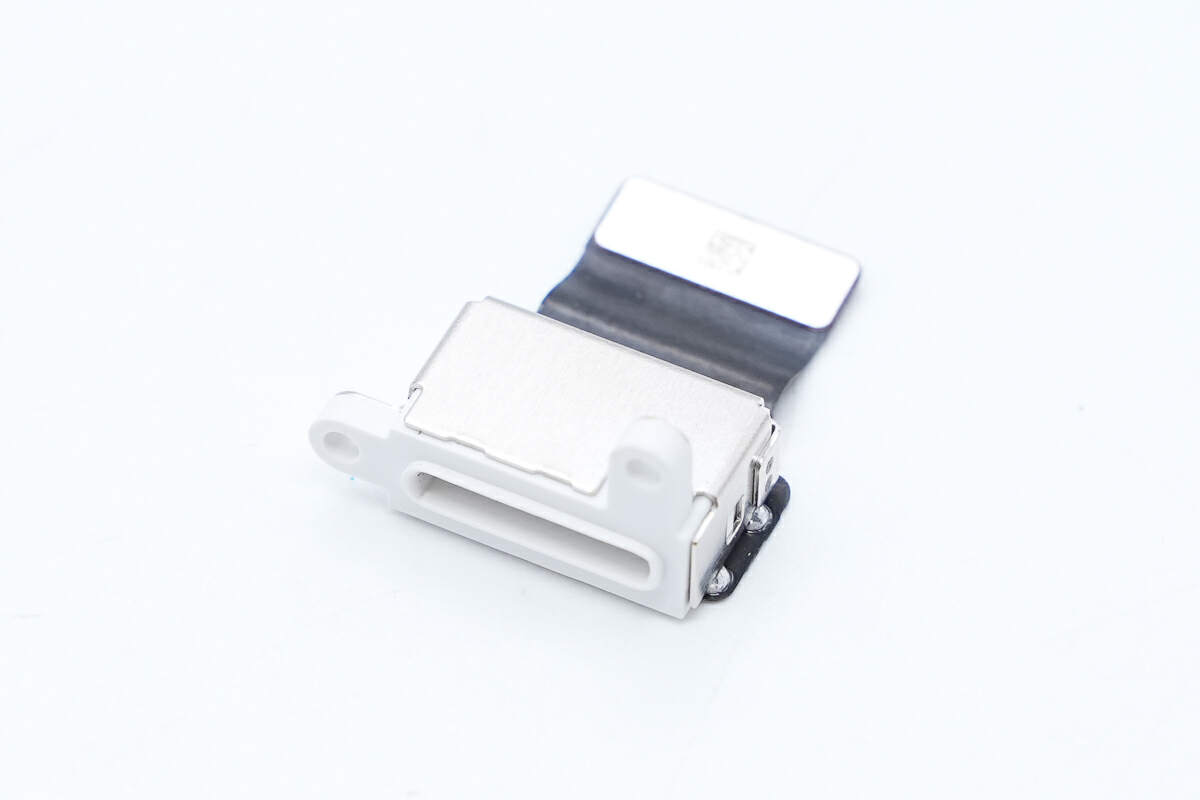
The widened Lightning socket is reinforced with a metal case.
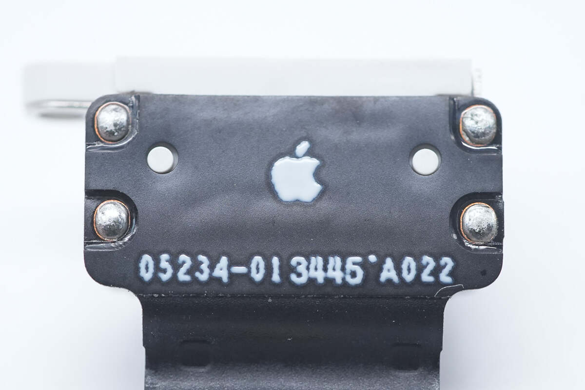
There is an Apple logo on the cable.
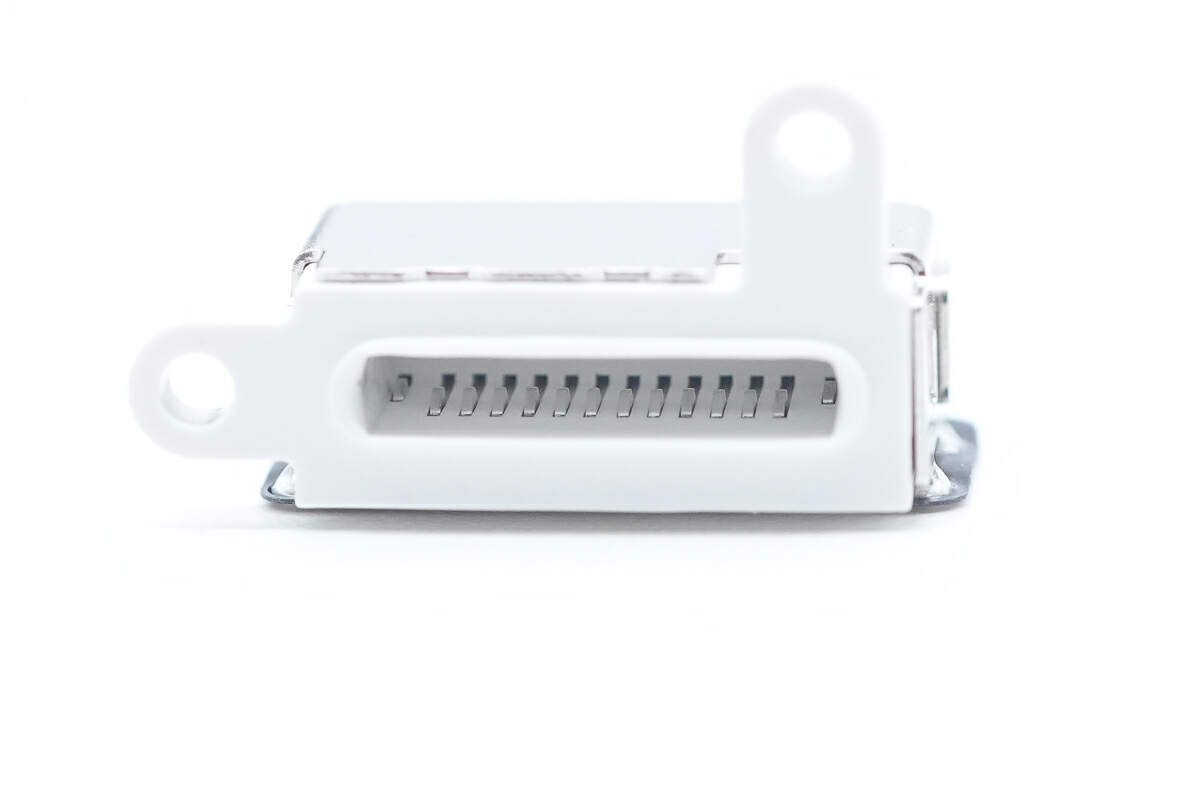
The widened Lightning socket has contacts inside.
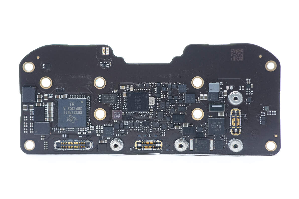
The front of the PCBA module has two synchronous buck converters, a protocol chip, memory, and an MCU.
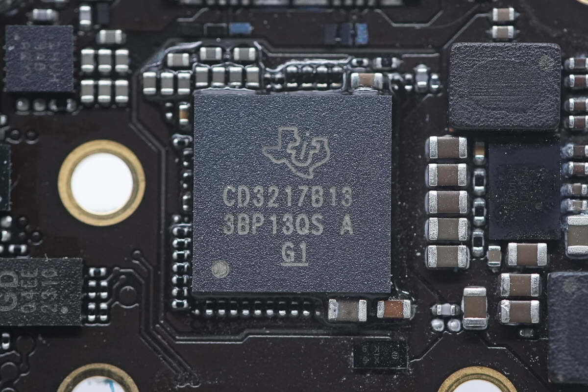
The USB PD controller is from TI. Model is CD3217B13.
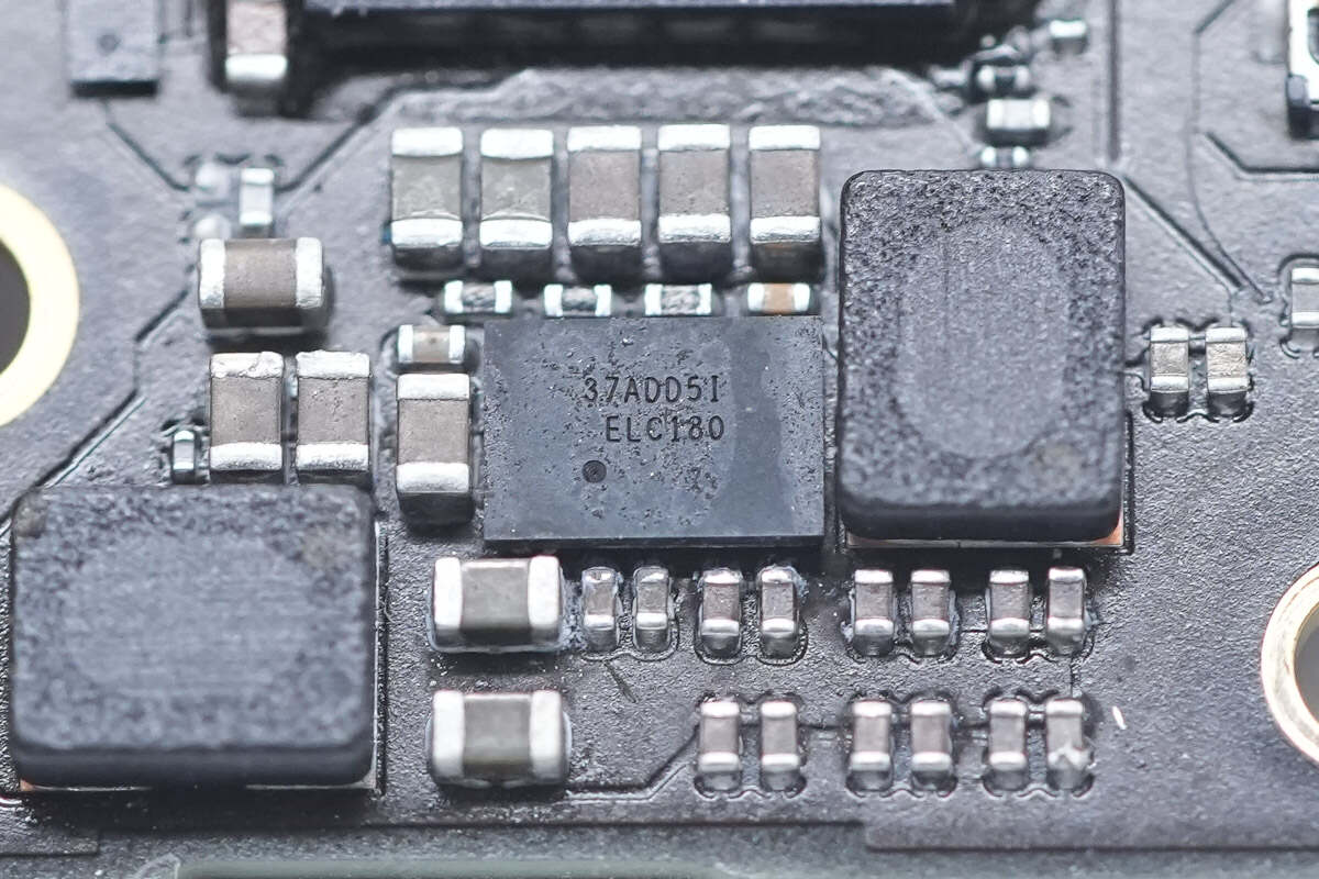
The synchronous buck converter on the left is from TI and adopts DSBGA24 package. It supports an operating voltage range of 4-15V and a continuous output current of 6A. Model is TPS62180.
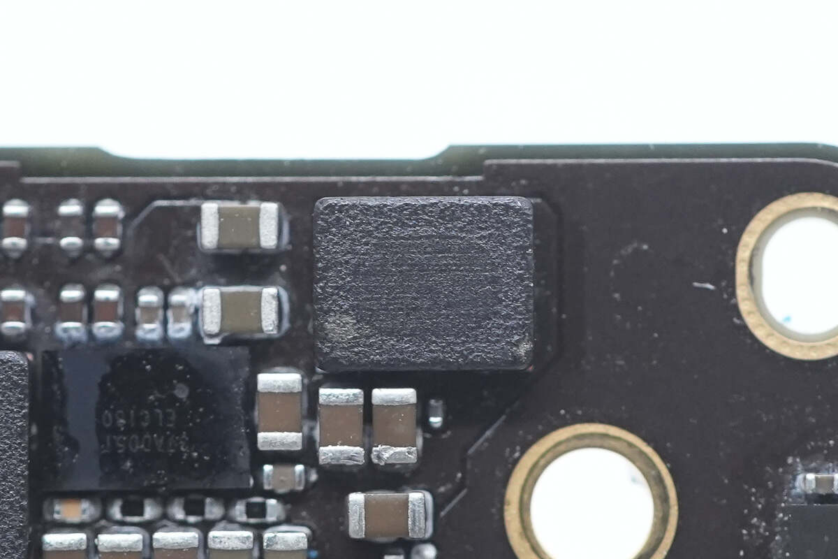
This is the buck inductor used with it.
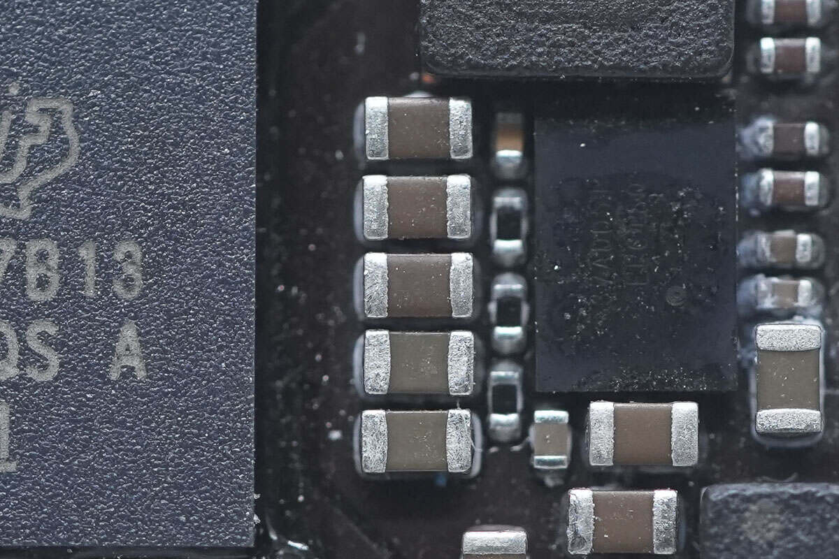
These are five MLCC capacitors connected in parallel.
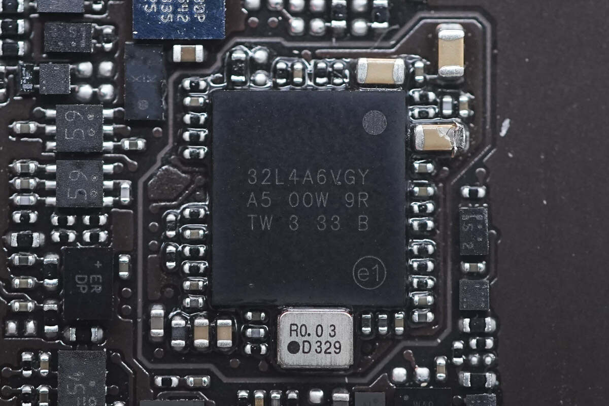
The MCU is from ST and adopts WLCSP100L package. It integrates 1MB FLASH and 320KB SRAM and has multiple protection functions. It has an internal integrated ARM Cortex-M4 CPU. Model is STM32L4A6VG.
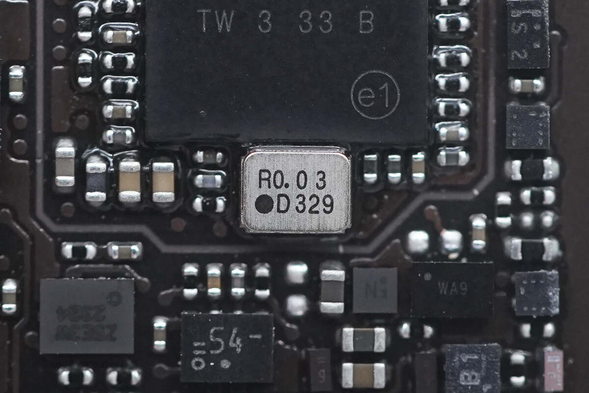
This is an external clock crystal.
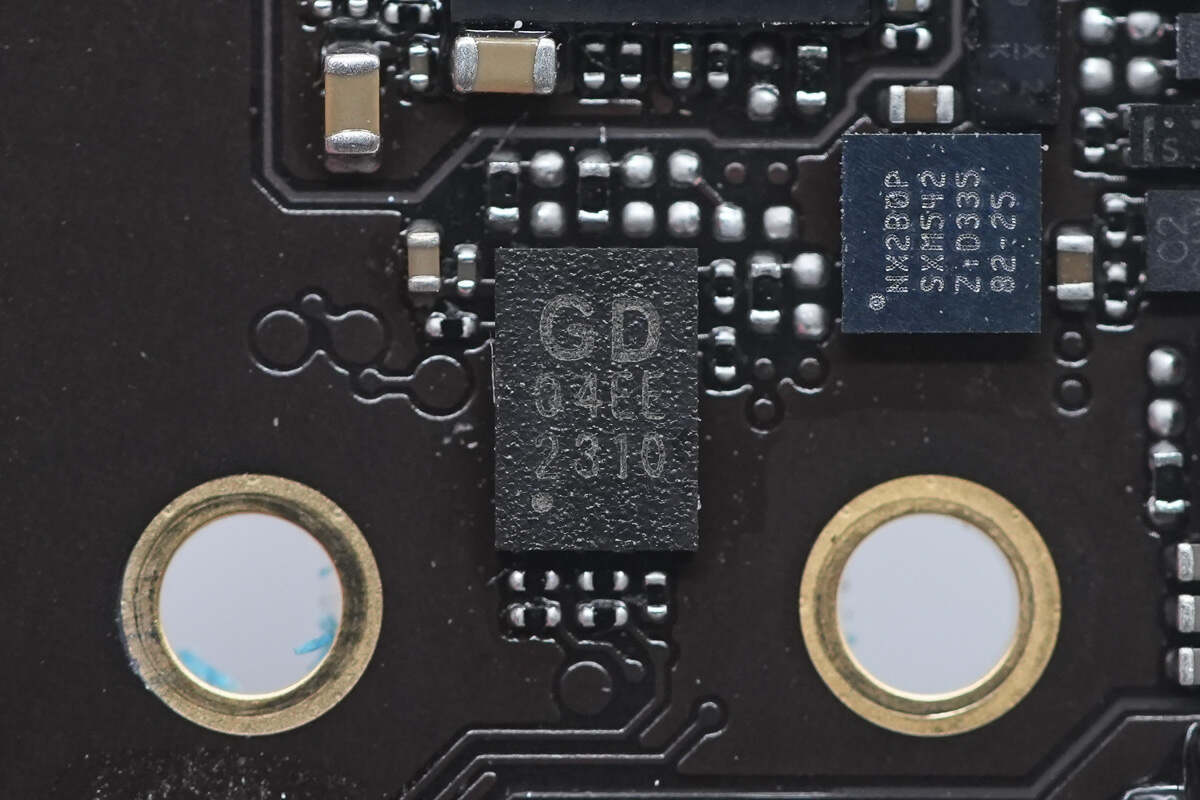
The external memory is from GigaDevice and adopts USON-8 package. Model is GD25Q80EEIG. 1MB.
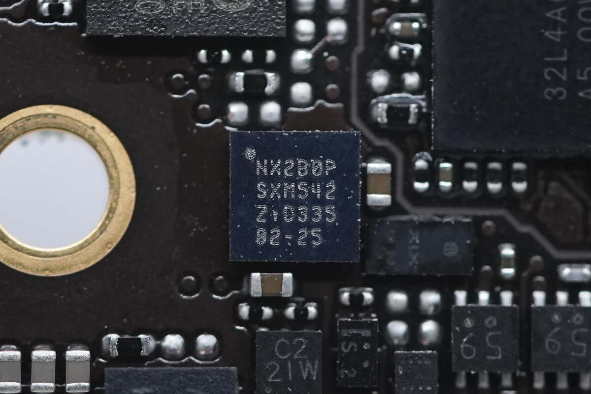
This chip is marked with NX2B0P.
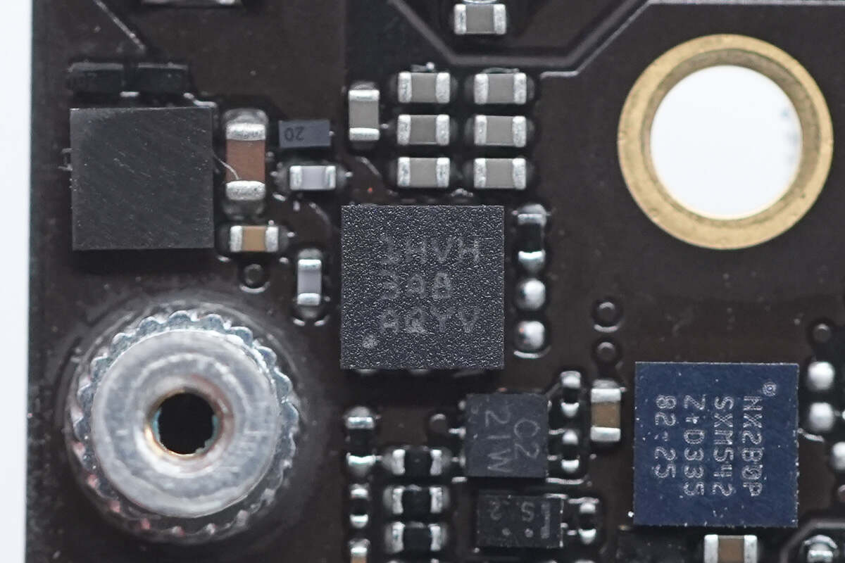
The TVS marked with 1HVH is from TI and adopts 2*2 SON package. Its shutdown voltage is 22V and is used for transient overvoltage absorption. Model is TVS2200.
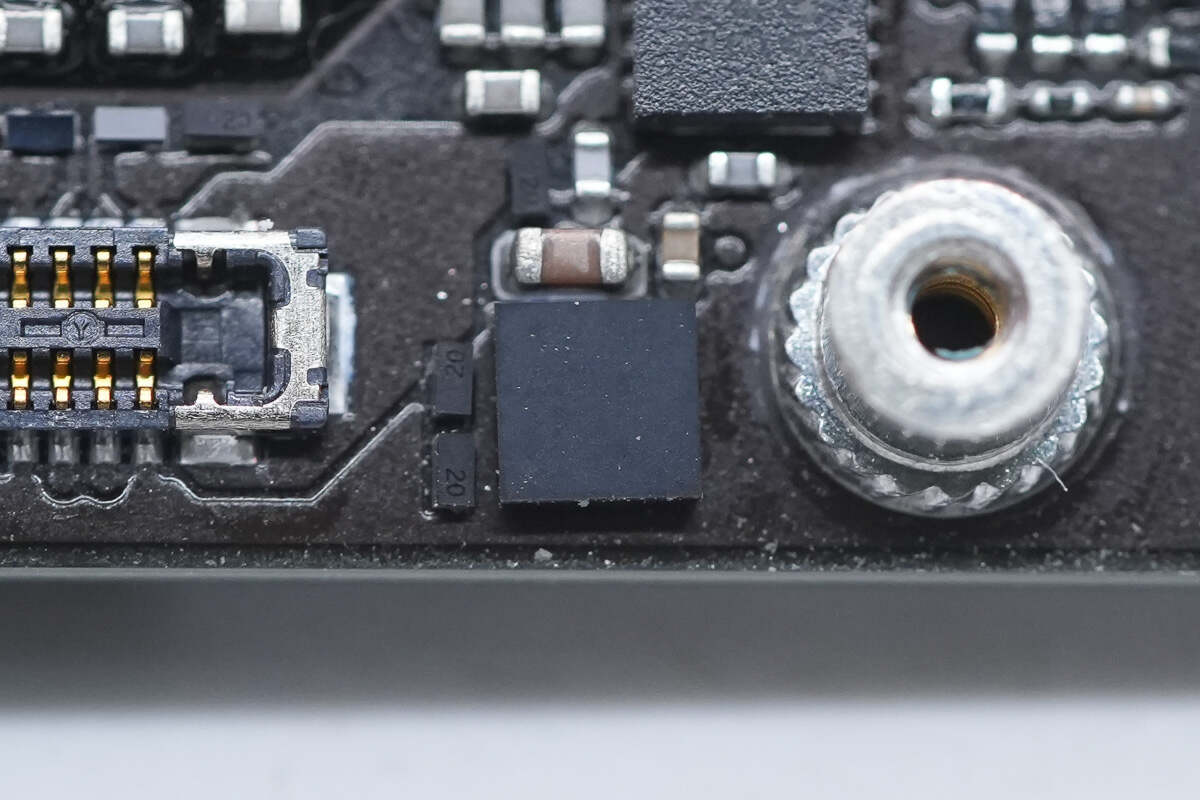
The ESD overvoltage protection chip is from TI and adopts DSBGA16 package. It is used for short circuit protection of CC1, CC2, SBU1 and SBU2 to VBUS and for ESD protection. Model is TPD4S311A.
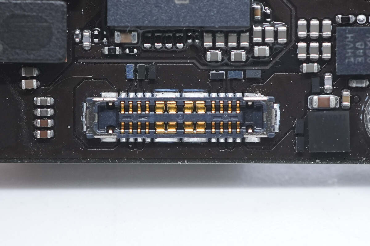
This is the connector for the USB-C socket.
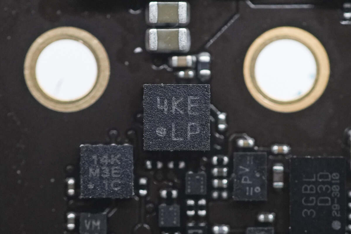
The gyroscope chip marked with 4KE LP that detects direction is from BOSCH.
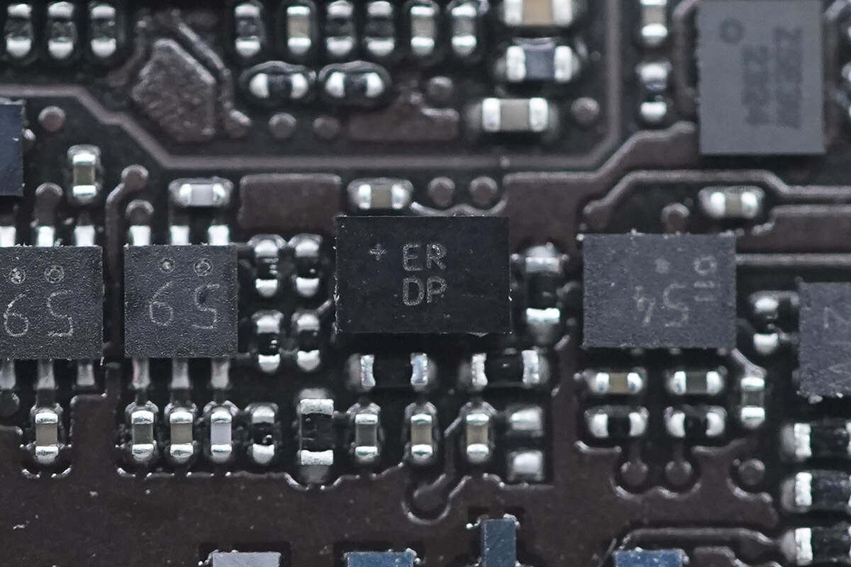
This chip marked with ER DP is from ADI.
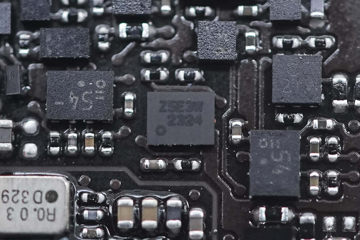
This chip is marked with Z5E3W.
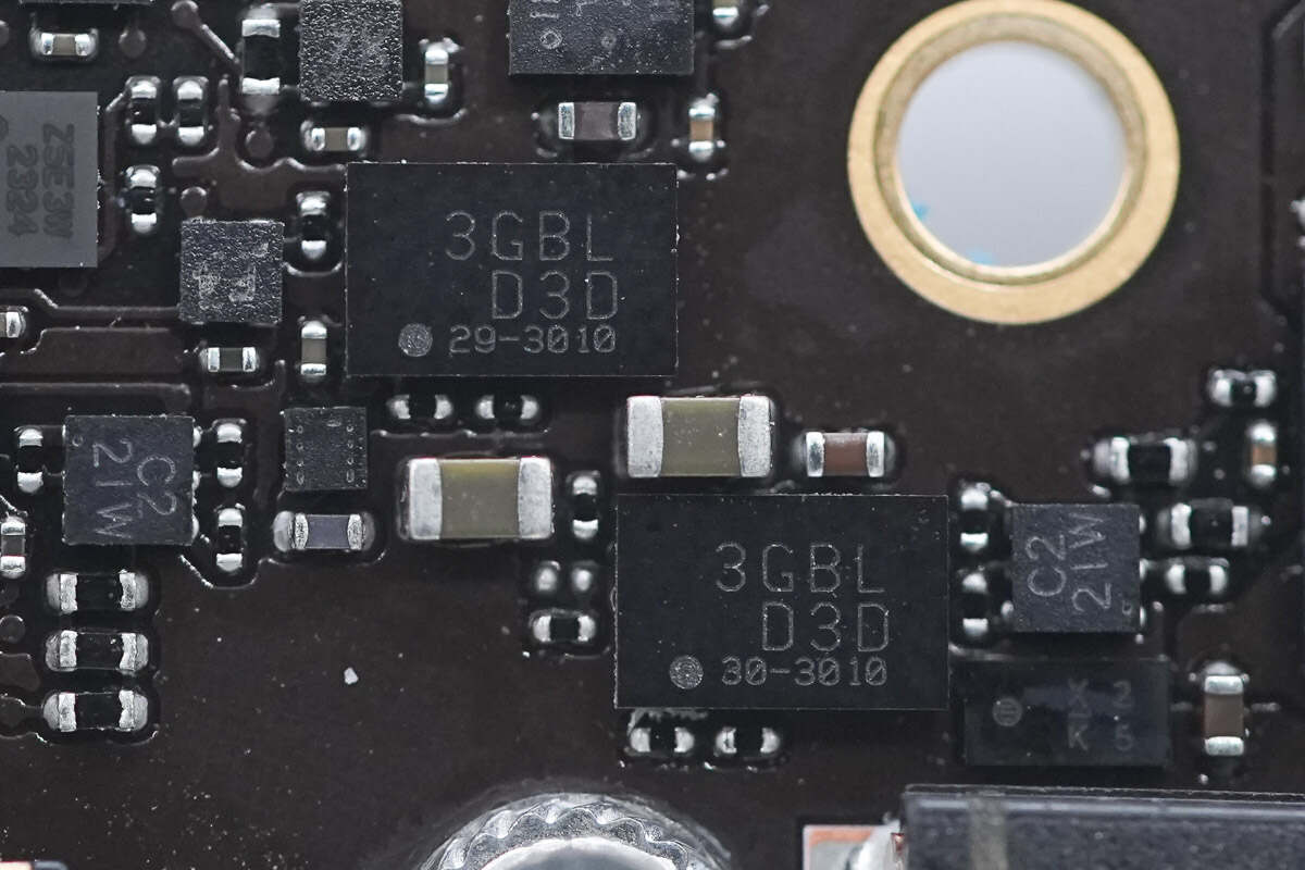
The power switch IC is from onsemi and adopts WLCSP24 package. It has overvoltage protection and overcurrent protection functions. It is suitable for a voltage range of 4-22V and supports a 2-5A over-current limit. Model is FPF2895C.
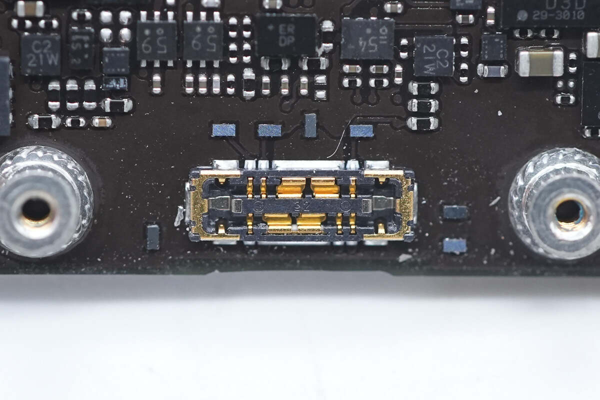
This is the connector of the widened Lightning socket.
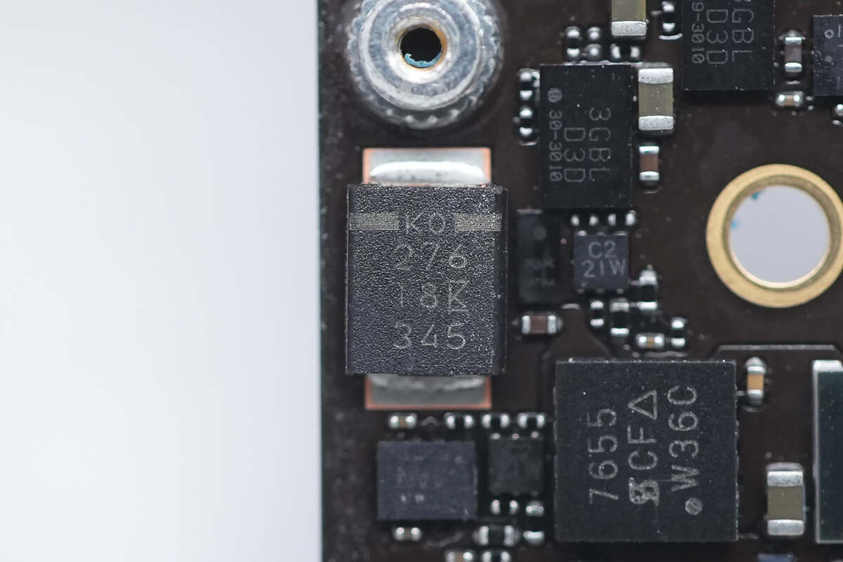
The filter capacitor is from KEMET. 27μF 18V.
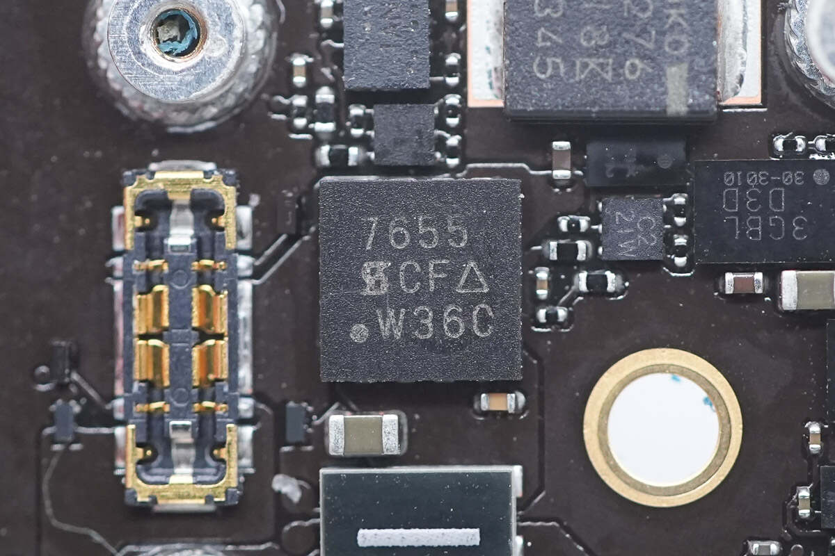
The MOSFET used for output control is from VISHAY and adopts PowerPAK 1212-8 Single package. Model is Si7655DN. -20V 3mΩ.
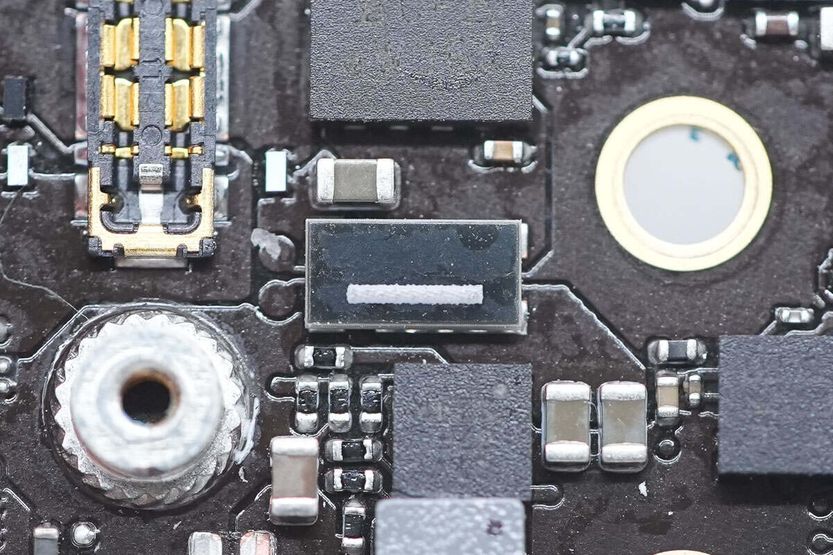
This is the sampling resistor used to sense the current.
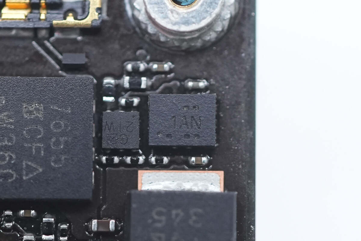
The current detection chip marked with 1AN is from TI and adopts UQFN10 package. It supports a working voltage of 40V and a temperature range of -40~125℃. Model is INA190A1.
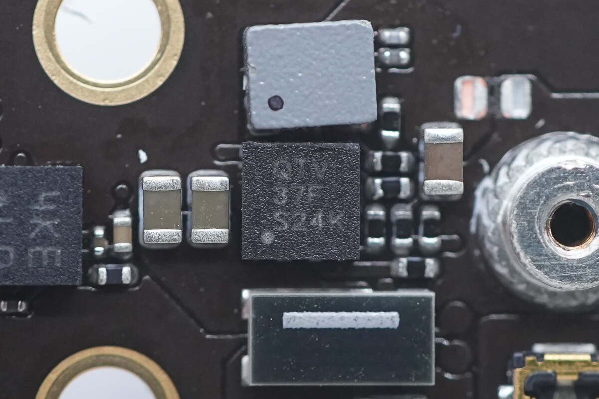
The synchronous buck converter marked with QTV is from TI and adopts 2*2WSON package. It has an input voltage range of 3-17V and an output current of 1A. It has short circuit protection and overheat protection functions. Model is TPS62160.
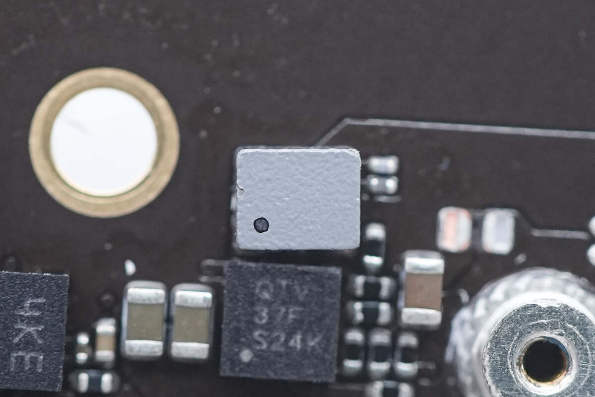
This is the SMD power inductor.
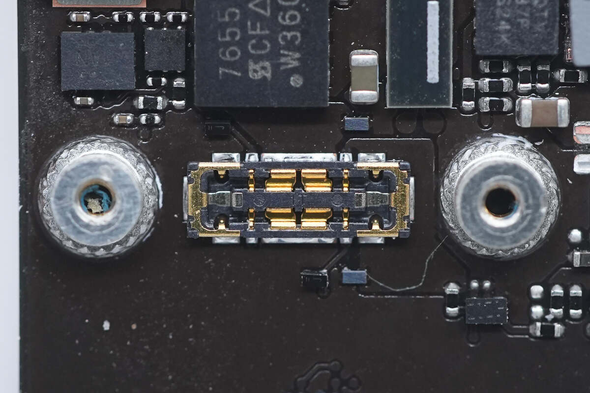
This is the connector for the battery.
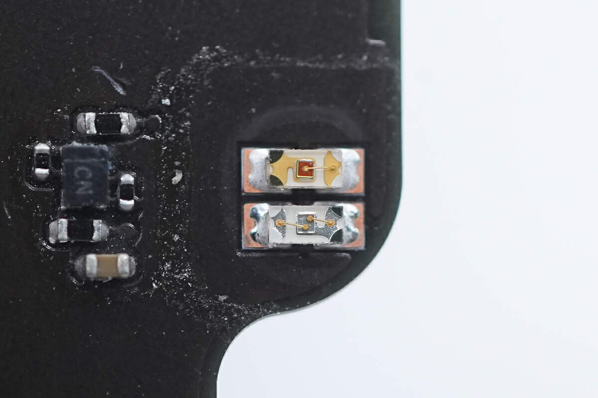
These are two LED indicator lights.
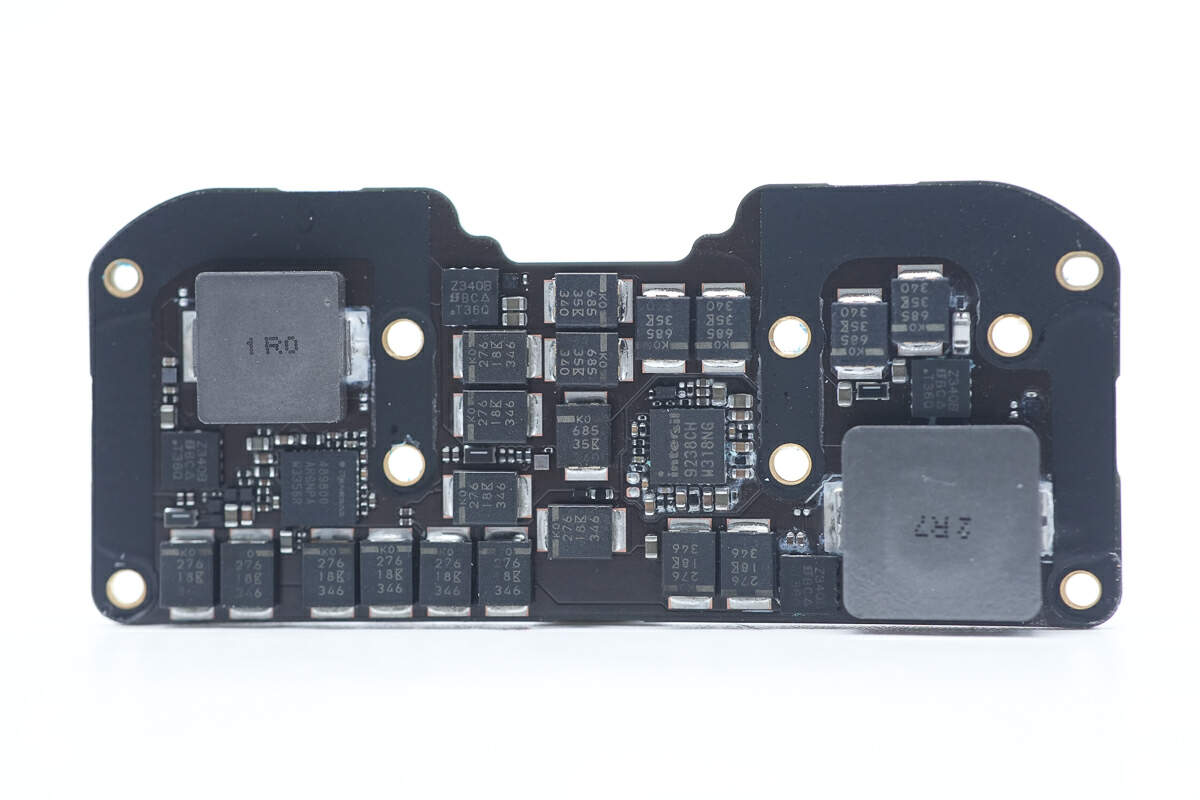
There are two synchronous buck-boost controllers, MOSFETs, inductors, and filter capacitors on the back of the PCBA module.
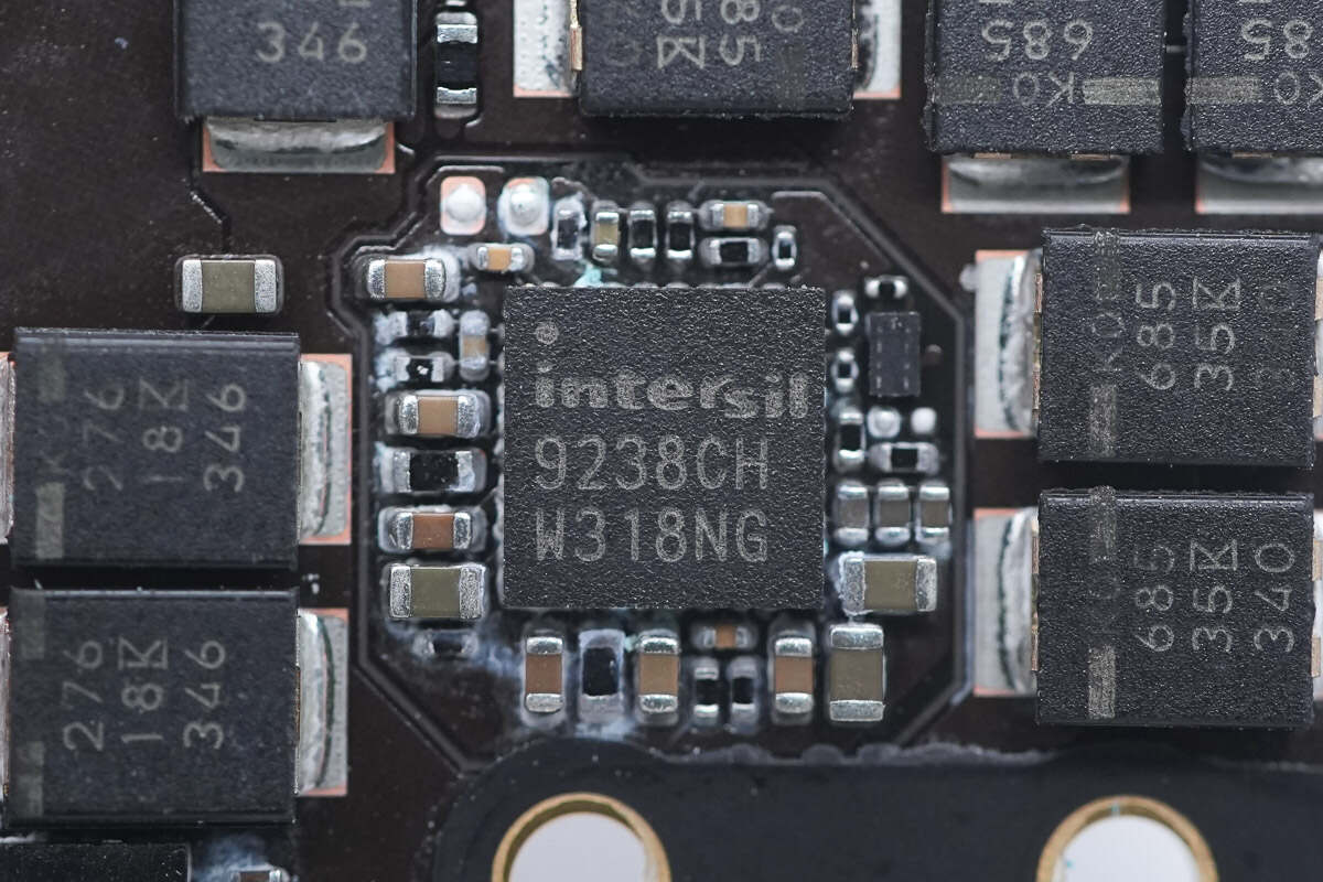
The synchronous buck-boost controller for battery charge and discharge management is from RENESAS and adopts 4*4TQFN package. It supports 1 to 4 lithium battery applications, supports 3.2-23.4V input voltage, and supports 2.4-18.304V output voltage. Model is ISL9238C.
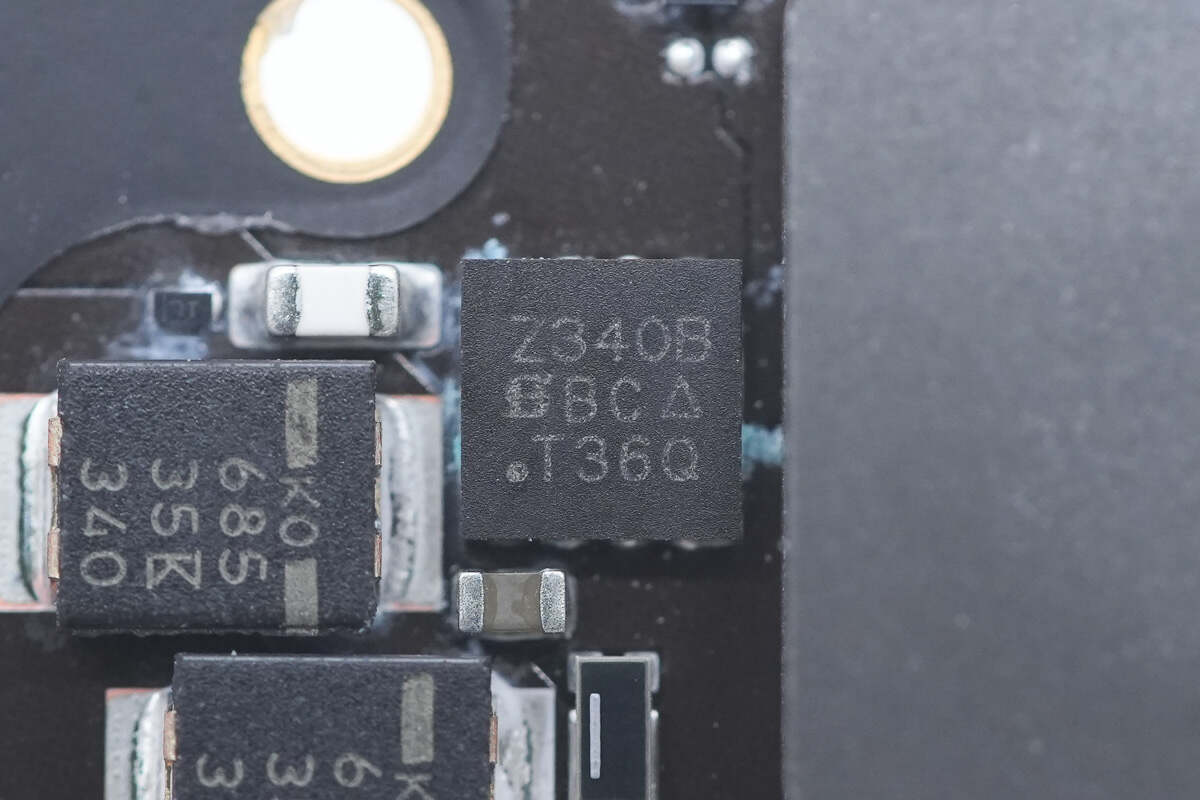
The MOSFET is from VISHAY and adopts PowerPAIR3*3 package. Model is SiZ340BDT. 30V.
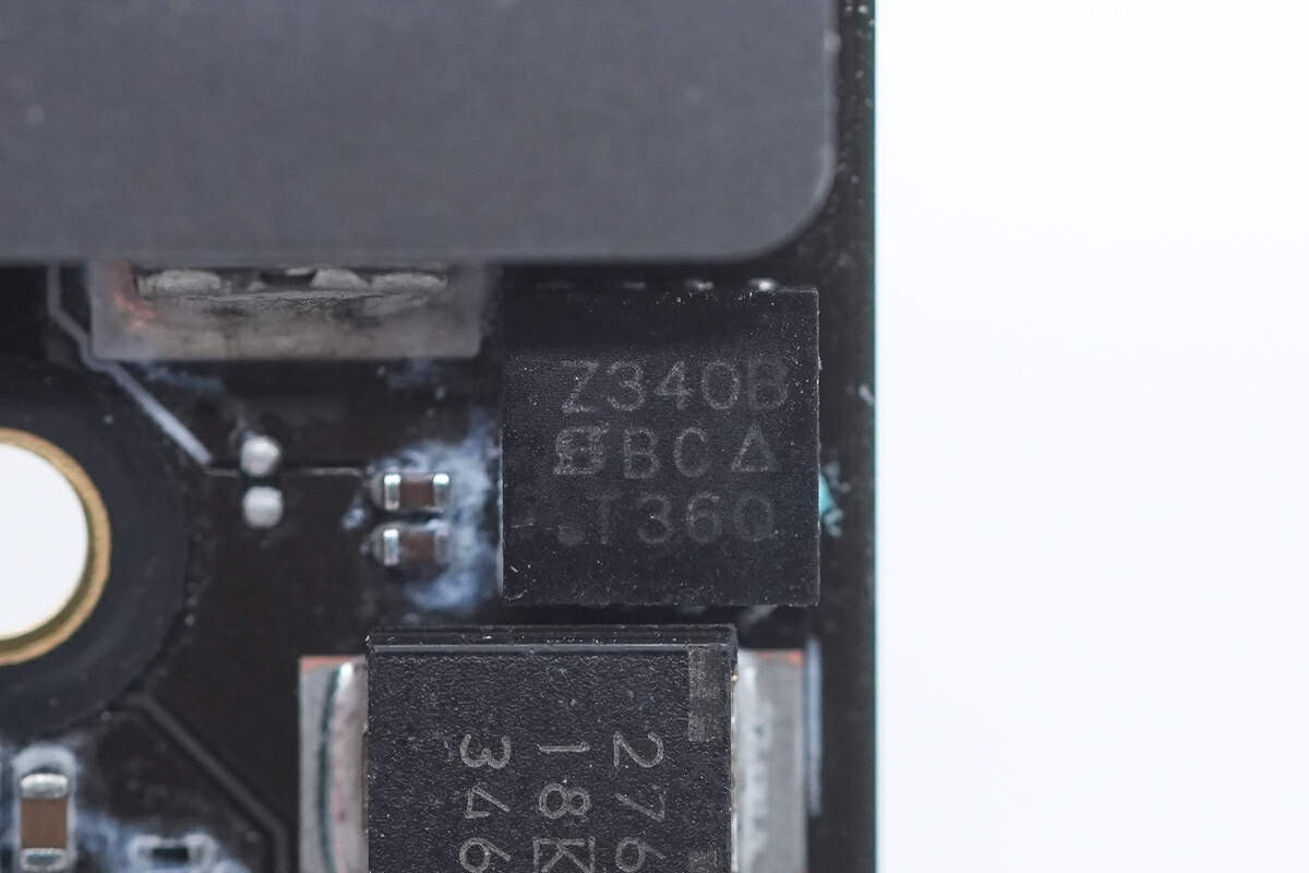
The other MOSFET is the same model as the previous one.
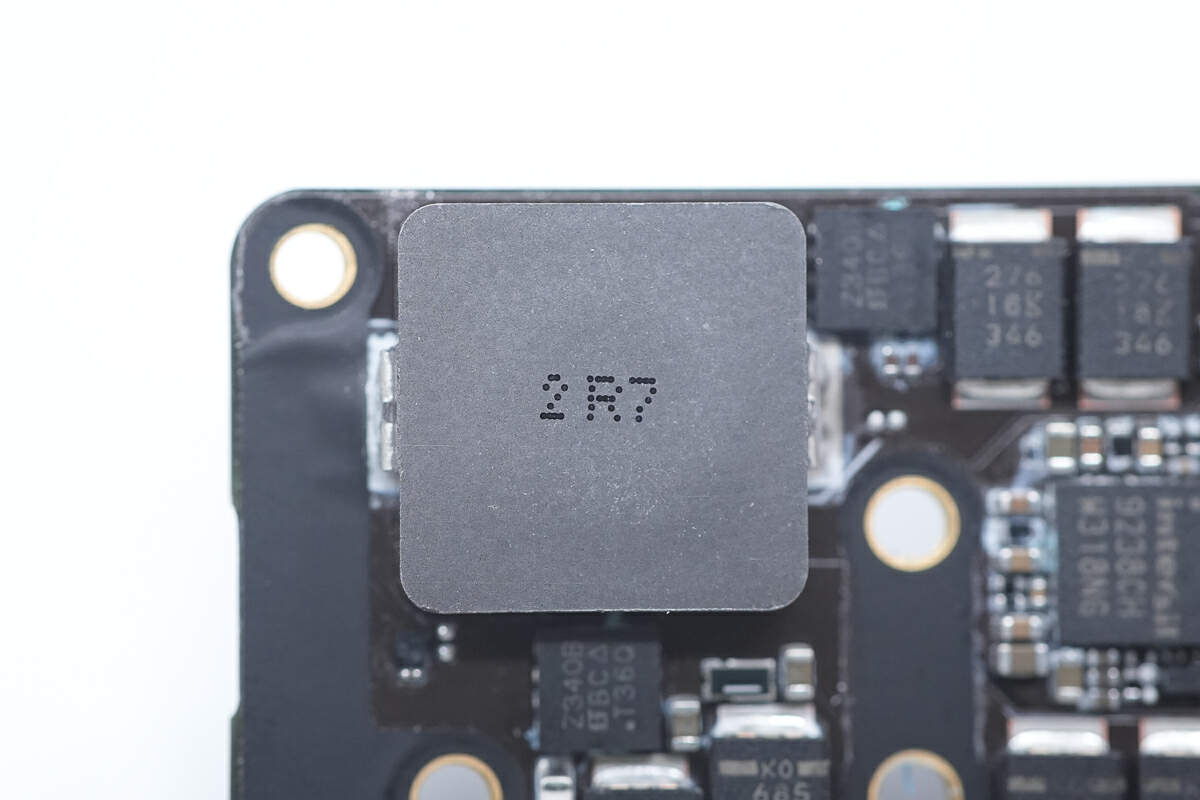
This is an alloy inductor. 2.7μH.
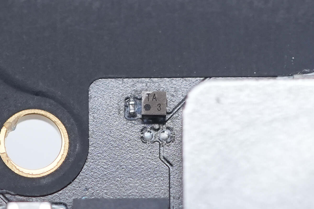
The temperature sensor marked with TA is from TI and adopts DSBGA4 package. It has I2C and SMBus ports. Model is TMP103A.
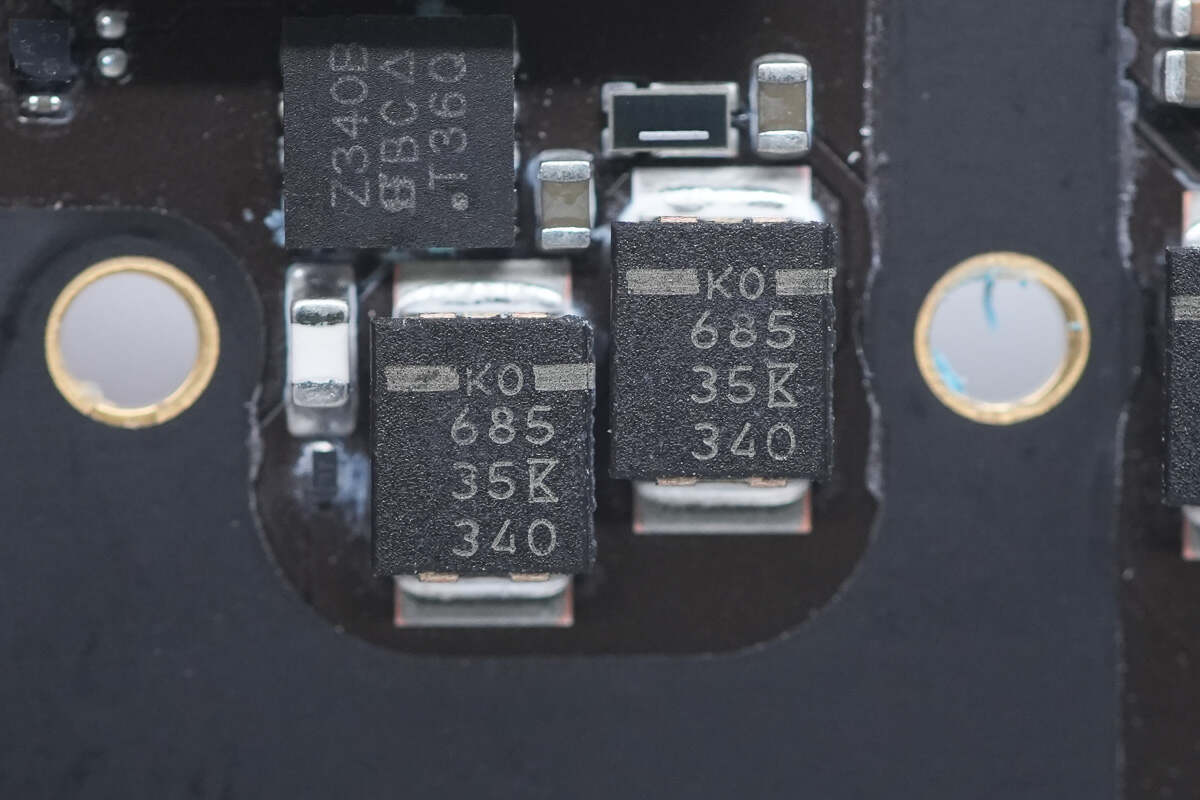
The tantalum capacitor for input filtering is from KEMET. 6.8μF 35V. There are 7 pieces in parallel, with a total capacity of 47.6μF.
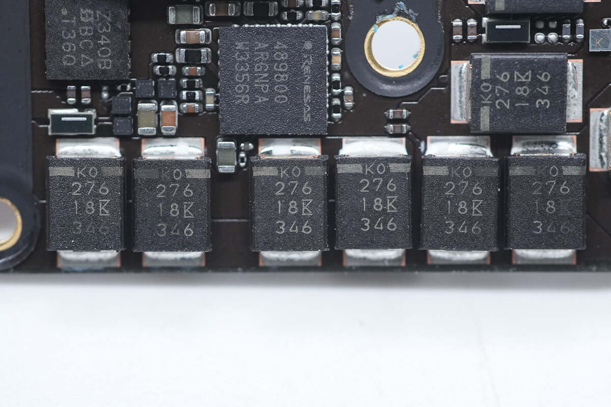
The tantalum capacitor for output filtering is also from KEMET. 27μF 18V. There are 12 pieces in total, with a total capacity of 324μF.
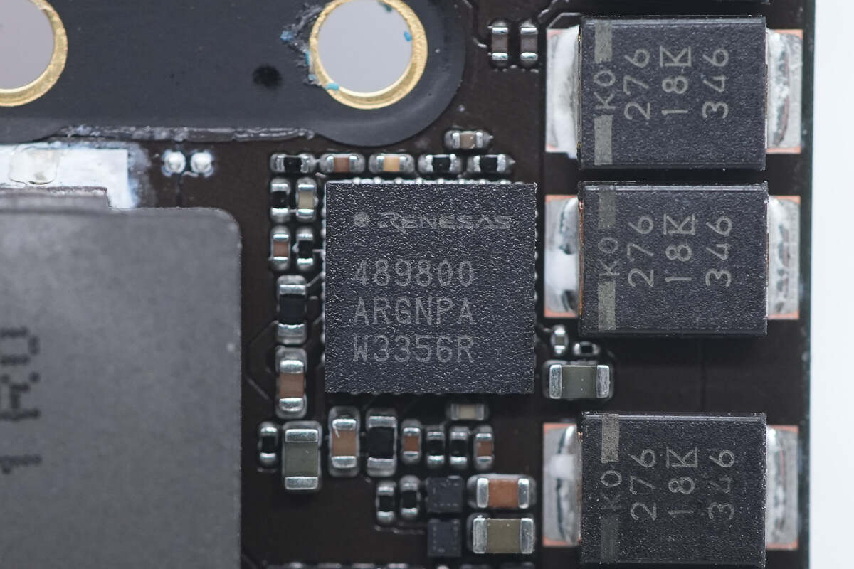
Another synchronous buck-boost controller is from RENESAS and adopts 4*4TQFN package. It supports an input voltage range of 3.8-23V and an output voltage of up to 21V. Model is RAA489800.
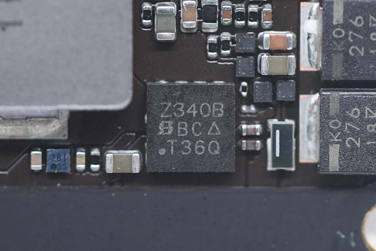
The MOSFET used for synchronous buck-boost voltage conversion is from VISHAY. Model is SiZ340BDT.
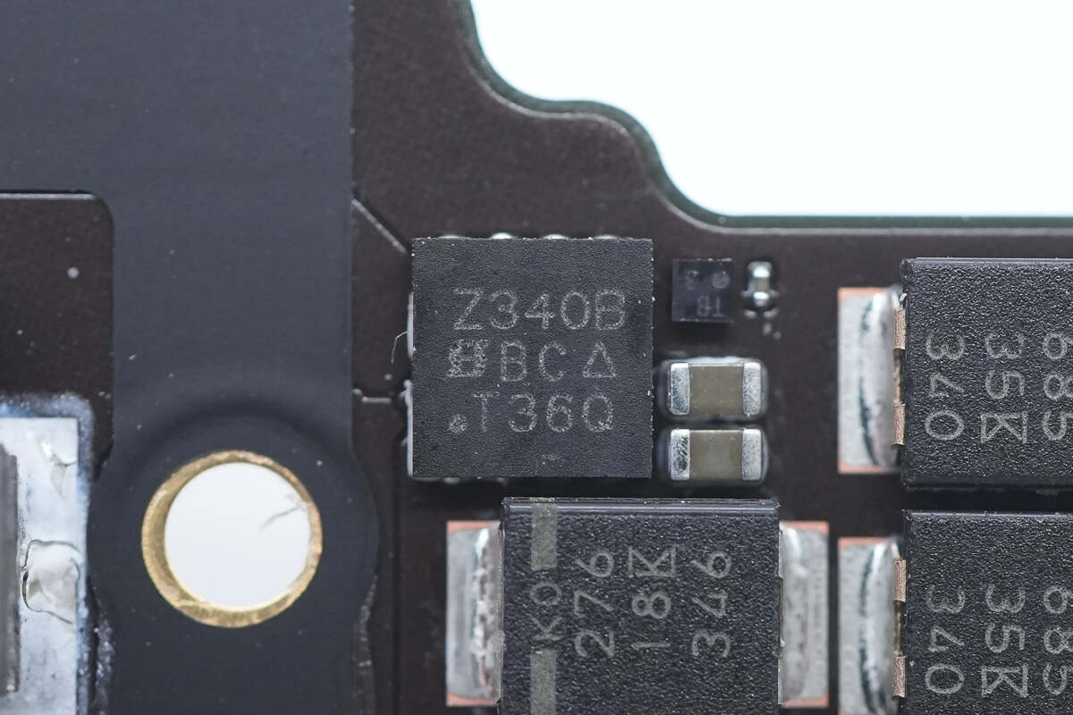
The other MOSFET is of the same model. The temperature sensor on the right side of the MOSFET used to detect the internal temperature is from TI. Model is TMP103B.
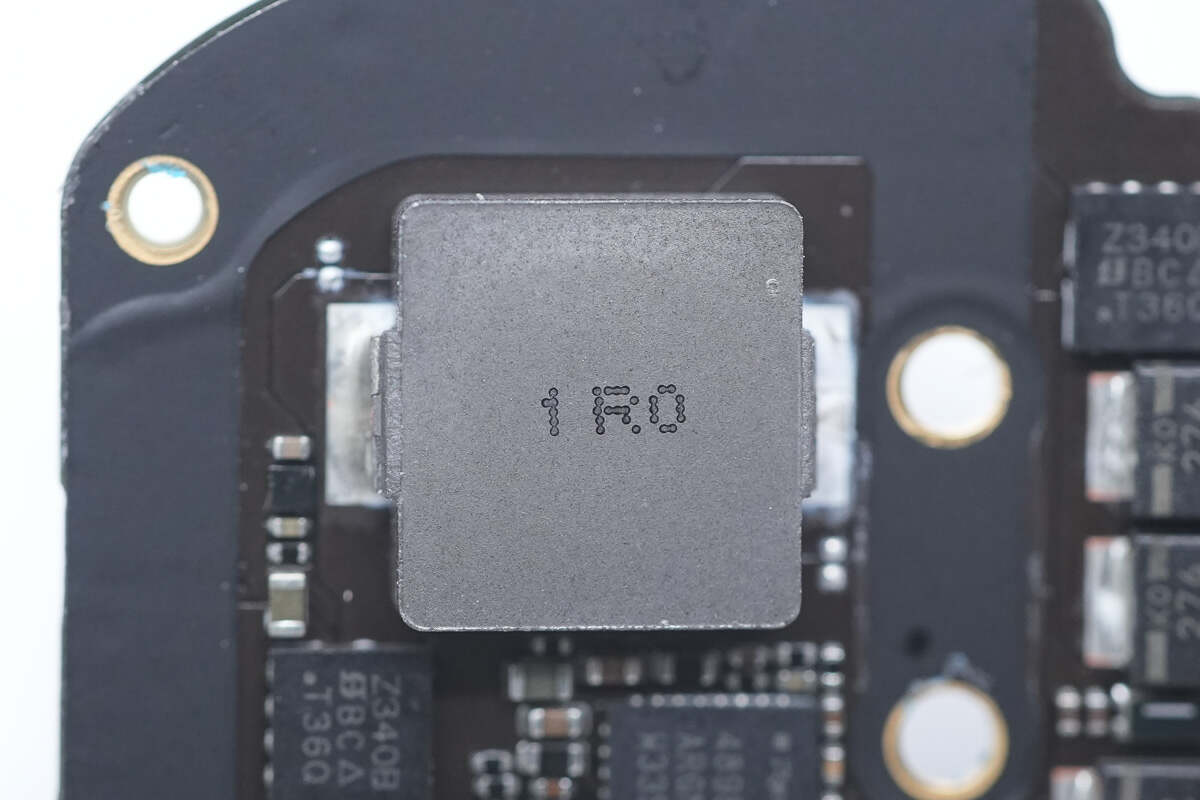
This alloy inductor is used for buck-boost voltage conversion. 1.0μH.
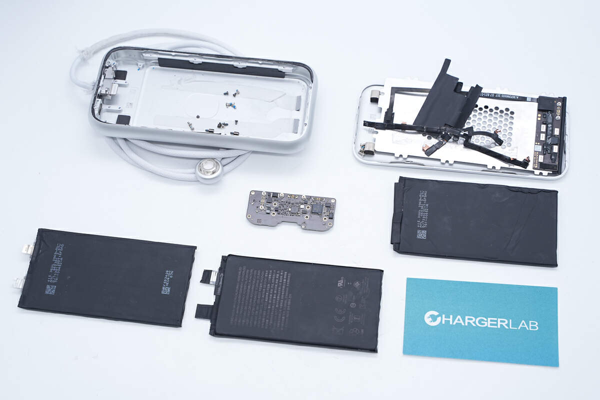
Well, those are all components of the Apple Vision Pro Battery.
Summary of ChargerLAB
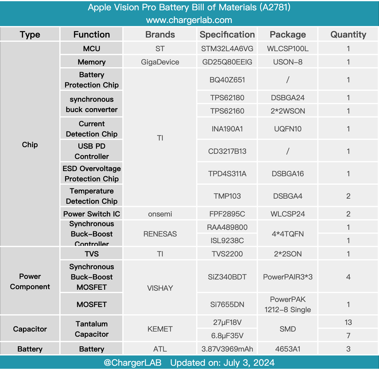
Here is the component list of the Apple Vision Pro Battery for your convenience.
The Apple Vision Pro Battery is made out of smooth, machined aluminum and comes with a woven power cable. It also has a USB-C port and an indicator light. Its model is A2781. It can support the output of 13V 6A. Its energy is 35.9Wh. It supports 5-20.3V input voltage and 3.3A maximum input current.
After taking it apart, we found the battery pack uses three cells. The battery pack is connected to the PCBA module via cables. The PCBA module is equipped with two synchronous buck-boost circuits, which are used for battery charging and buck-boost output respectively. The controller comes from RENESAS. Both synchronous buck-boost circuits adopt MOSFETs from VISHAY and are equipped with temperature detection chips for temperature monitoring and tantalum capacitors from KEMET for filtering. The battery pack has a built-in MCU from ST for overall control and memory from GigaDevice for configuration storage. Its PD controller comes from TI and uses a protection chip from TI to protect the USB-C port from electrostatic discharge.
The internal components are all from international first-line brands. The internal arrangement is compact, saving space and effectively reducing the size. Its workmanship is fine and reliable.
Related Articles:
1. How Fast Is Apple Vision Pro Charged? - ChargerLAB Compatibility 100
2. 9498mAh Battery Capacity | Deep Delve into Apple Vision Pro Battery
3. The Future is Here? A Compilation of Potential Accessories for Apple Vision Pro


