Introduction
ChargerLAB have taken apart lots of different power adapters from Apple, but they are all new products released in recent years. And today, let's go back to 2006 and see what kind of power adapter Apple released that year.
This is an original 110W power adapter for Mac mini from early 2006 to late 2009. The power supply was not integrated inside the Mac mini at that time. Just like most gaming laptops, it was independent outside the device. So today we're going to take it apart and reveal its internal components and build quality. Will it have the same high-quality workmanship as today's Apple products? Let's find out.
Product Appearance
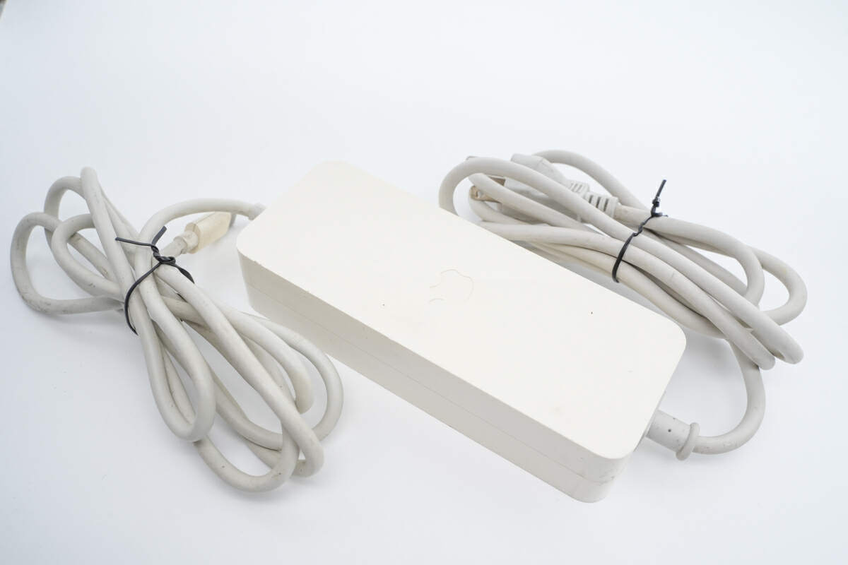
The white plastic shell of this Apple Mac mini power adapter slightly turned yellow due to oxidation.
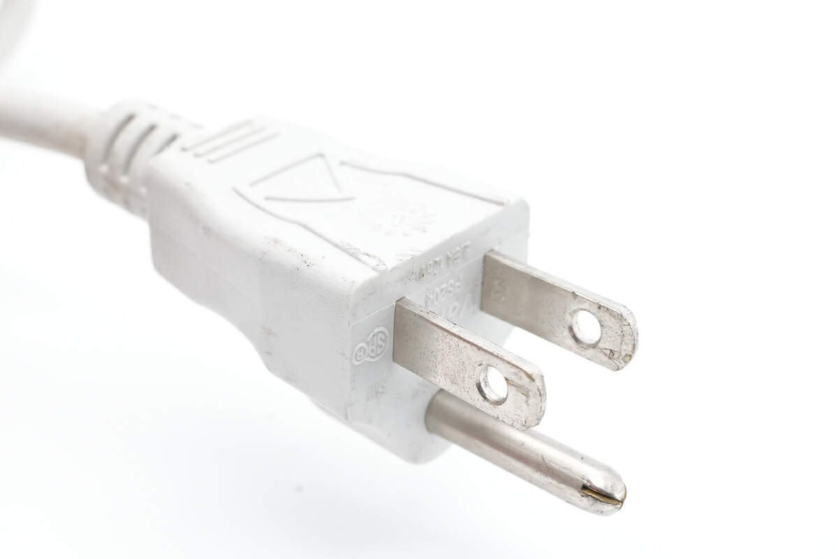
The input prongs are grounded.
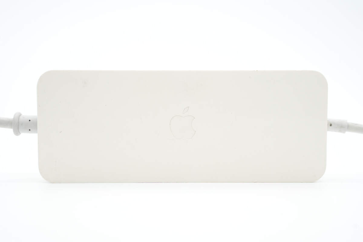
The classic Apple logo is engraved in the center of the adapter.
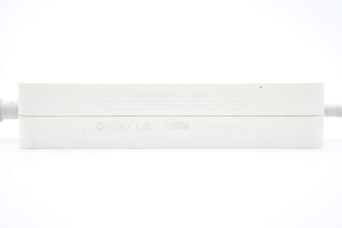
And all specs info are printed here.
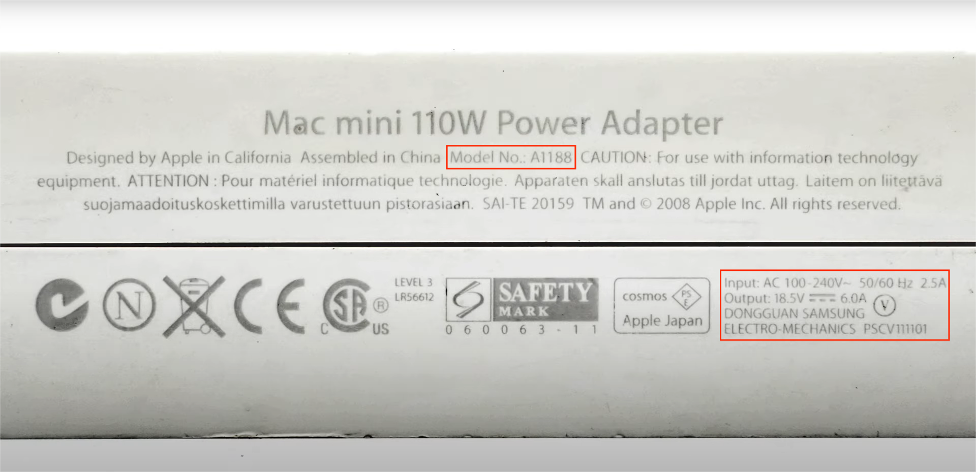
Model is A1188. It supports input of 100-240V~50/60Hz 2.5A, and the output can be up to 18.5V 6A 110W. It has passed CE certification and is manufactured by Dongguan Samsung Electro-Mechanics Co Ltd.
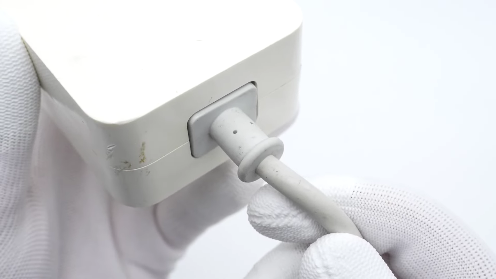
Like traditional power adapters, the input power cord can be detachable.
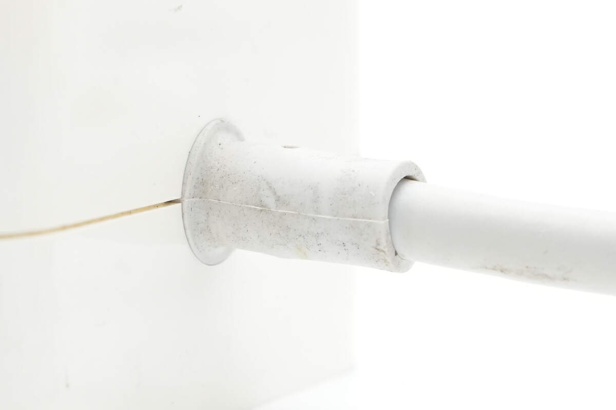
And the joint between the output cable and the power adapter has been reinforced.
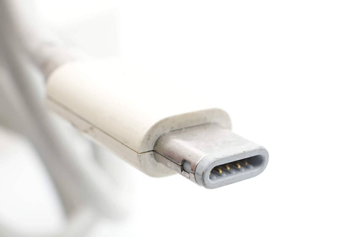
The output connector looks like USB-C, but everyone knows that there was no USB-C connector back then.
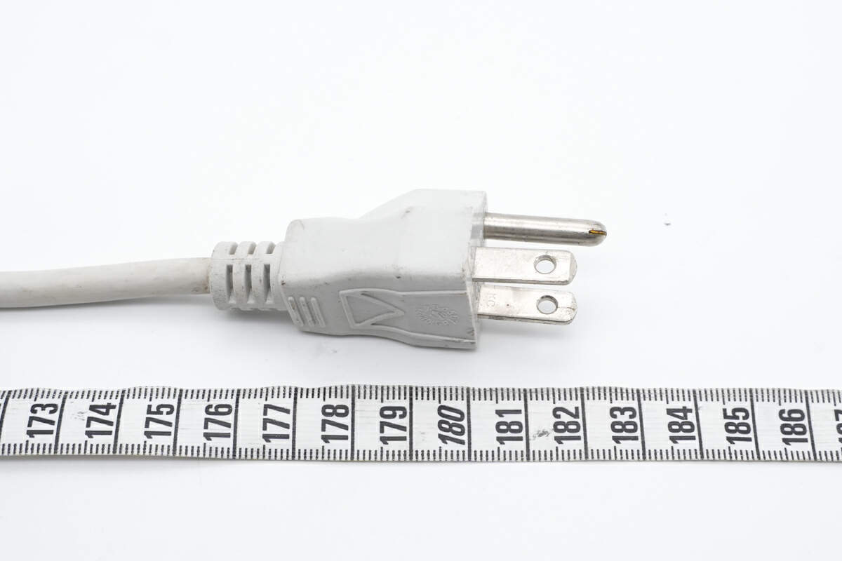
The length of the input power cord is about 1.8M (5' 10.87'').
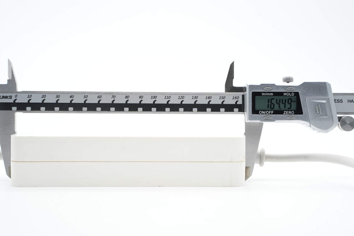
The length of this power adapter is about 164.5mm (6.48 inches).
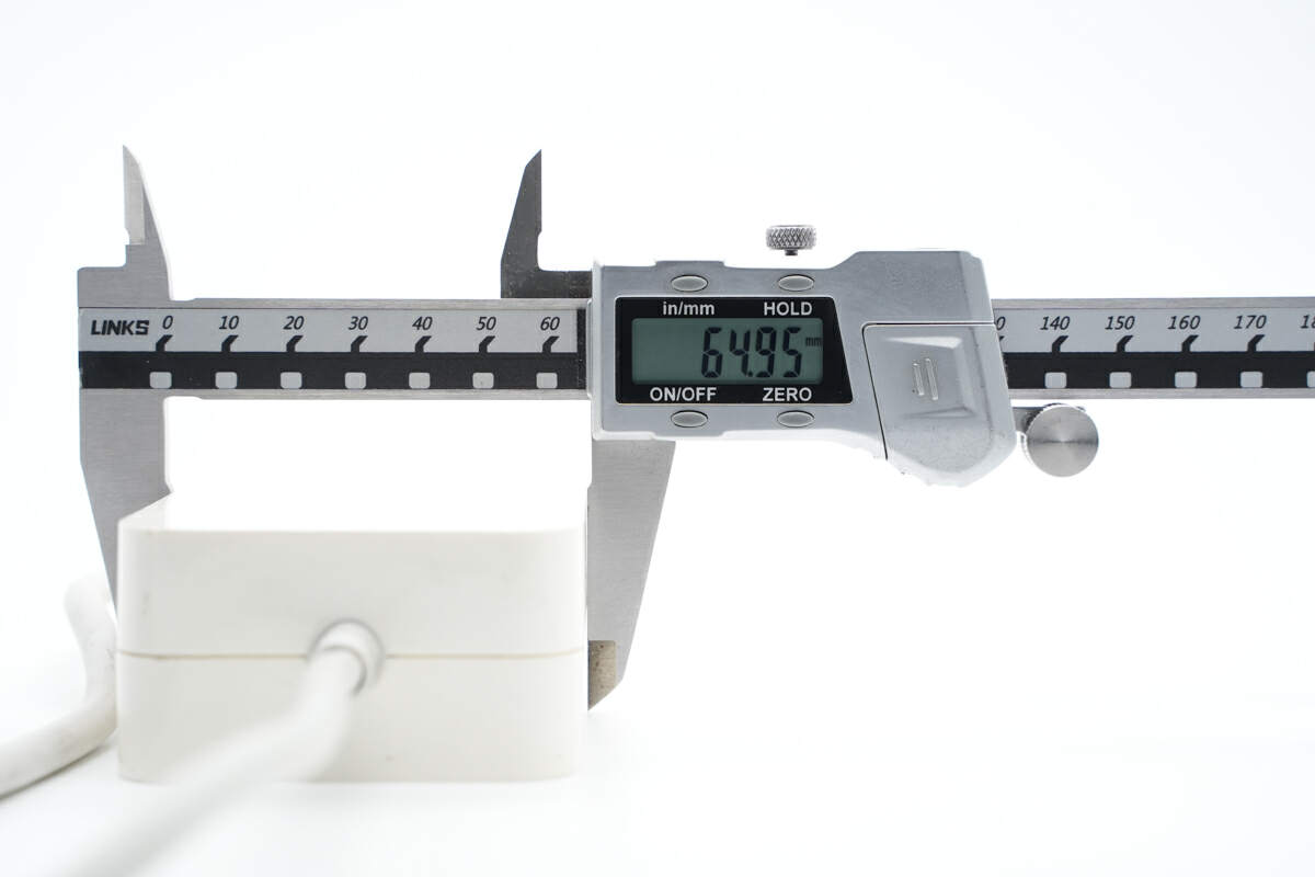
The width is about 65mm (2.56 inches).
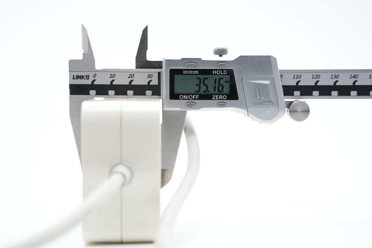
And the height is about 35mm (1.38 inches).
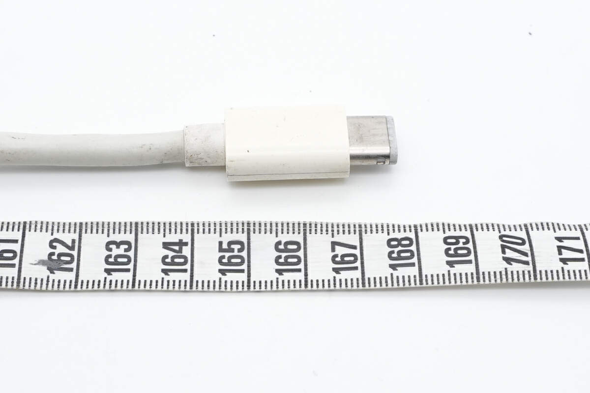
And the output cable is about 1.7M (5' 6.93''), so the total length exceeds 3.5M (11' 5.8''), which is more than enought for daily use.
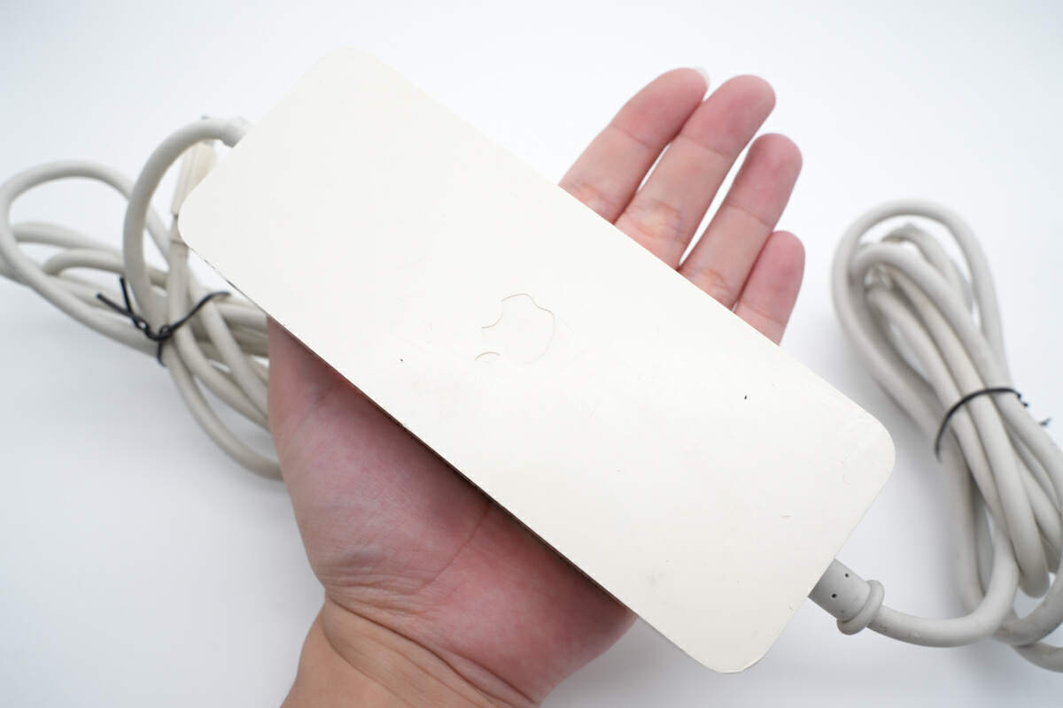
This is how it looks like on my hand.
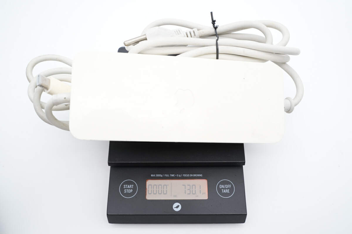
And the total weight is about 730g (25.75 oz).
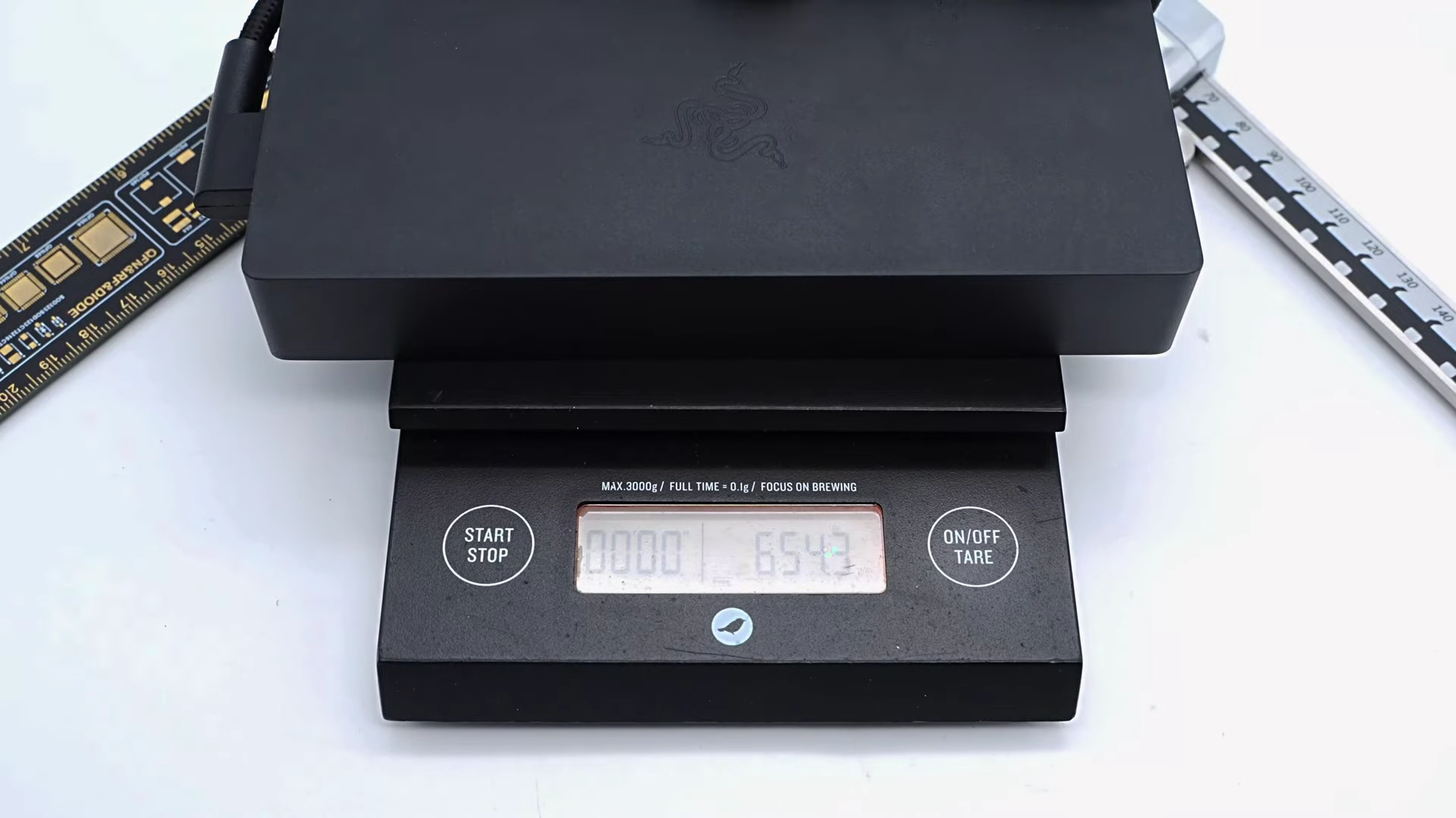
It's hard not to be amazed at the pace of technological progress. after all, this 110W power adapter, despite being significantly slower, is actually heavier than the Razer Blade 280W GaN Power Adapter we took apart half a year ago.
Teardown
Since we do not have an old Mac mini to test, we'll take it apart directly to see what differences are inside compared to recent Apple power adapters.
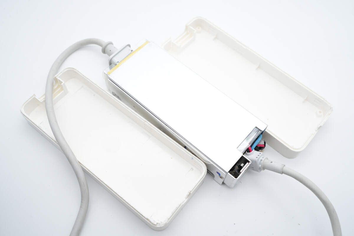
Using a spudger, you can easily pry along the gap to remove the white plastic case, and the internal metal cover is definitely Apple's traditional design.
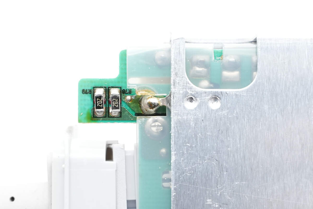
It's fixed with screws and soldered to the PCB.
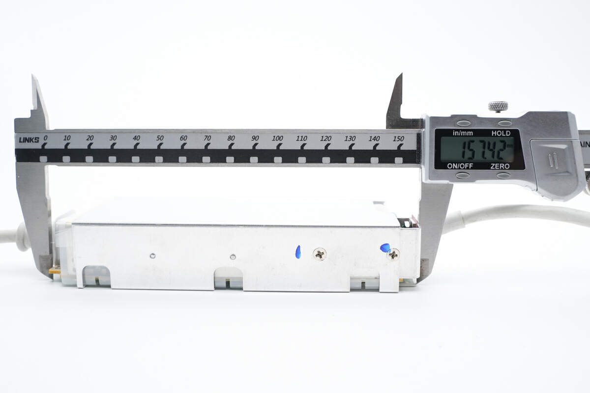
The length of the PCBA is about 157.4mm (6.20 inches).
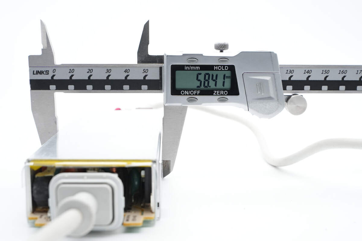
The width is about 58.4mm (2.30 inches).
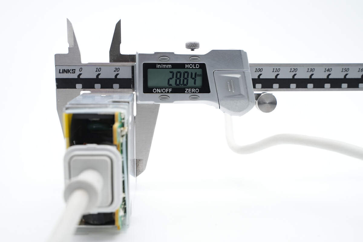
And the height is about 28.8mm (1.13 inches).
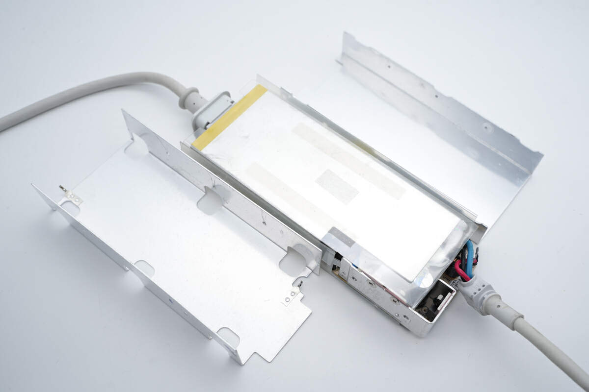
After removing the metal heat sink, a layer of Mylar sheet is under it.
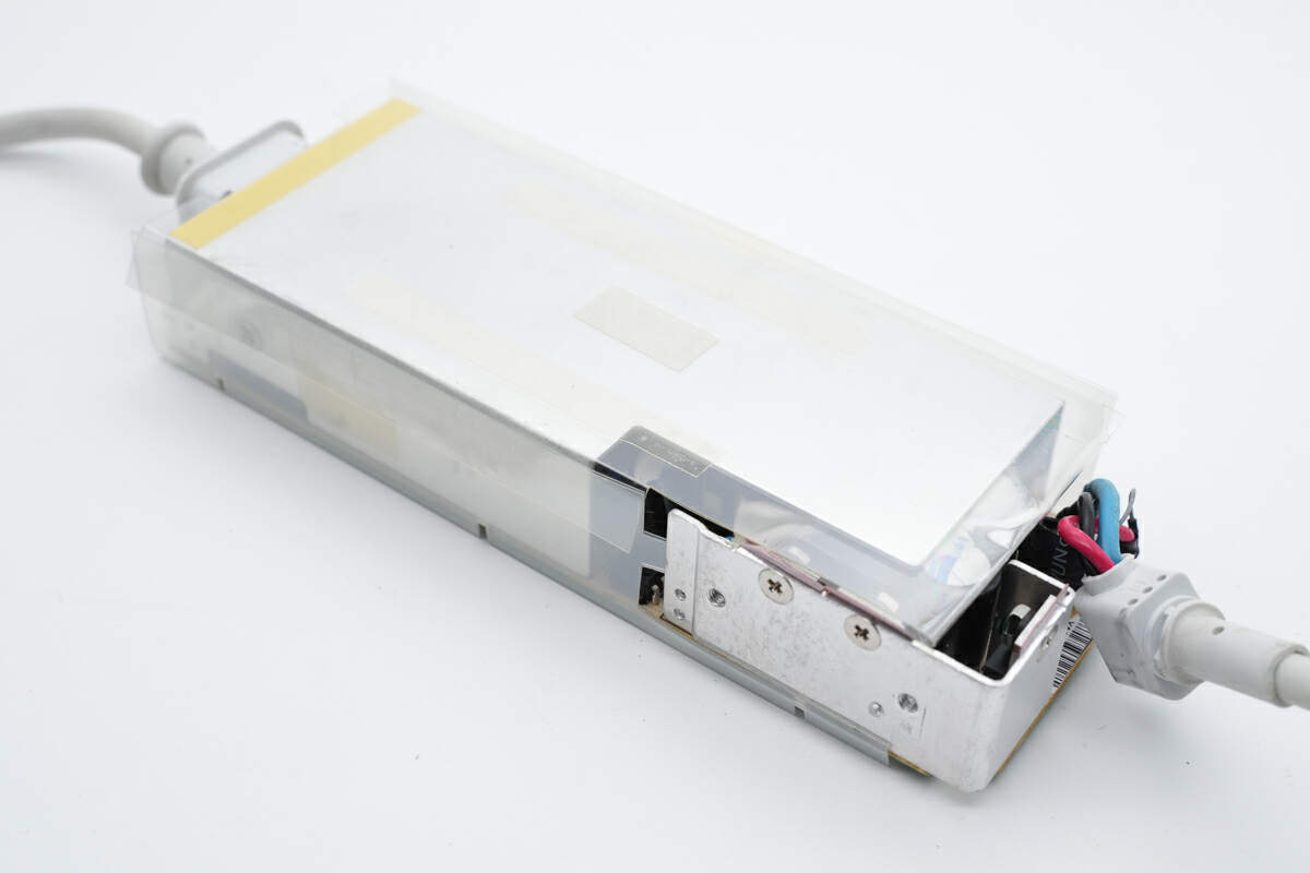
You can see the Mylar sheet covers most of the PCB.
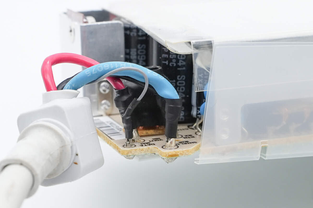
The red, black and blue wires are connected to the input end of the PCB.
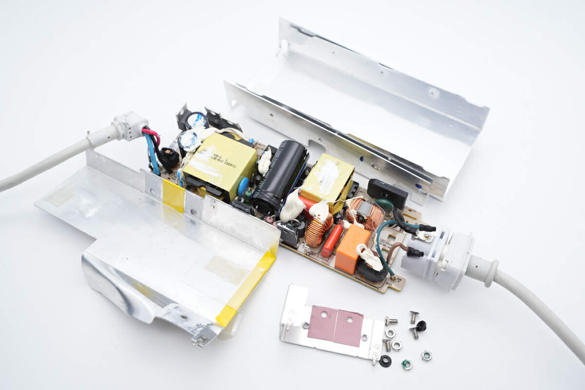
Remove all the metal heat sinks for a better view.
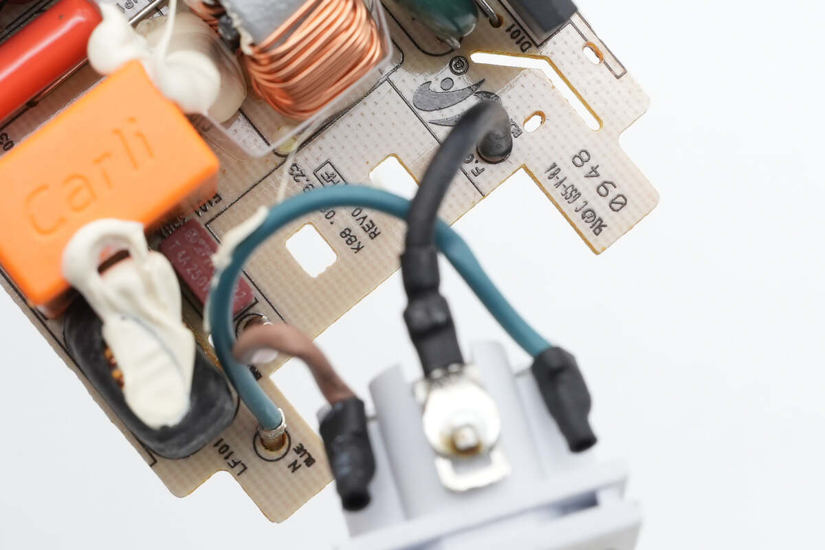
The socket of the input end is connected to the PCB by three wires.
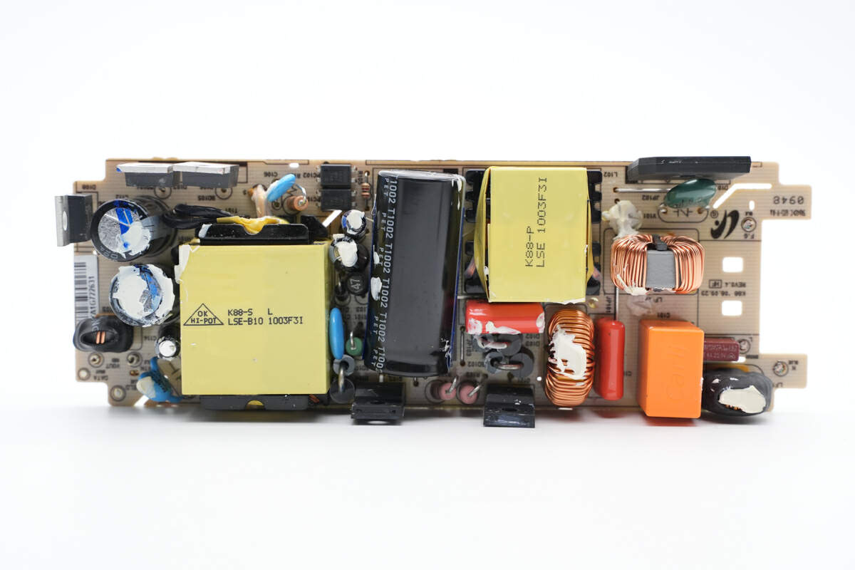
Let's take a closer look. Unlike the Apple chargers we've taken apart, it has a brown PCB instead of a black one, and those components are relatively sparse.
The fuse, EMI filter circuit, bridge rectifier, PFC boost inductor, high voltage filter capacitor, and transformer are on the front of PCBA module.
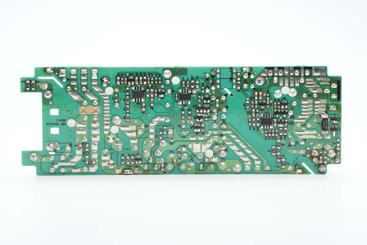
The back of the PCB is green, and the PFC controller, flyback controller and feedback control chip are on it.
We found it adopts flyback topology and has a PFC circuit. The Schottky diode inside can rectify the current, and the output voltage can be regulated through the optocoupler.
Let's start from the input end to introduce those old components.
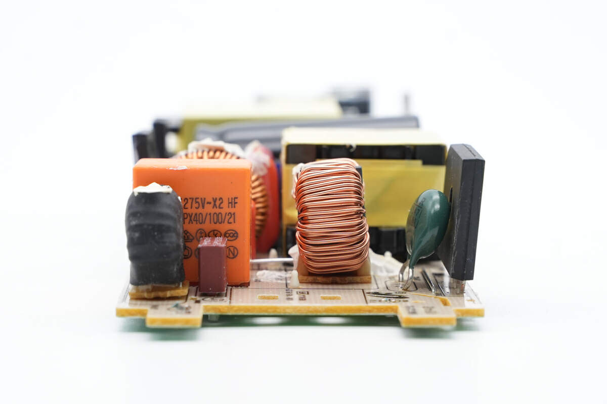
The fuses, common mode choke, safety X2 capacitor, varistor and bridge rectifier can be found at the input end.
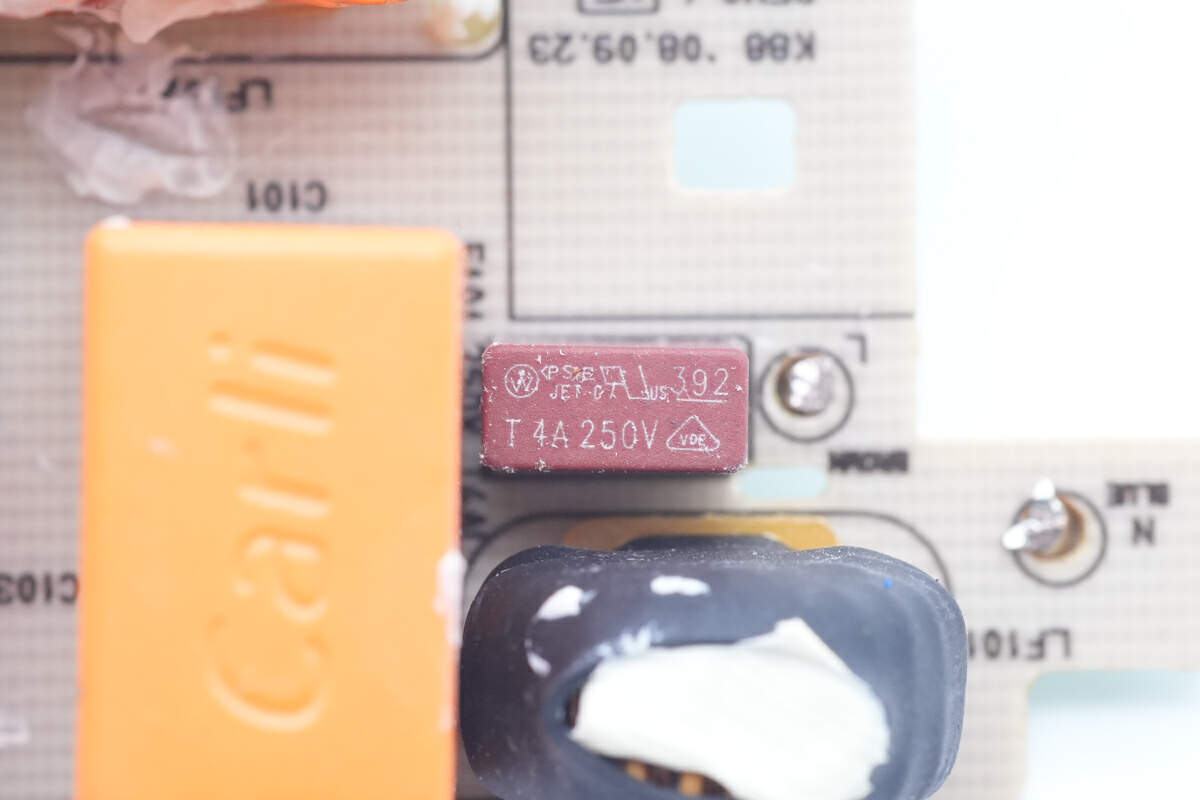
The input fuse is from Littelfuse 392 series. 4A 250V.
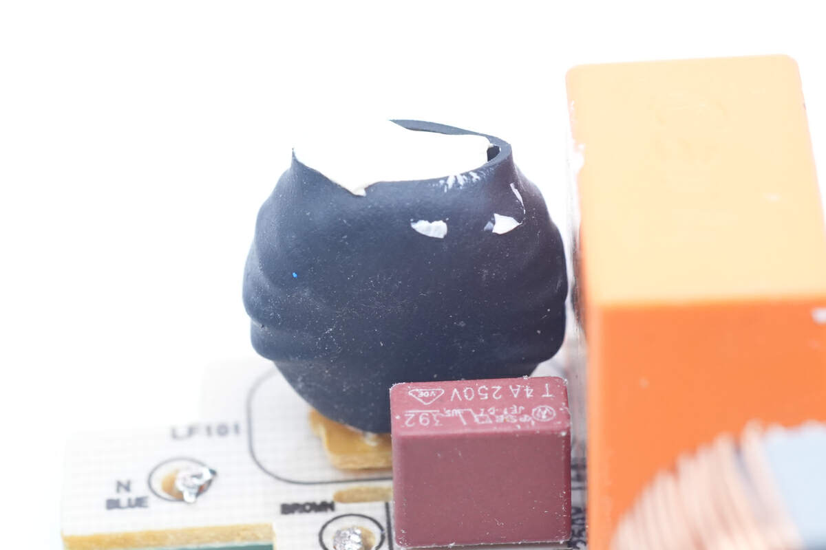
The common mode choke is fixed next to the fuse and is insulated with heat-shrinkable tubing.
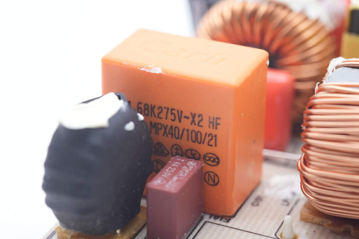
The safety X2 capacitor is from Carli with a capacity of 0.68μF.
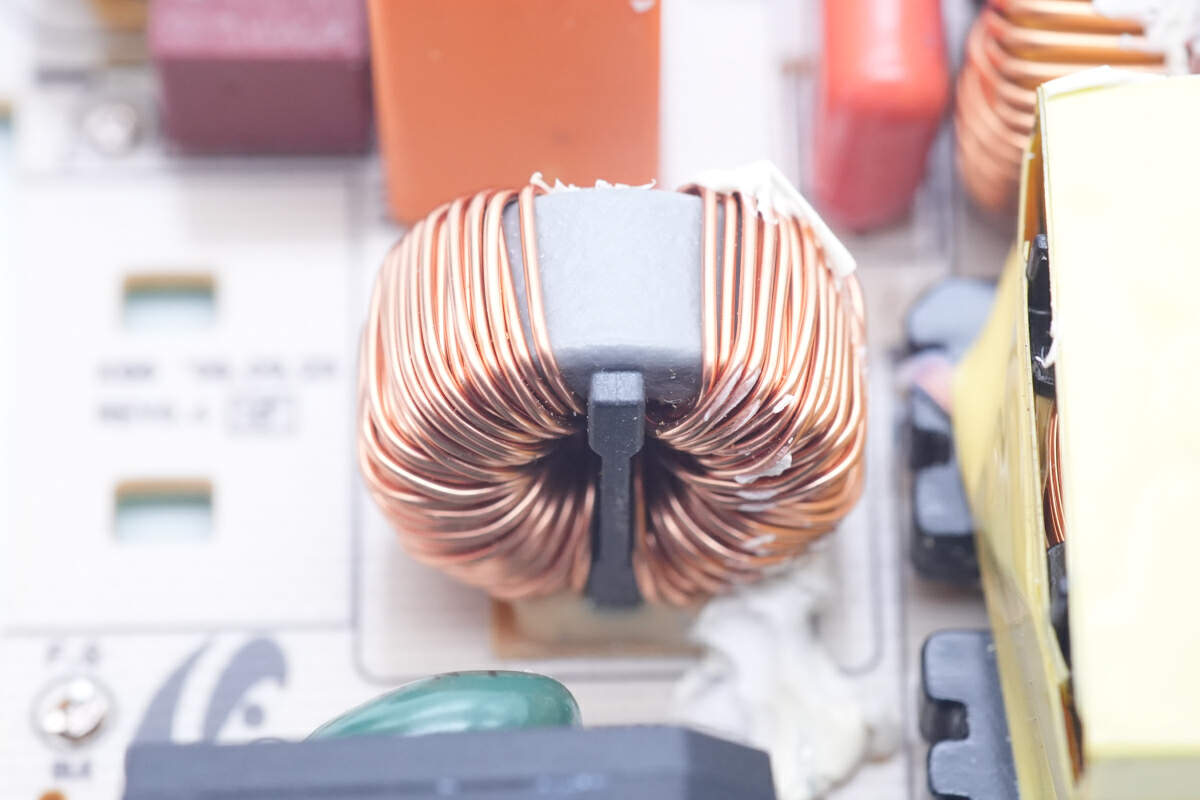
The second common mode choke is larger than the first one, and it's not insulated with heat-shrinkable tubing.
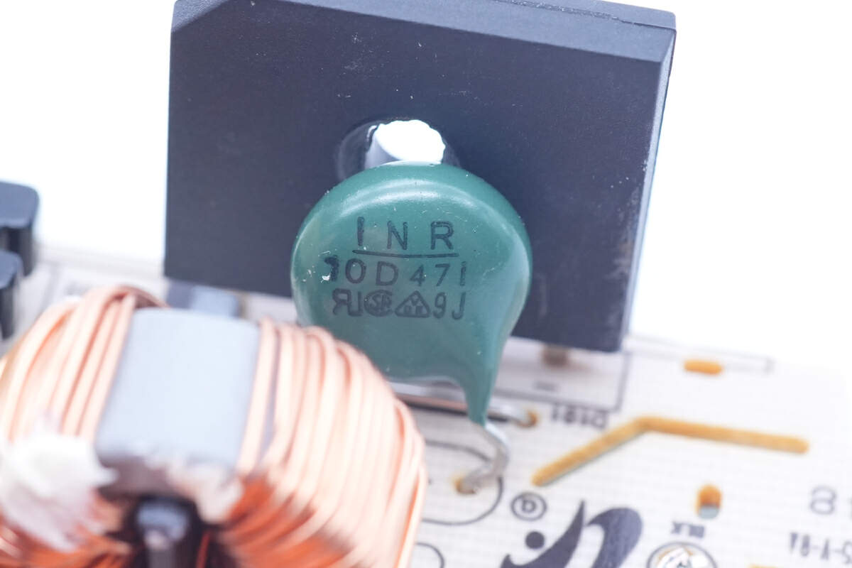
The 10D471 green varistor is used for overvoltage protection.
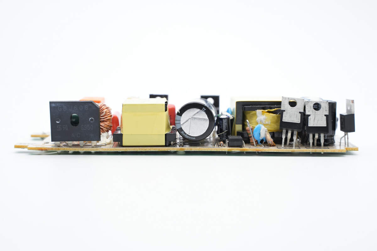
Moving on to this side of PCBA, we can find the bridge rectifier, PFC boost inductor, high voltage filter capacitor, feedback optocoupler and Schottky diode.
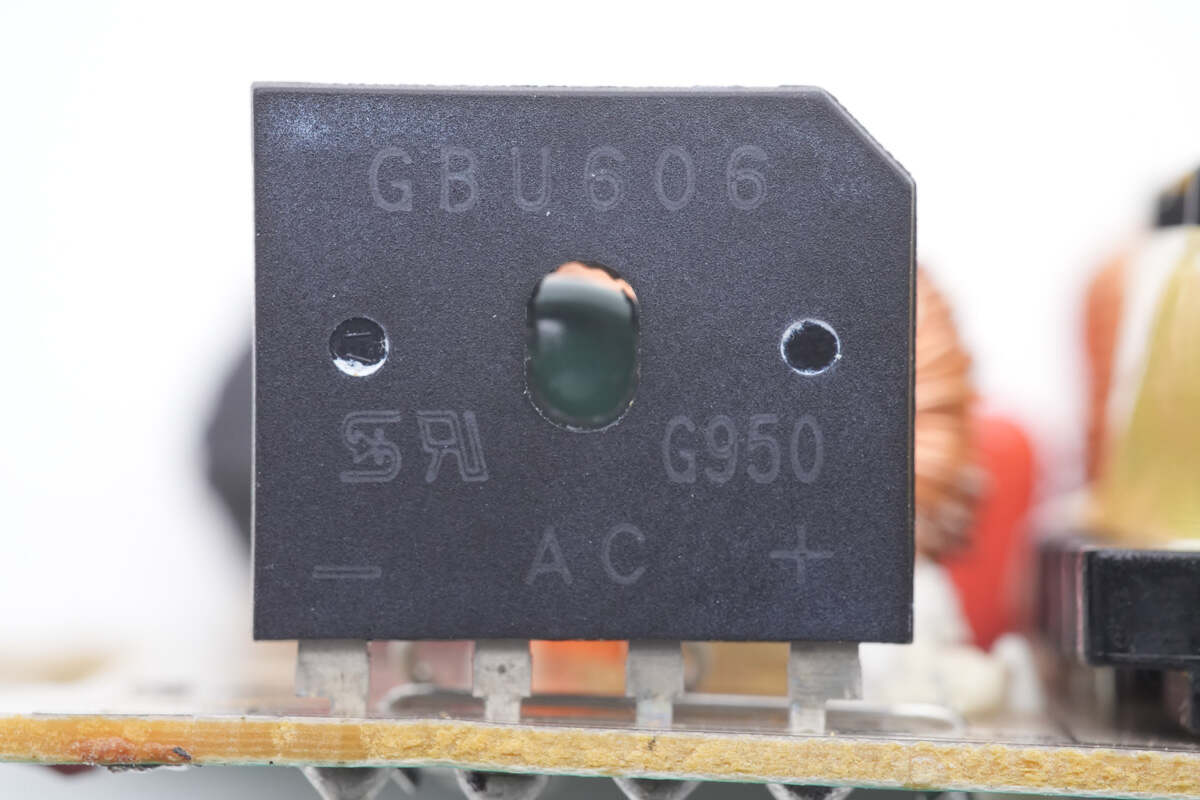
The bridge rectifier marked with GBU606 is used to rectify the AC into pulsed DC for the PFC circuit.
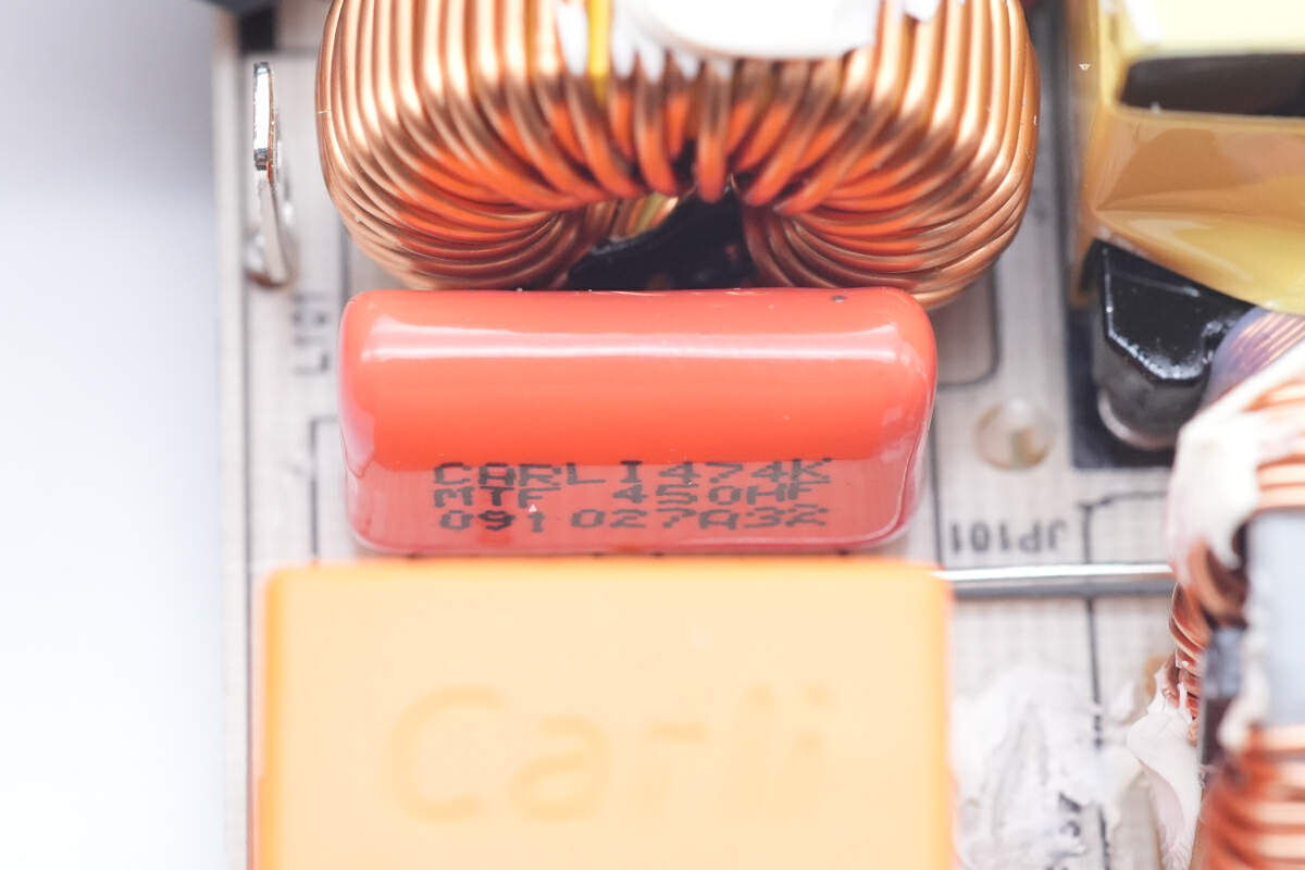
The film capacitor is from Carli. 0.47μF.
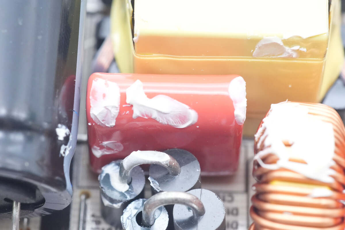
Another red film capacitor is used for filtering.
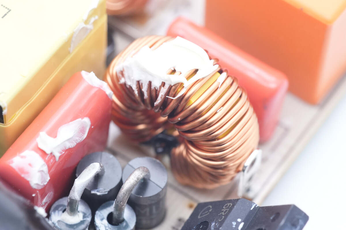
The toroidal-core inductor is between two film capacitors, used for output filtering.
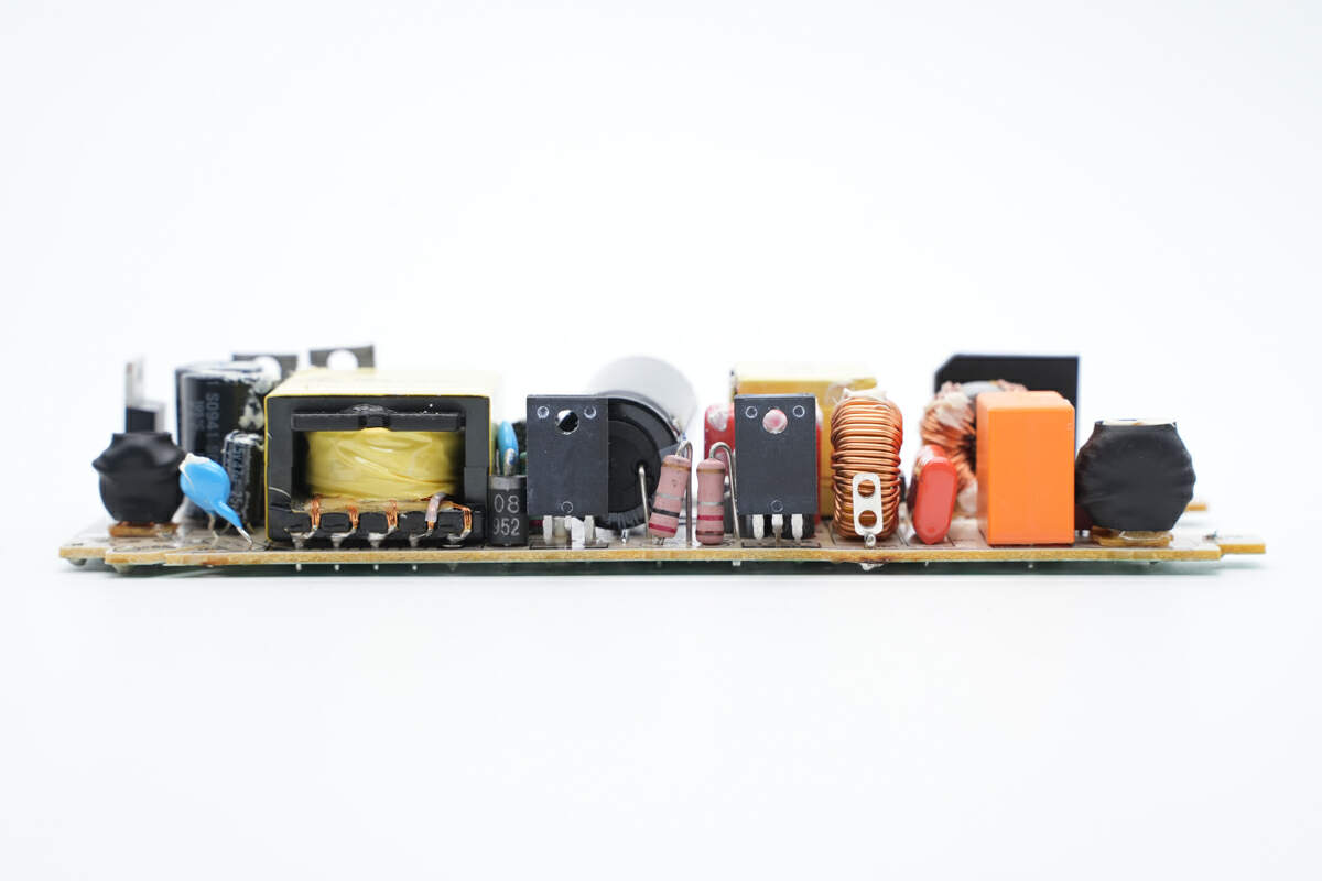
Next is the other side, we can see the transformer, flyback MOSFET and PFC MOSFET.
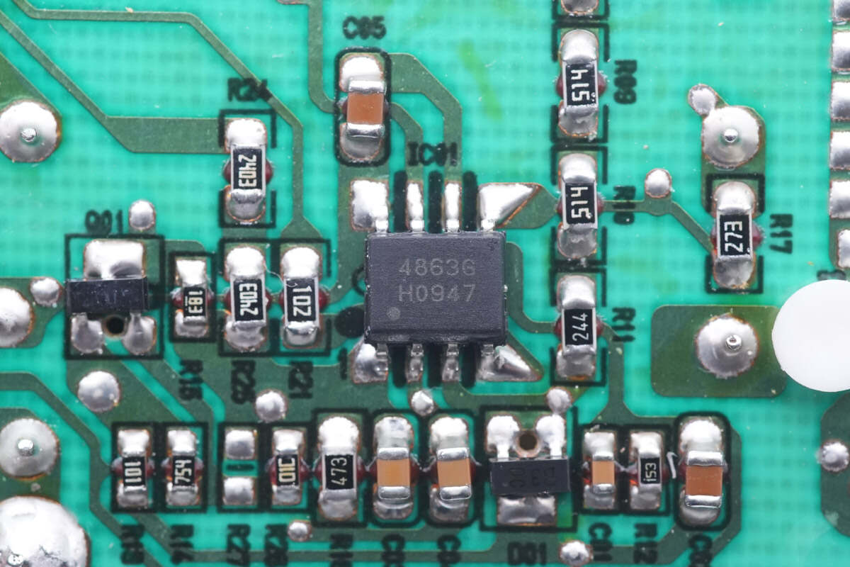
The PFC controller is from Infineon, model TDA4863G, which works in DCM mode. It supports output overvoltage and undervoltage protection.
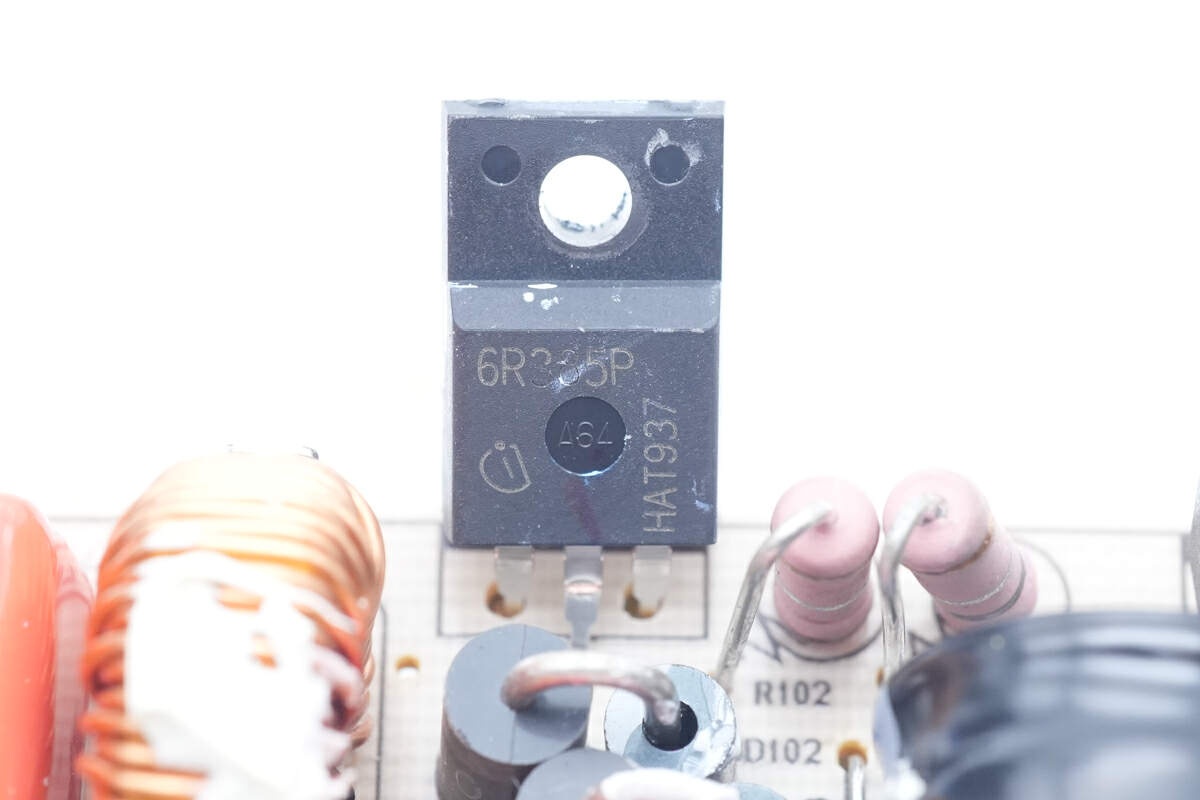
The primary MOSFET is from Infineon and adopts TO220FP package. Model is IPA60R385CP. 650V, 385mΩ.
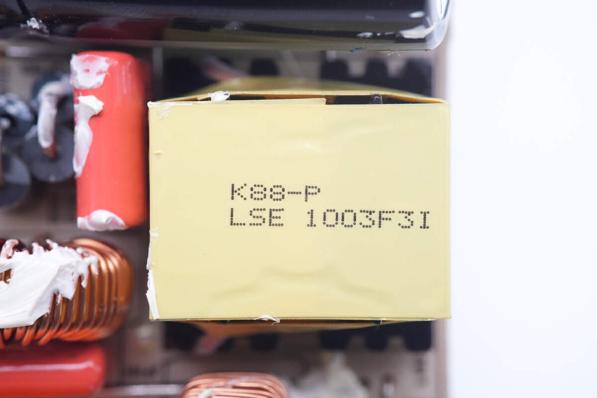
The PFC boost inductor is tightly wound and insulated with yellow tape.
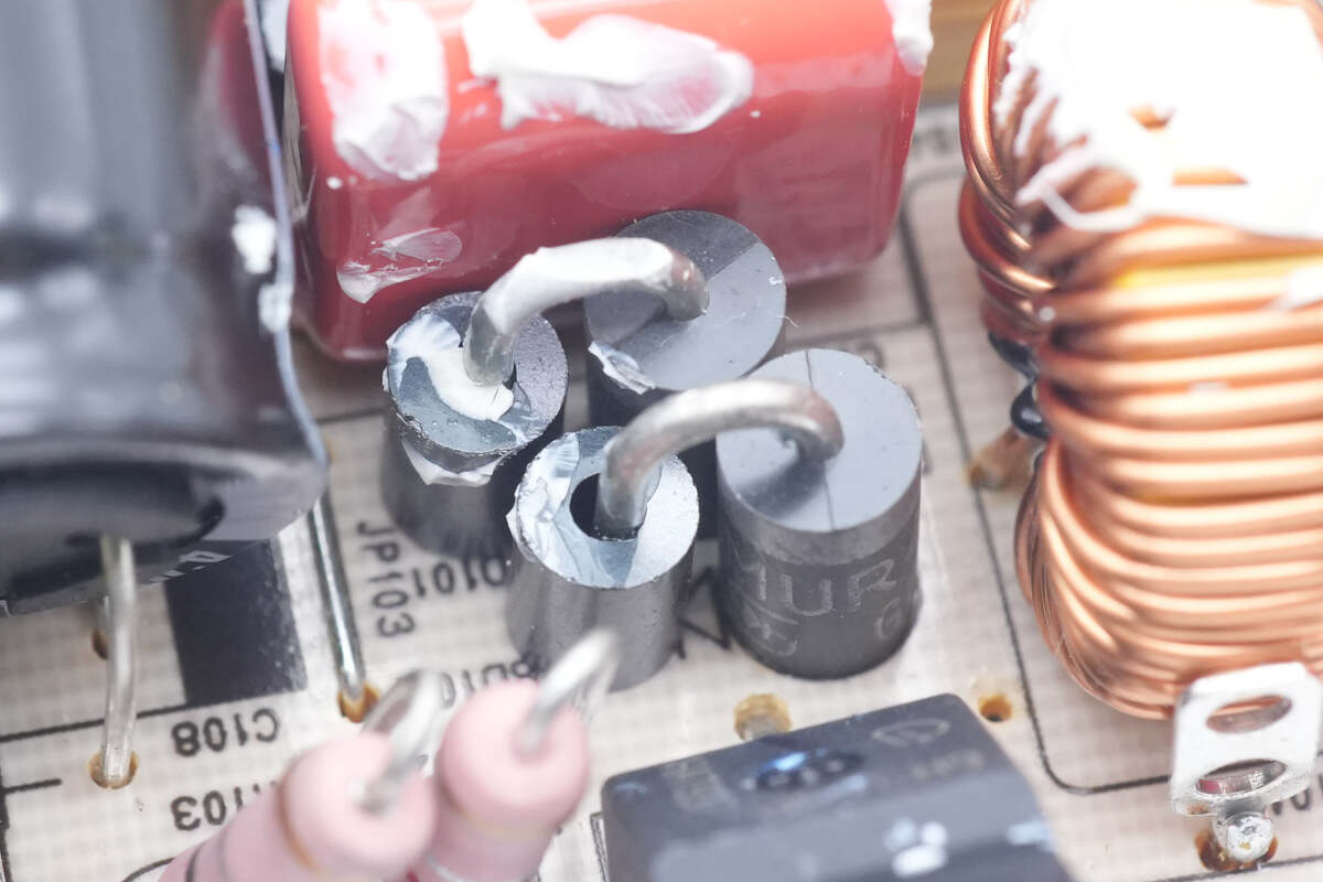
Two fast recovery diodes are used for PFC rectification, and the magnetic ferrite can suppress high-frequency interference.
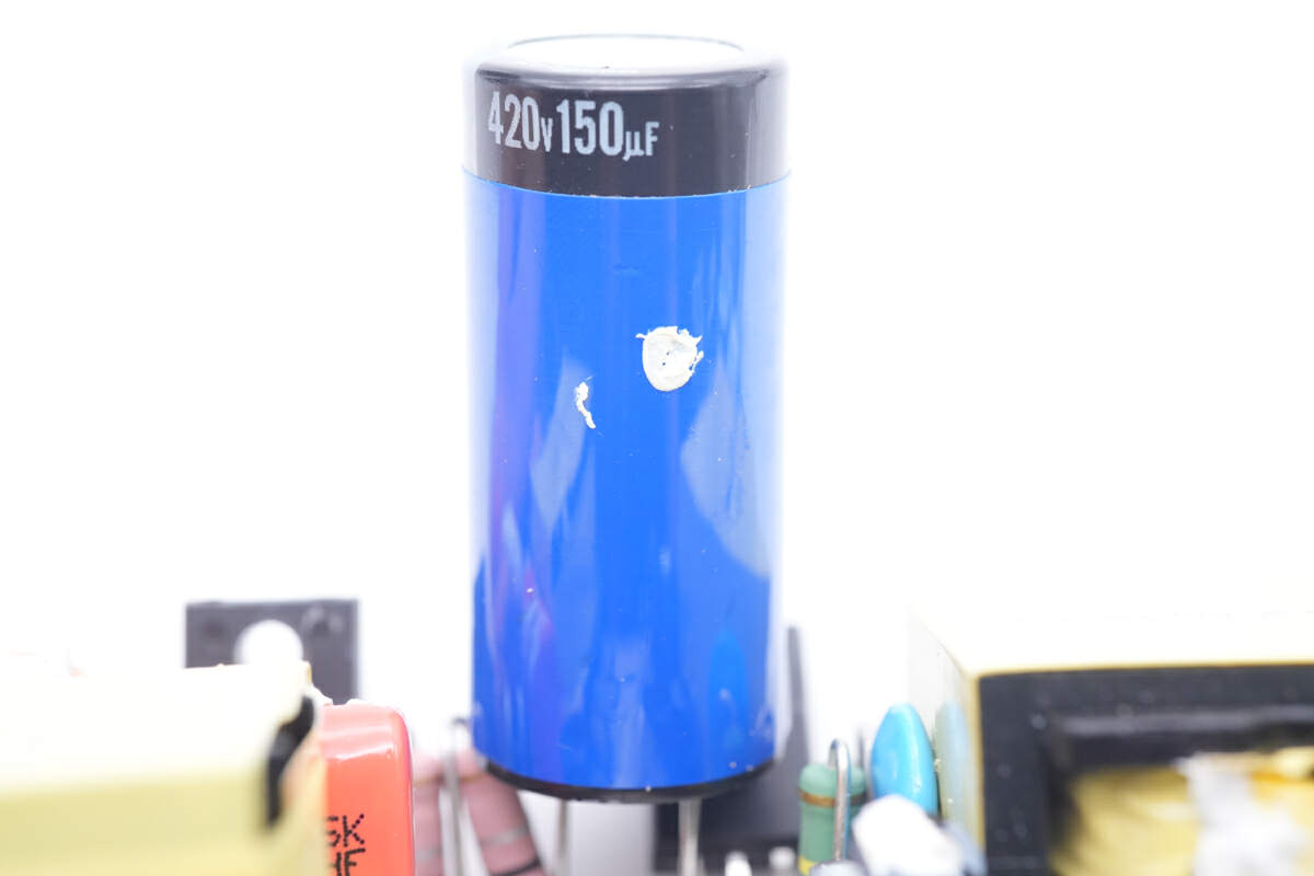
The high voltage electrolytic capacitor is insulated with blue tape.
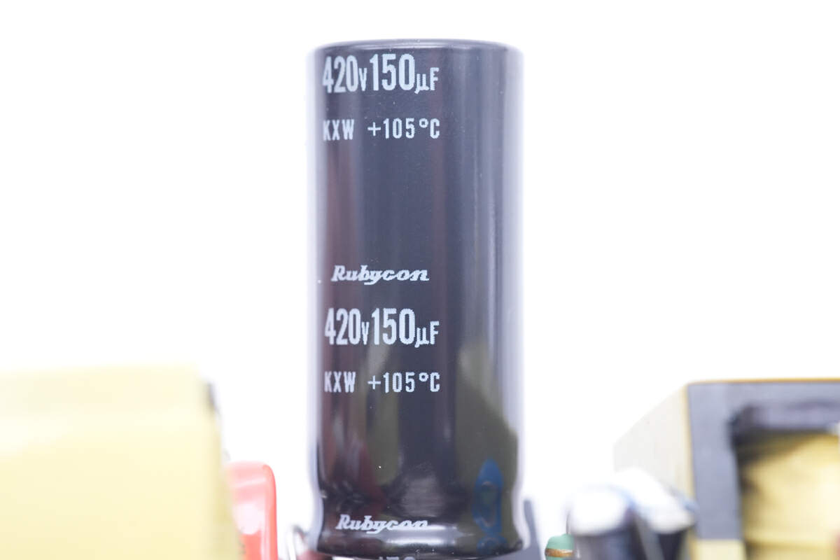
Tear it off. It is from Rubycon KXW series. 420V 150μF.
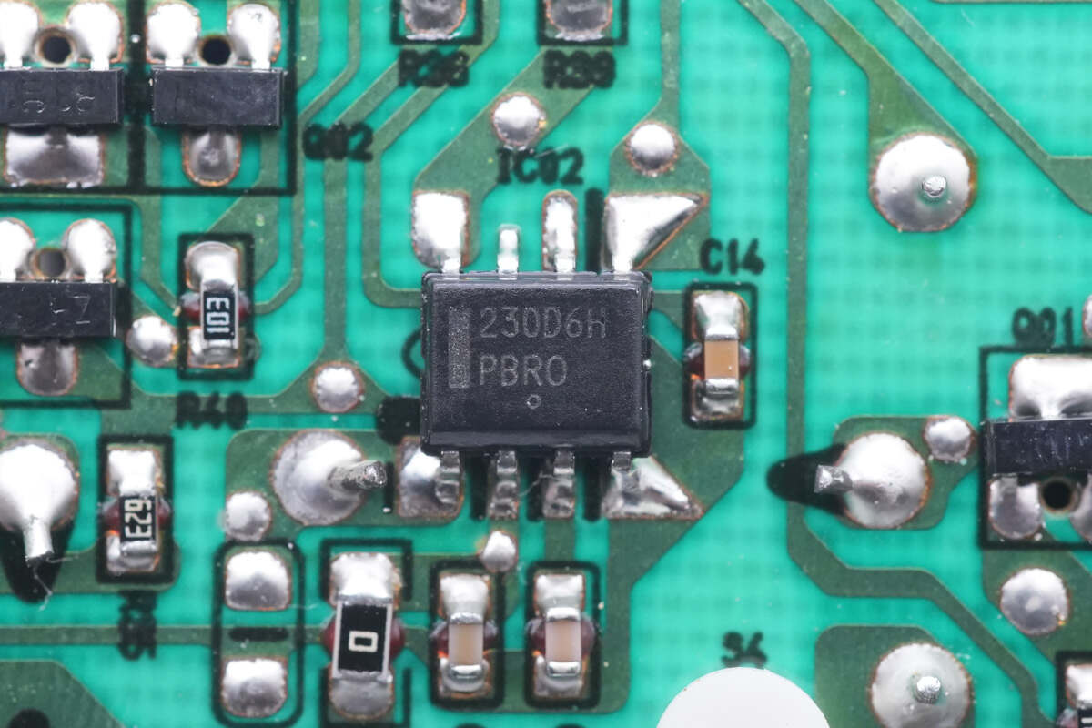
The master control chip is from ON Semiconductor. It's a high-performance PWM controller with low standby power consumption. It integrates high-voltage start, PFC control, soft start and various protection functions. The model is NCP1230.
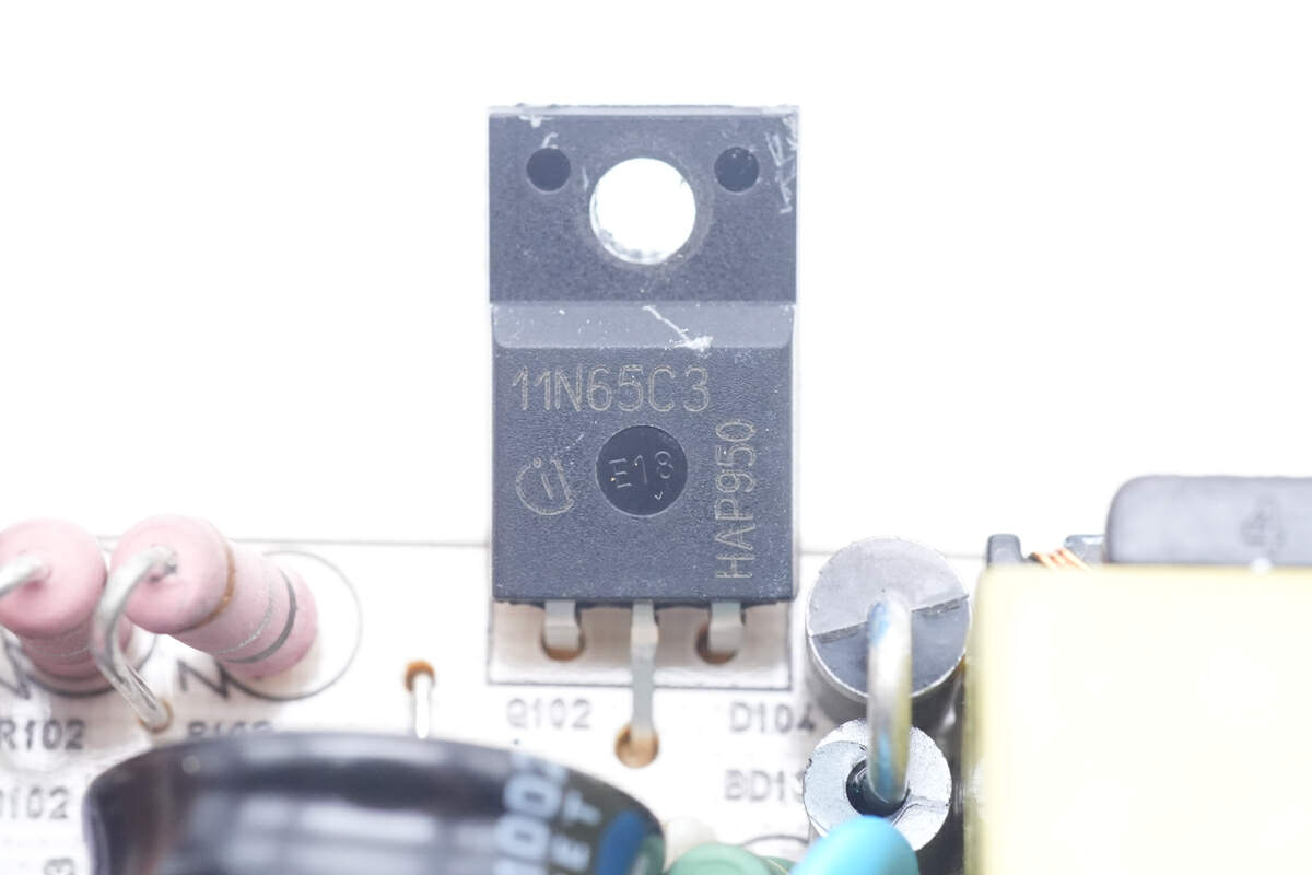
The other primary MOSFET is also from Infineon, but in a different model. It adopts TO220FP package. Model is SPA11N65C3. 650V 380mΩ.
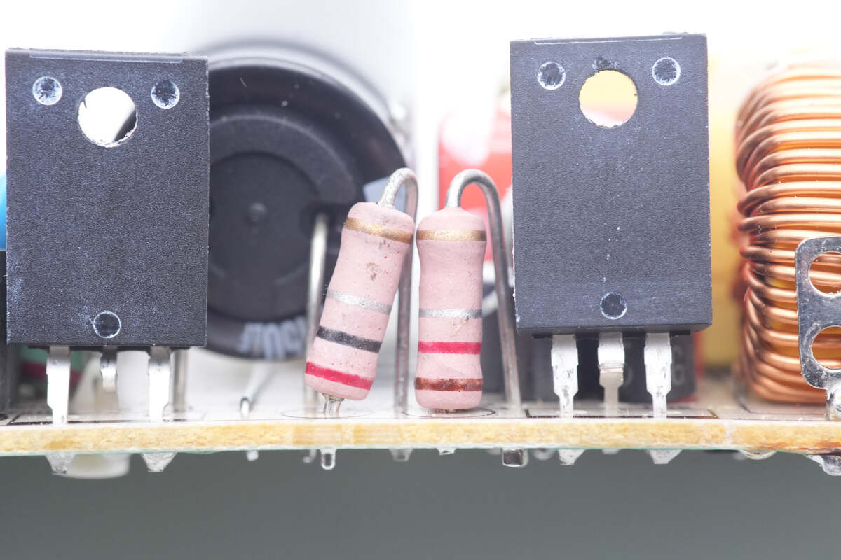
Those two resistors are placed between two MOSFETs, and used to detect the current of MOSFETs.
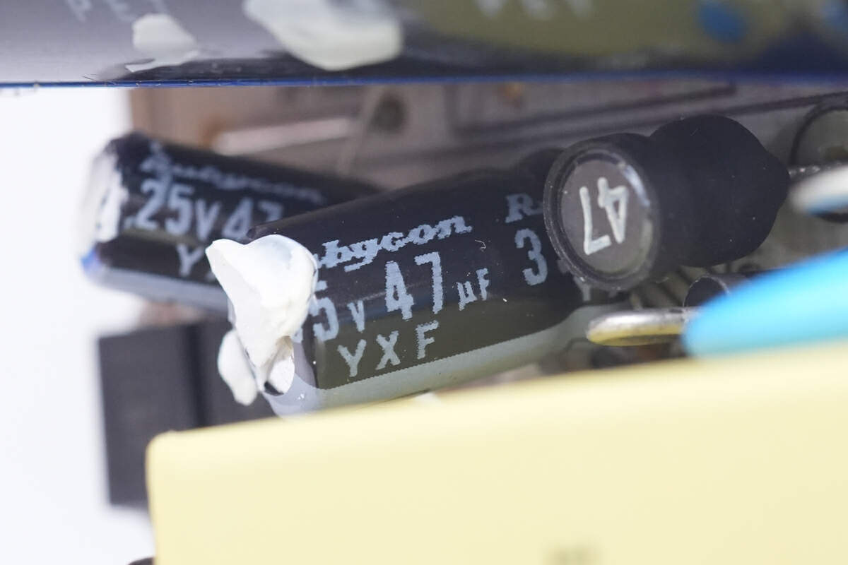
Two capacitors power the master control chip. The larger one is 35V 47μF.
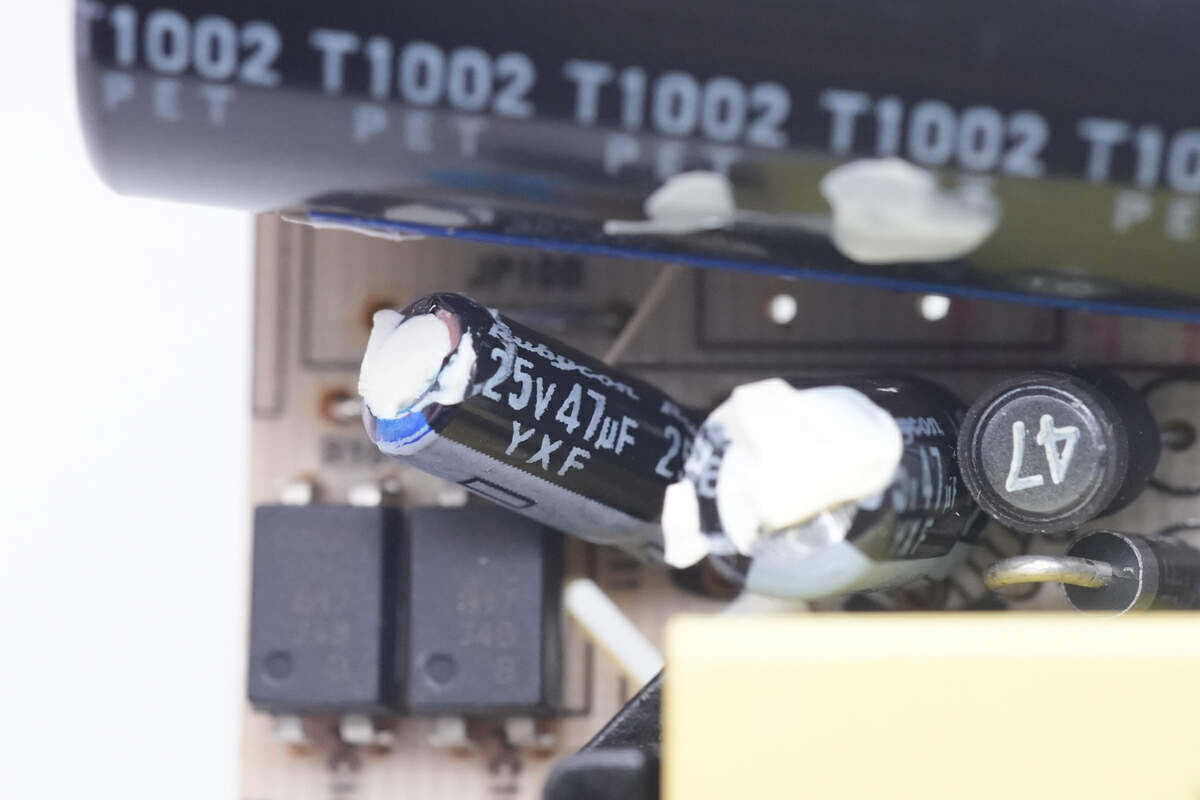
And the smaller one is 25V 47μF.
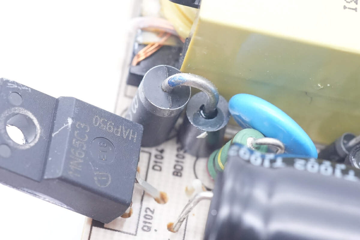
This is the diode for RCD snubber circuit.
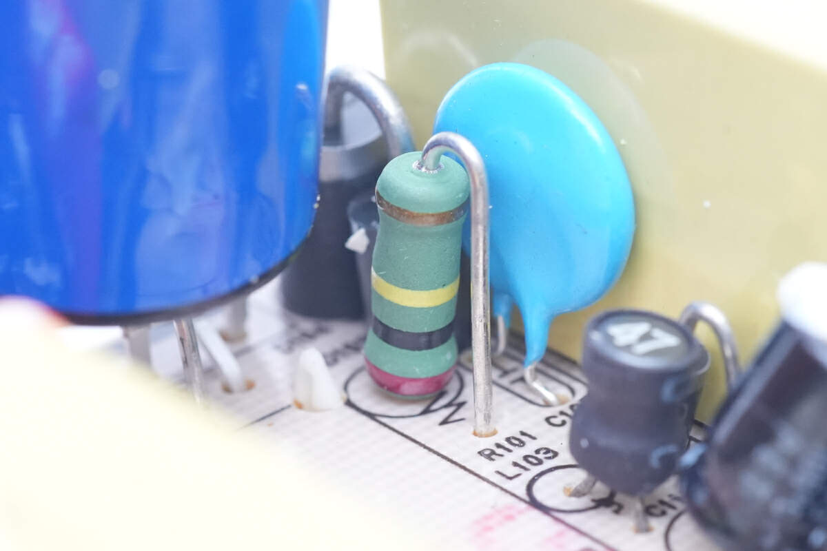
And the resistor for RCD snubber circuit.
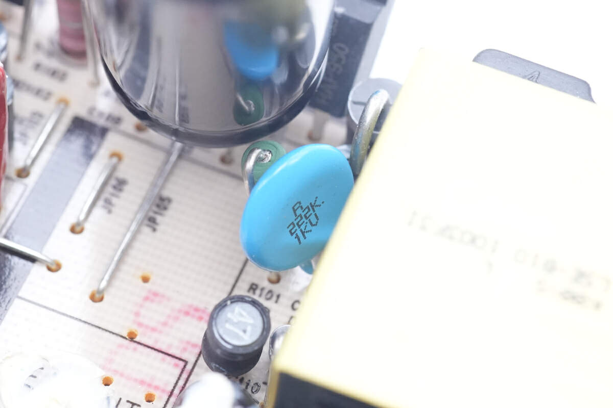
Here is the ceramic capacitor with a withstand voltage of 1KV.
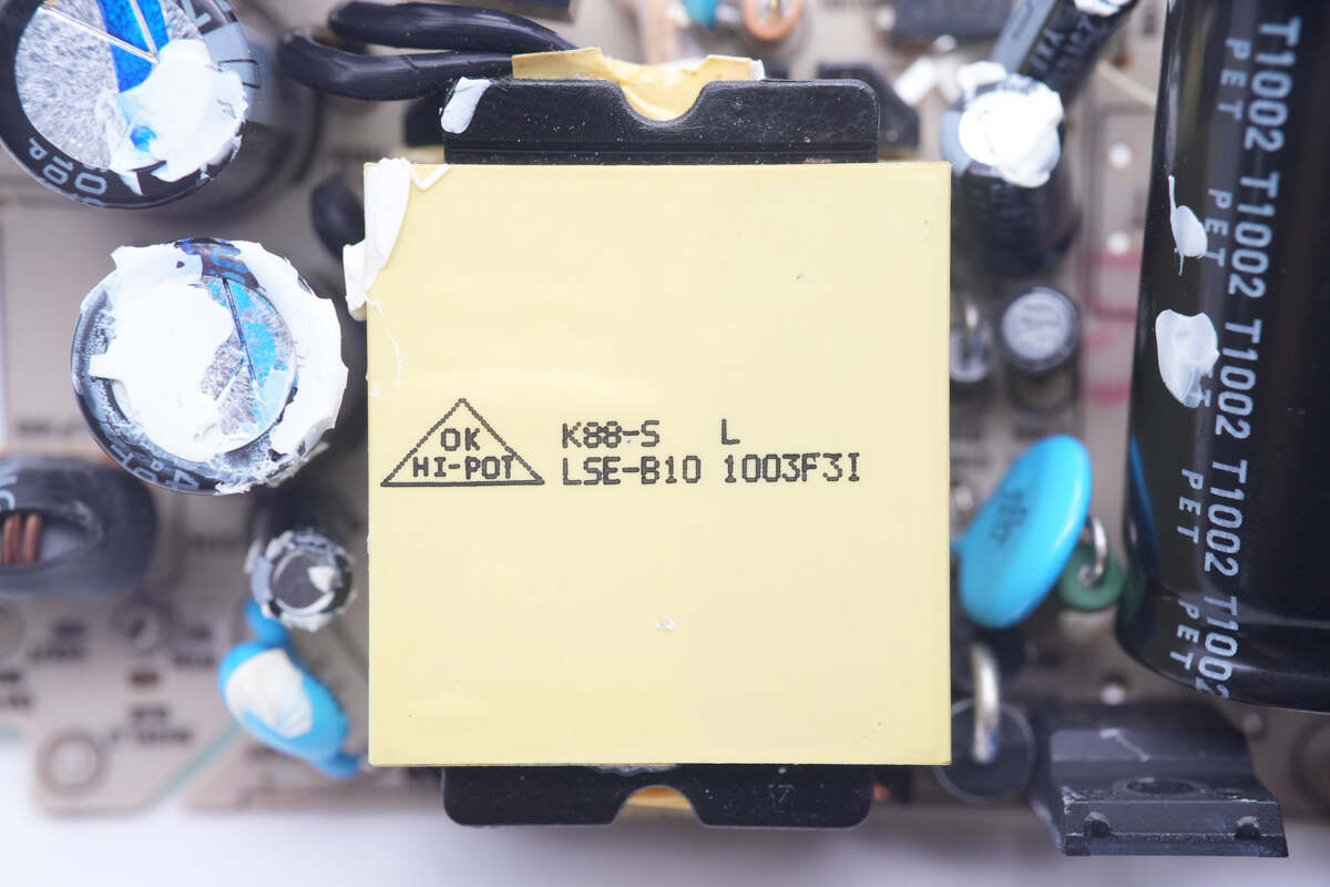
The largest component is the transformer.
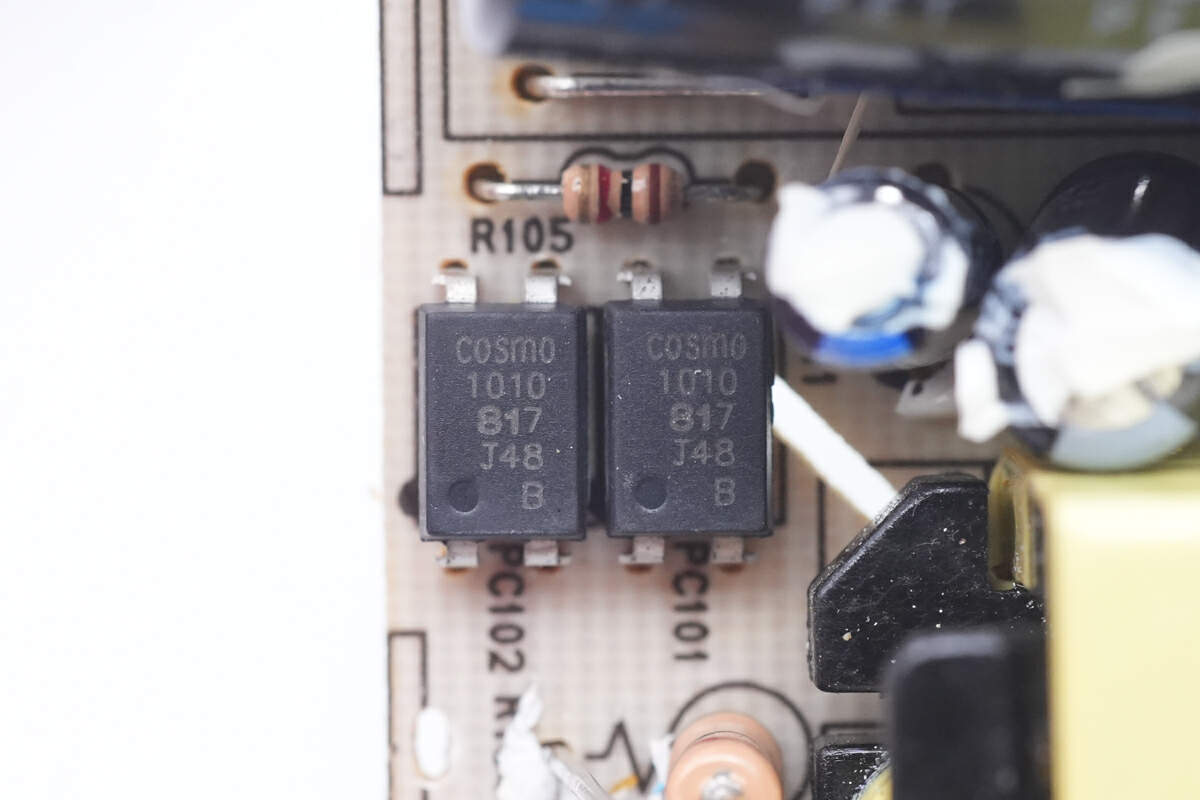
Two 817 optocouplers are next to the transformer, used to regulate the output voltage.
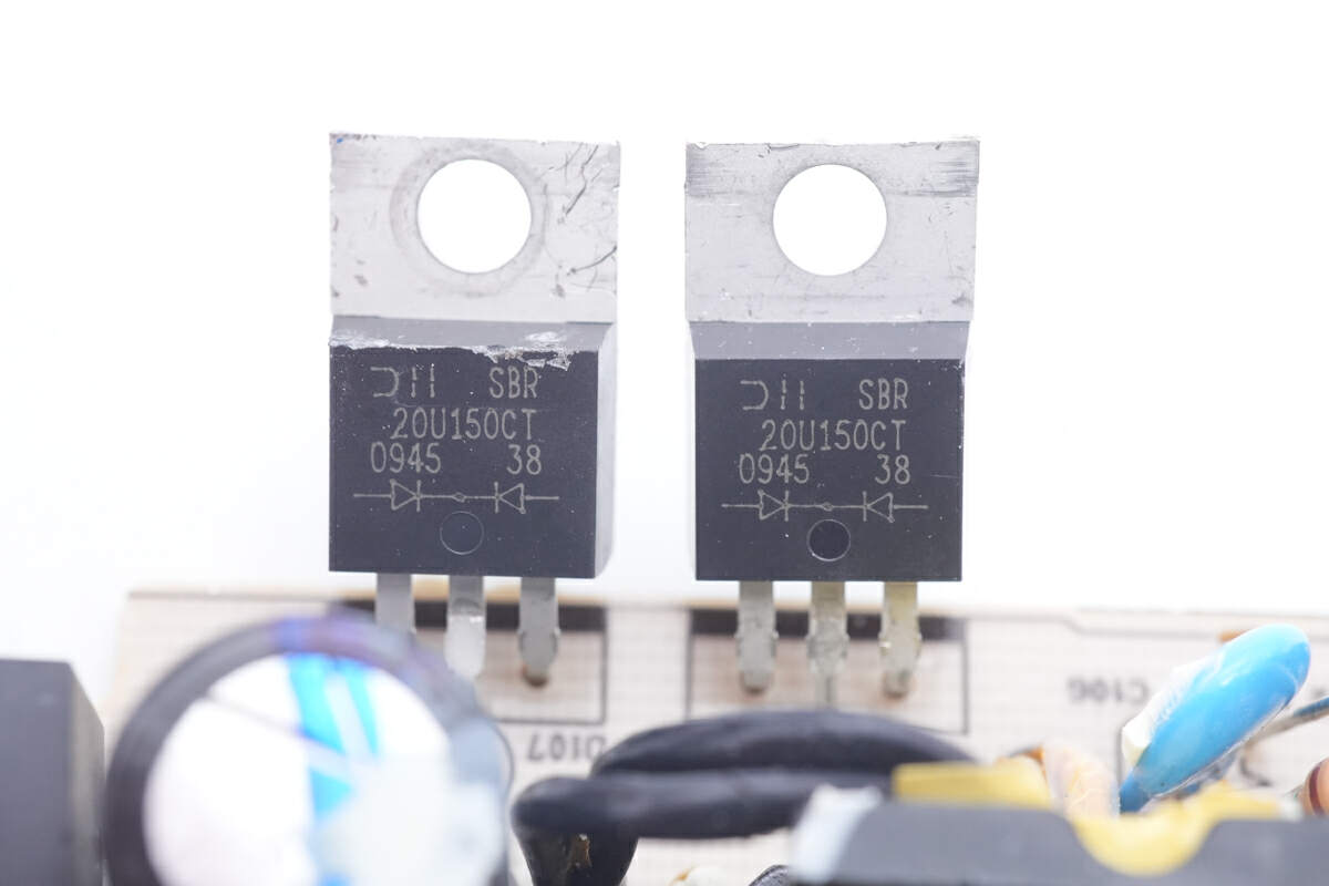
Those three Schottky diodes are from Diodes and adopt TO220 package. They're connected in parallel for rectification. Withstand voltage is 150V and the current is 20A. Model is SBR20U150CT.
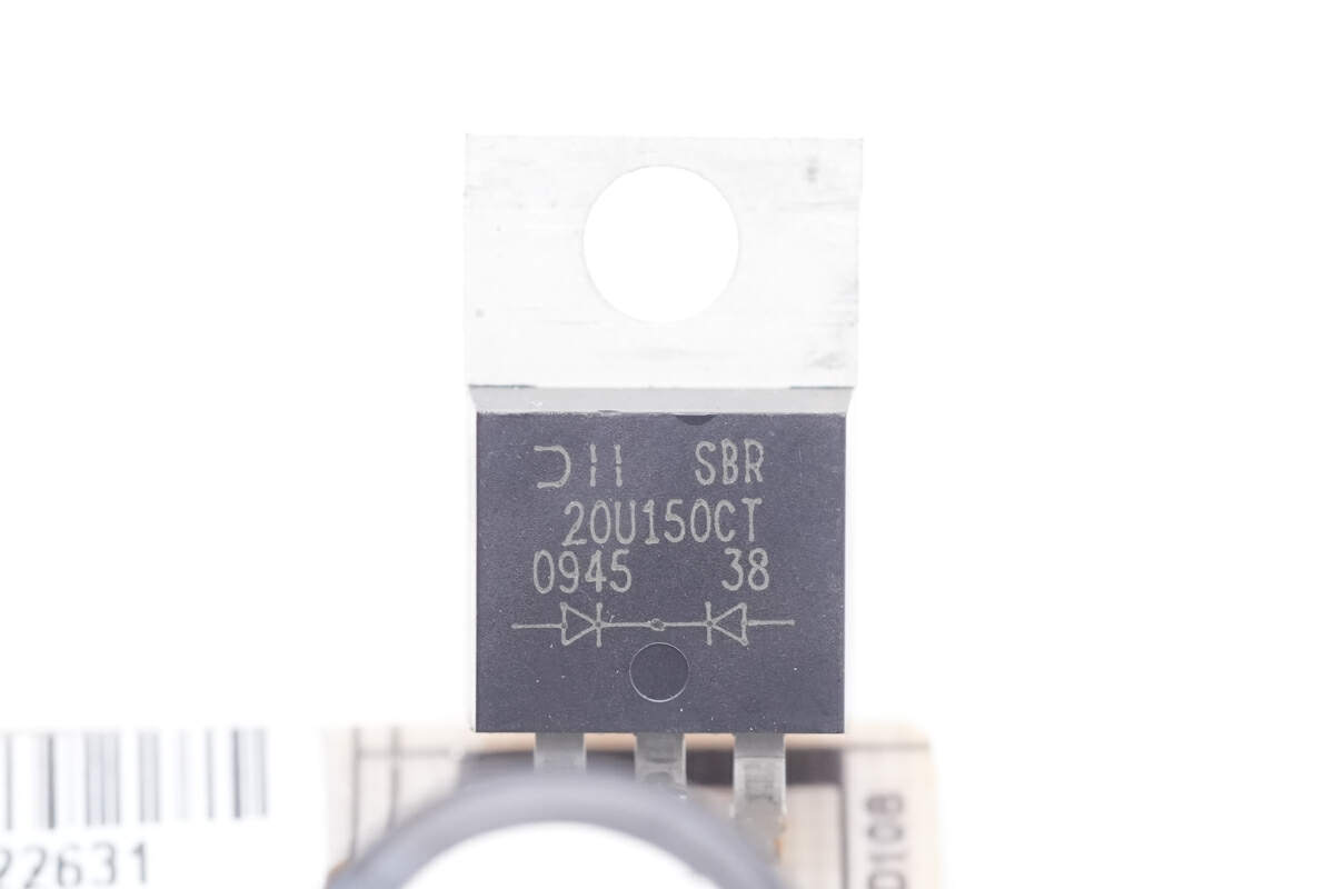
The power adapter uses a total of three Schottky diodes connected in parallel to rectify.
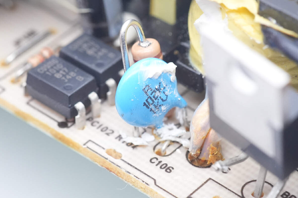
The blue ceramic capacitor is connected in series with a resistor to absorb peak voltages.
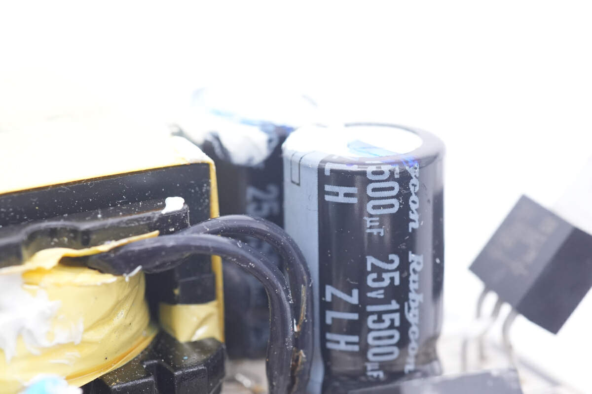
Those two electrolytic capacitors for output filtering are from Rubycon ZLH series. 25V 1500μF for each.
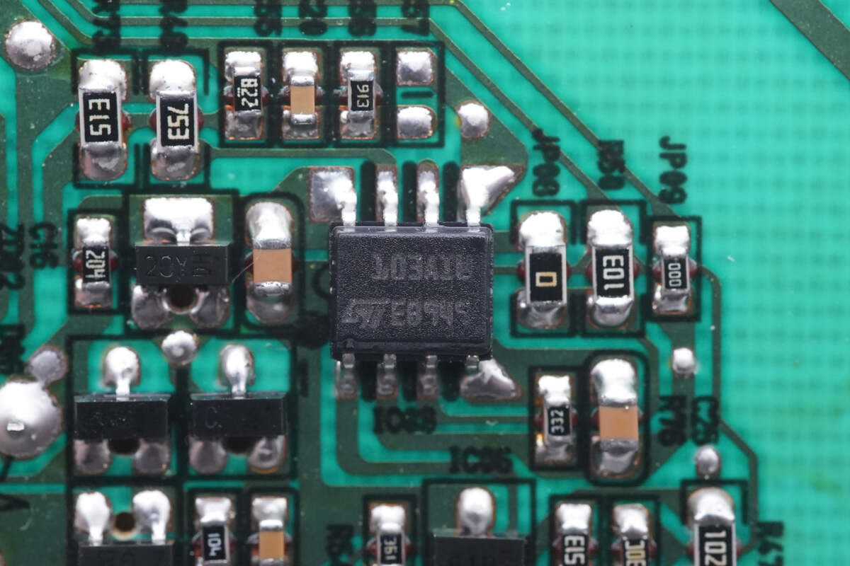
The dual operational amplifier marked with 103AIW is from STMicroelectronics, used for output voltage feedback and constant current control. Model is TSM103WAI.
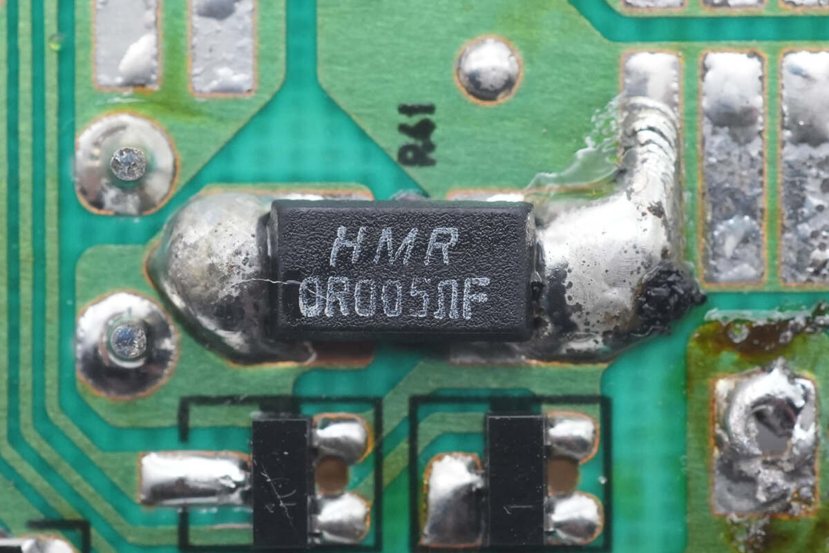
The output current sense resistor is 5mΩ.
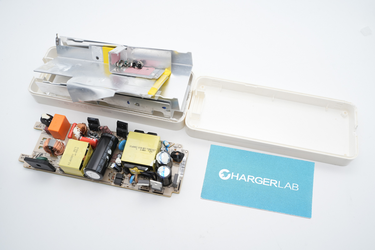
And that's all components of this Apple power adapter released nearly 20 years ago.
Summary of ChargerLAB
The Apple Mac mini 110W power adapter adopts a detachable input power cord design, which makes it easier to replace a faulty or damaged cord without having to replace the entire power adapter unit. This can be more cost-effective and eco-friendly in the long run. And in terms of appearance, It's much like the big and heavy power adapters we've seen on some Windows gaming laptops, but now, the power supply has been integrated into the Mac mini.
After taking it apart, we found that the internal heat dissipation and protection measures are similar to the current Apple power adapter, which makes this charger high quality, but the internal module design is not very compact, and the topology is relatively outdated.
Related Articles:
1. Teardown of Apple 143W Power Adapter (For all-new 24” iMac)
2. Latest Teardown of Brand New Apple 140W USB-C GaN Charger
3. Back to 2006 | Teardown of Old Apple 110W Power Adapter (Video)

