Introduction
Tesla is a well-known electric car company that launched a wireless charger with its cable in 2021. Recently, Tesla launched a wireless portable charger with a sense of design. The wireless portable charger has a USB-C cable and a USB-C port and features a flip-top design that allows it to wirelessly charge two devices simultaneously. It even supports wireless input.
ChargerLAB has tested it earlier, and the details can be seen in the charging test. Next, let's take it apart to see its internal components and structure.
Product Appearance
"Tesla Wireless Portable Charger" is printed on the top of the black packaging box.
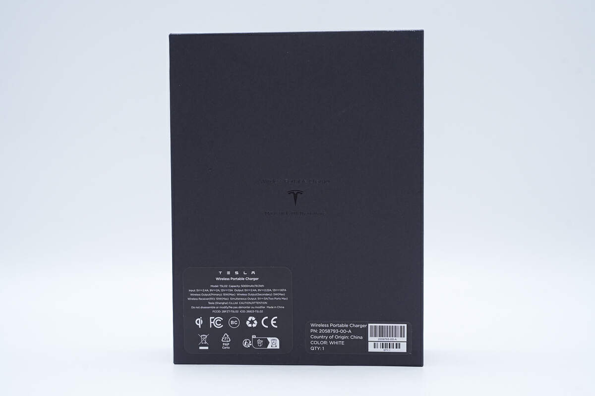
The specs info is printed on the back of the box, we will talk about it later.
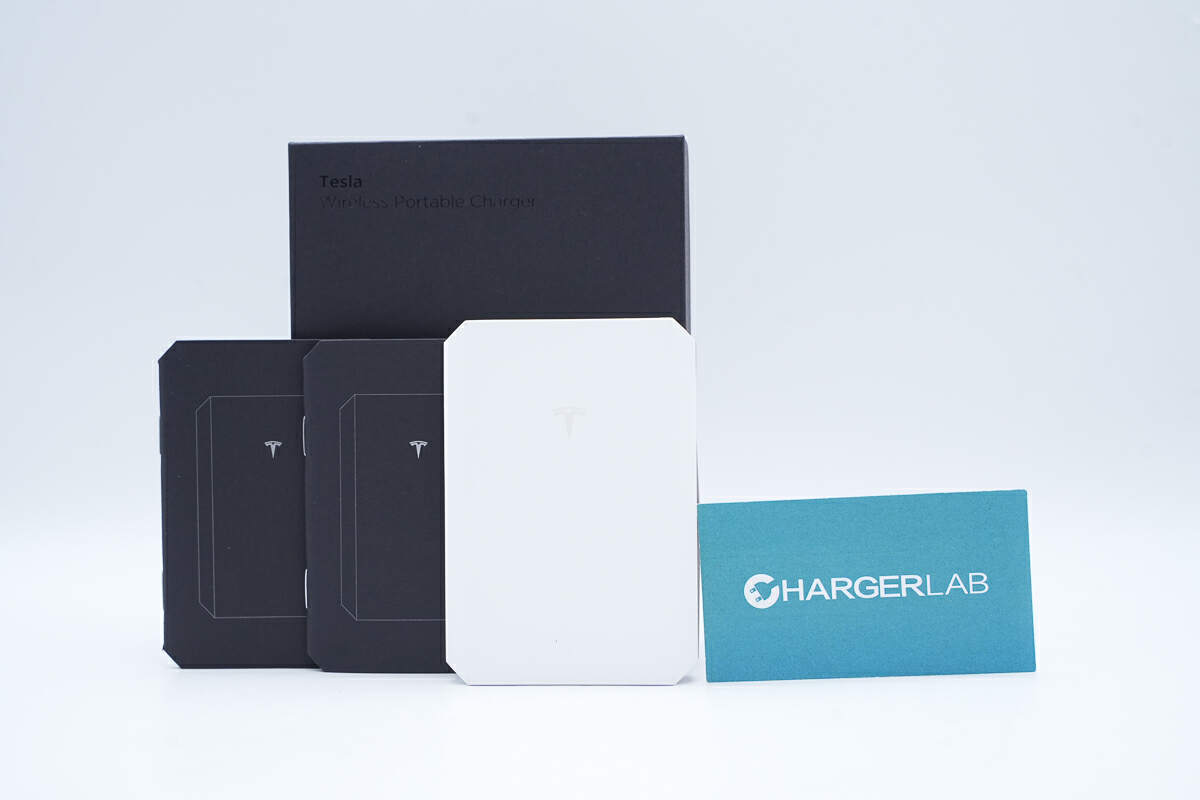
The box contains the charger and some documents.
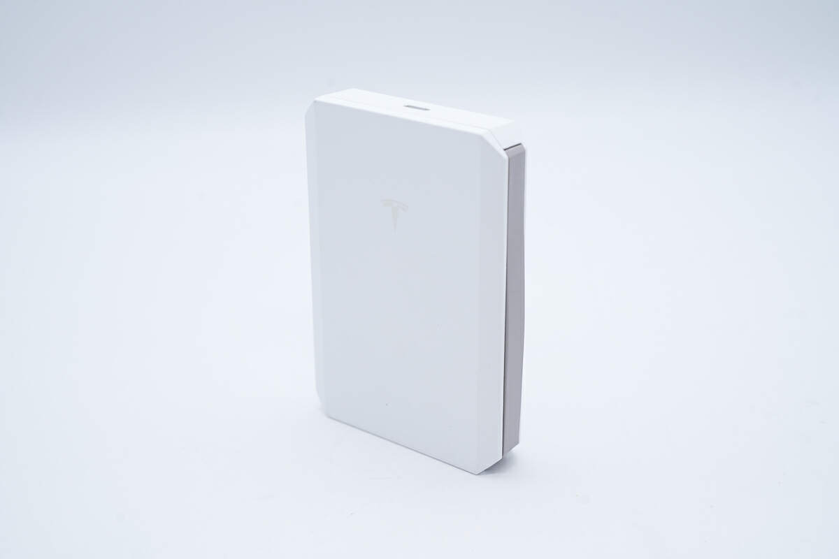
The shell is made of plastic and covered with metallic paint, with sharp edges and corners.
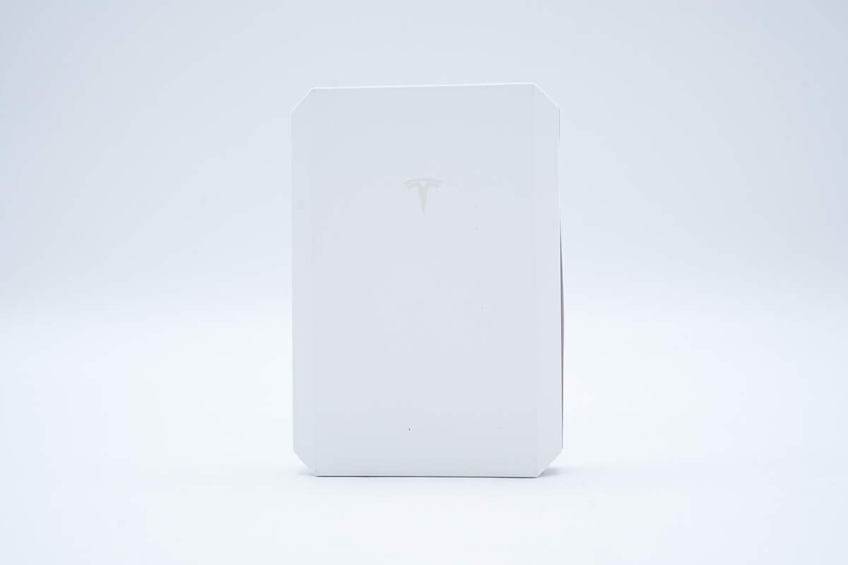
The front, which is the wireless charging panel, is engraved with the Tesla logo.
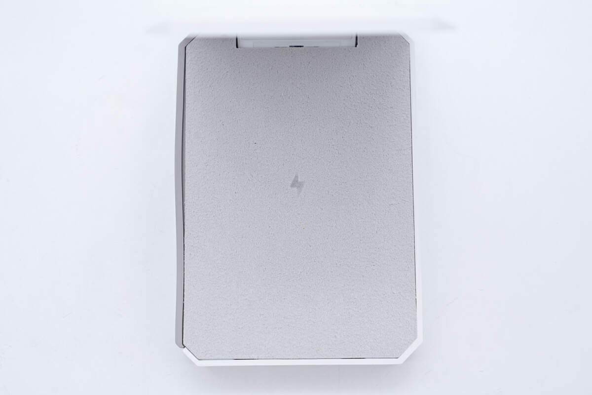
Open the primary wireless charging panel, and you will see a wireless charging panel on the inside, which is covered with Alcantara suede to prevent the device from being scratched and enhance friction.
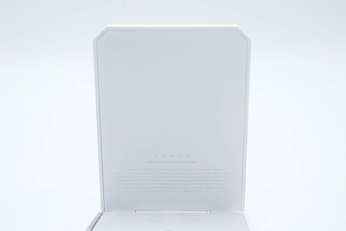
The specs info is printed inside.
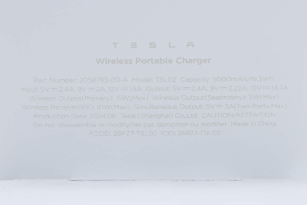
Model is TSL02. The capacity is 5000mAh, and the energy is 19.3Wh. It can support input of 5V2.4A, 9V2A, and 12V1.5A. The maximum output is 20W. The maximum wireless output (primary) is 15W. The maximum wireless output (secondary) is 5W. The maximum power of the wireless receiver is 10W.
The back design is extremely simple.
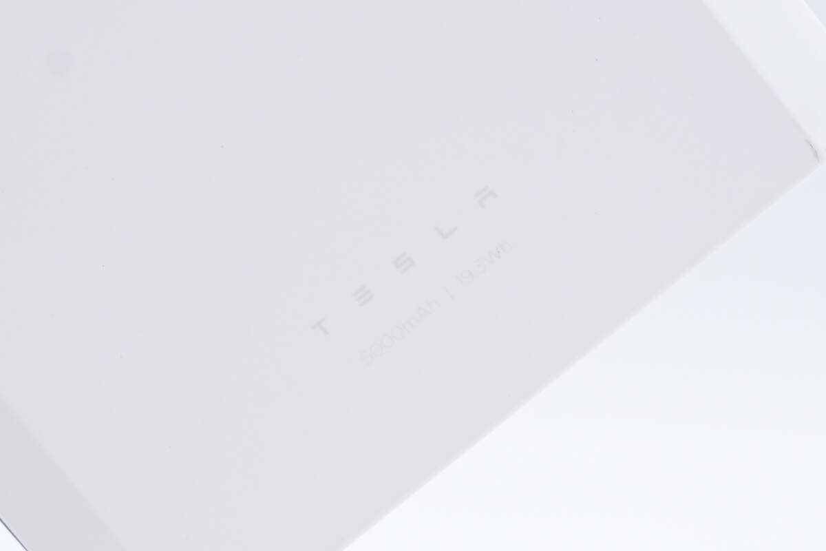
The capacity is 5000mAh, and the energy is 19.3Wh.
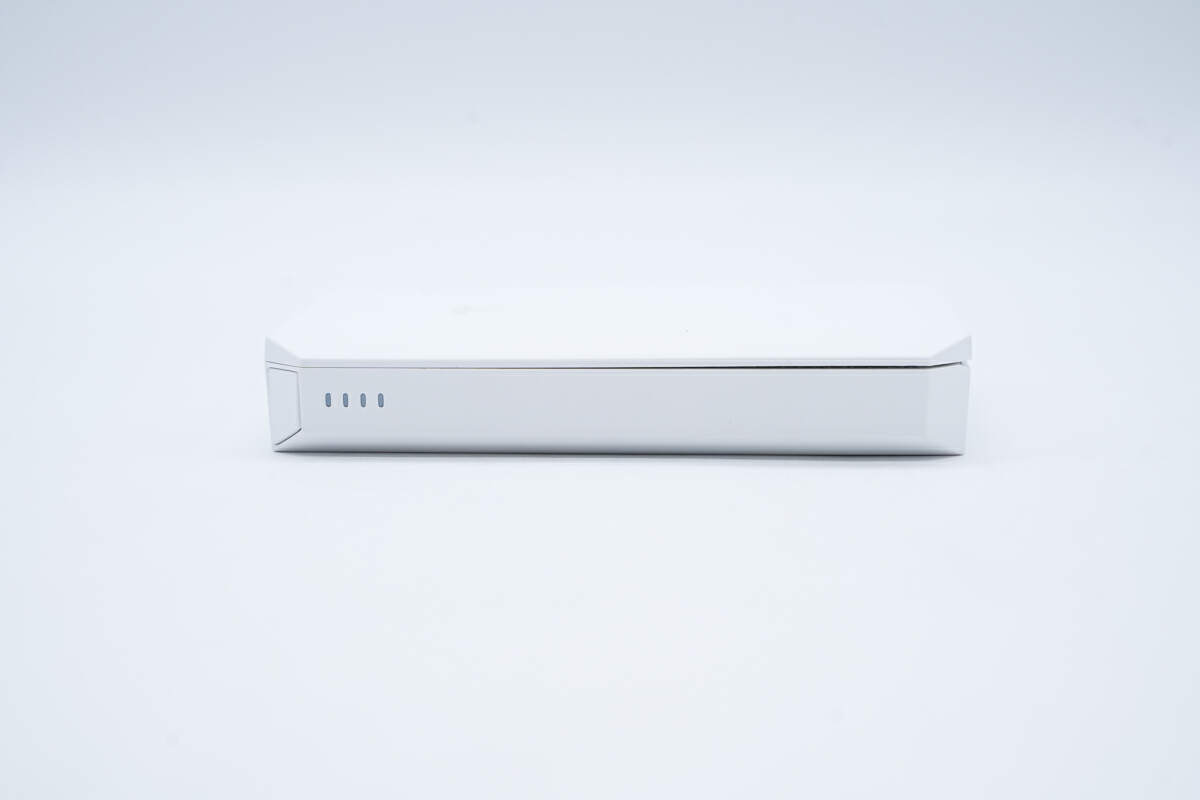
There are four LED indicators on the side.
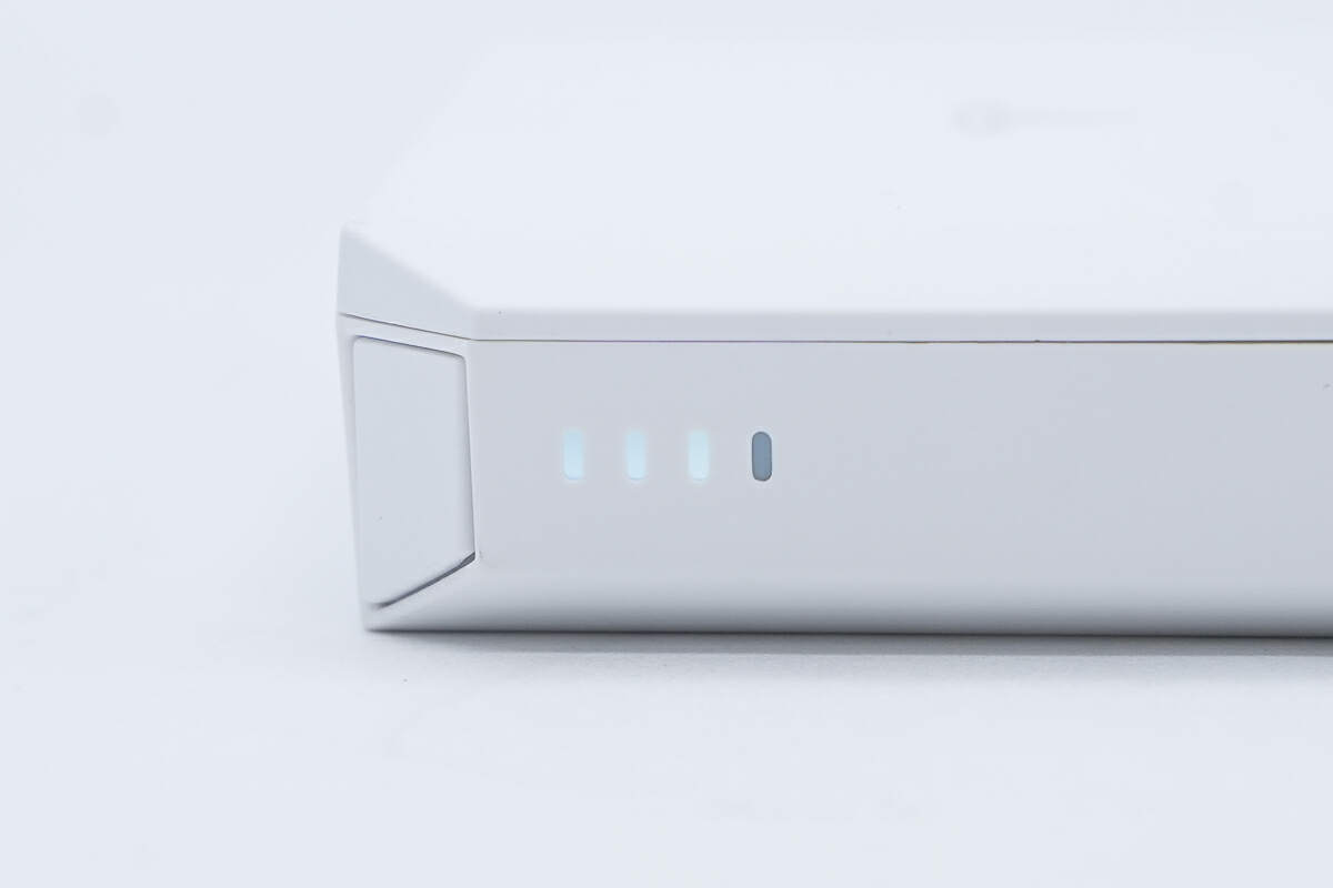
Each indicator represents 25% of the battery capacity.
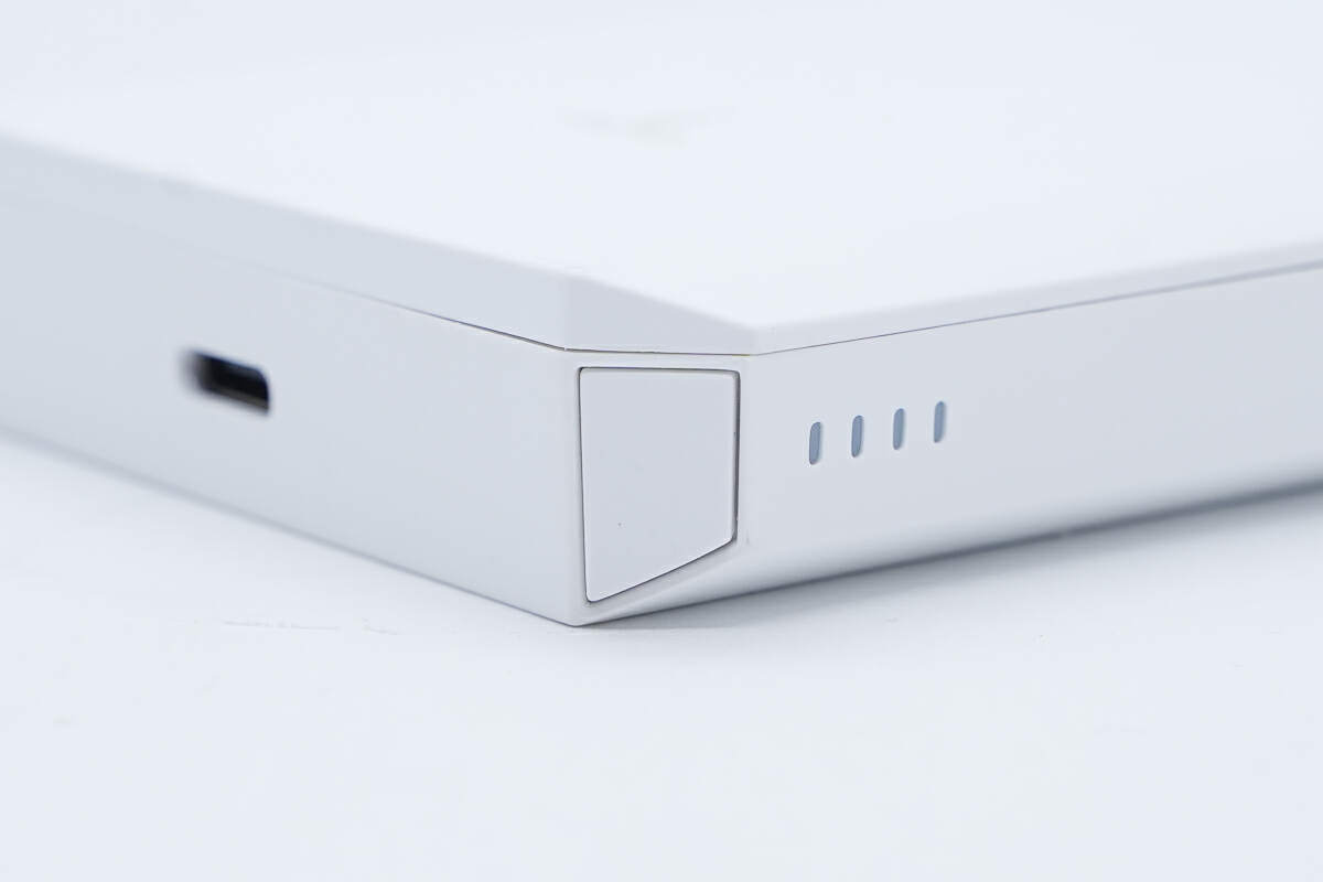
Above the power indicators is the power button.
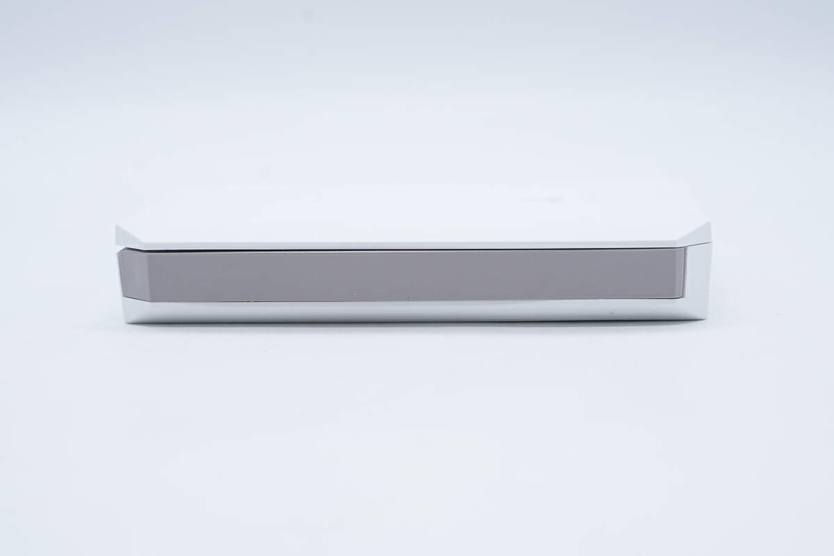
The integrated USB-C cable is on the other side.
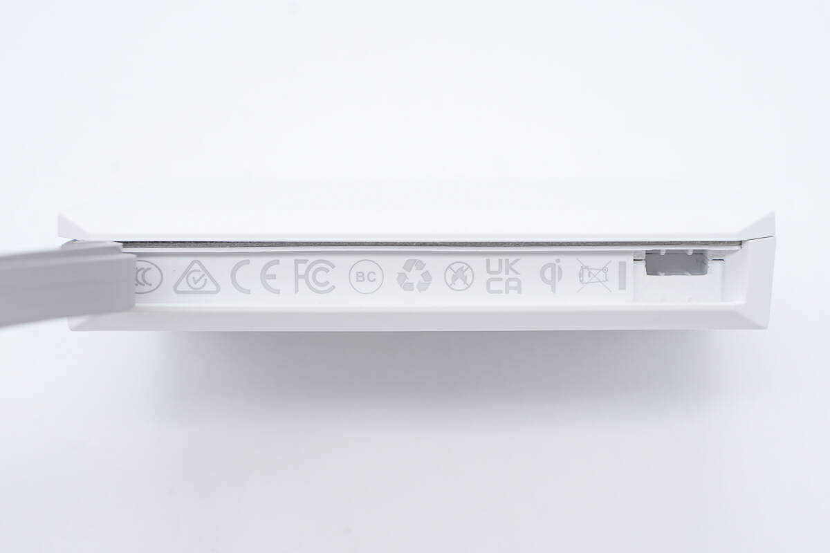
The certifications it has passed are printed on the inside.
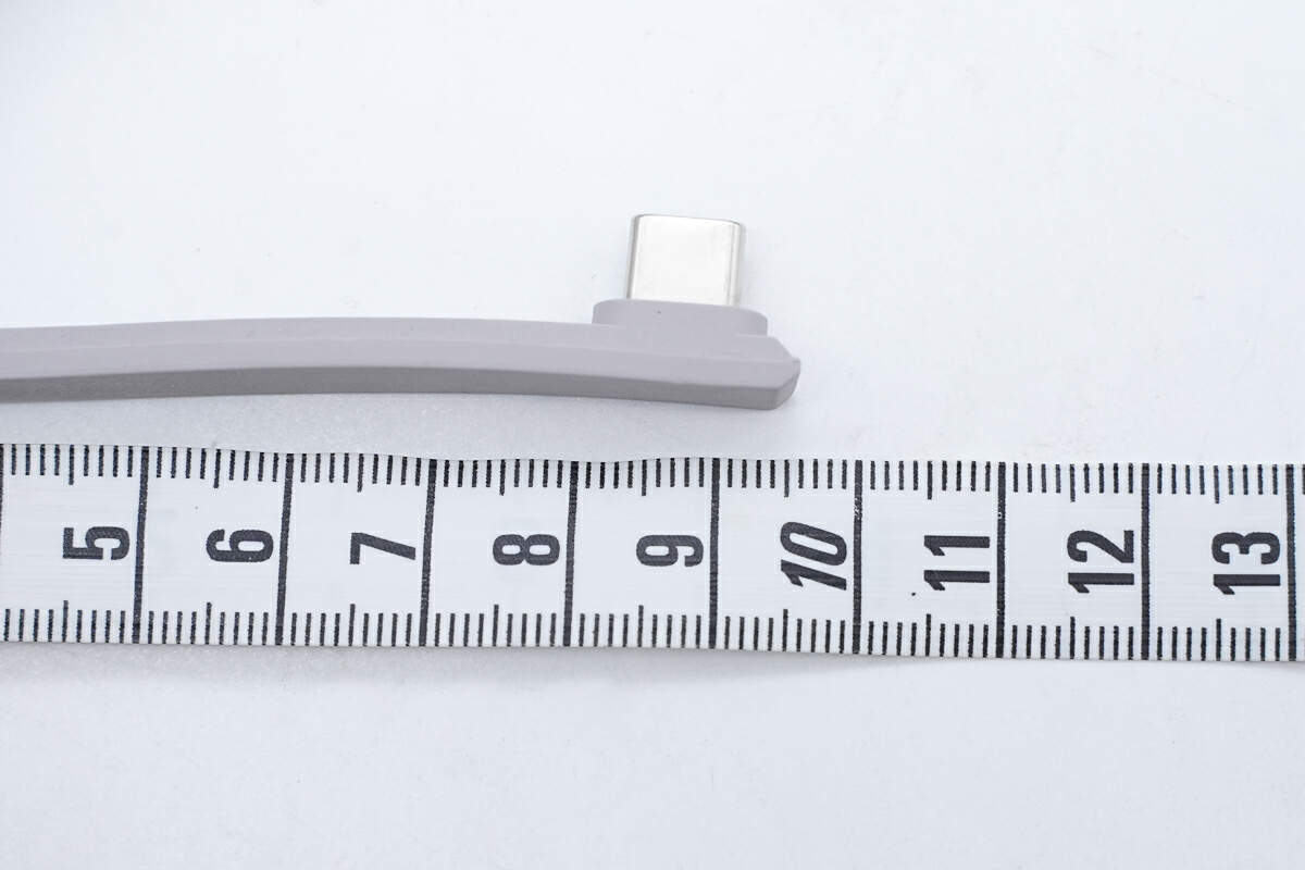
The length of the integrated cable is about 10 cm (3.94 inches).
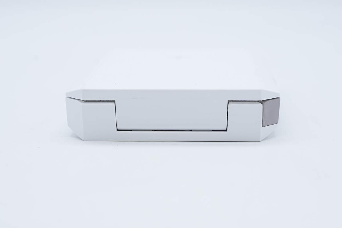
The hinge is at the bottom.
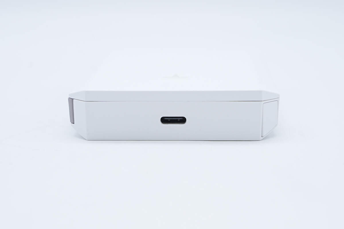
There is a USB-C port on the top, and the plastic sheet is black.
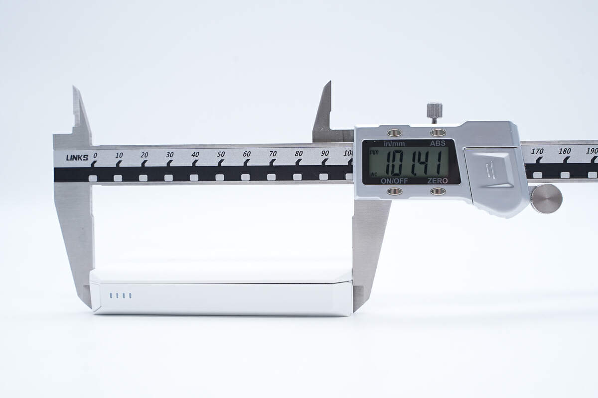
The length is about 101.4 mm (3.99 inches).
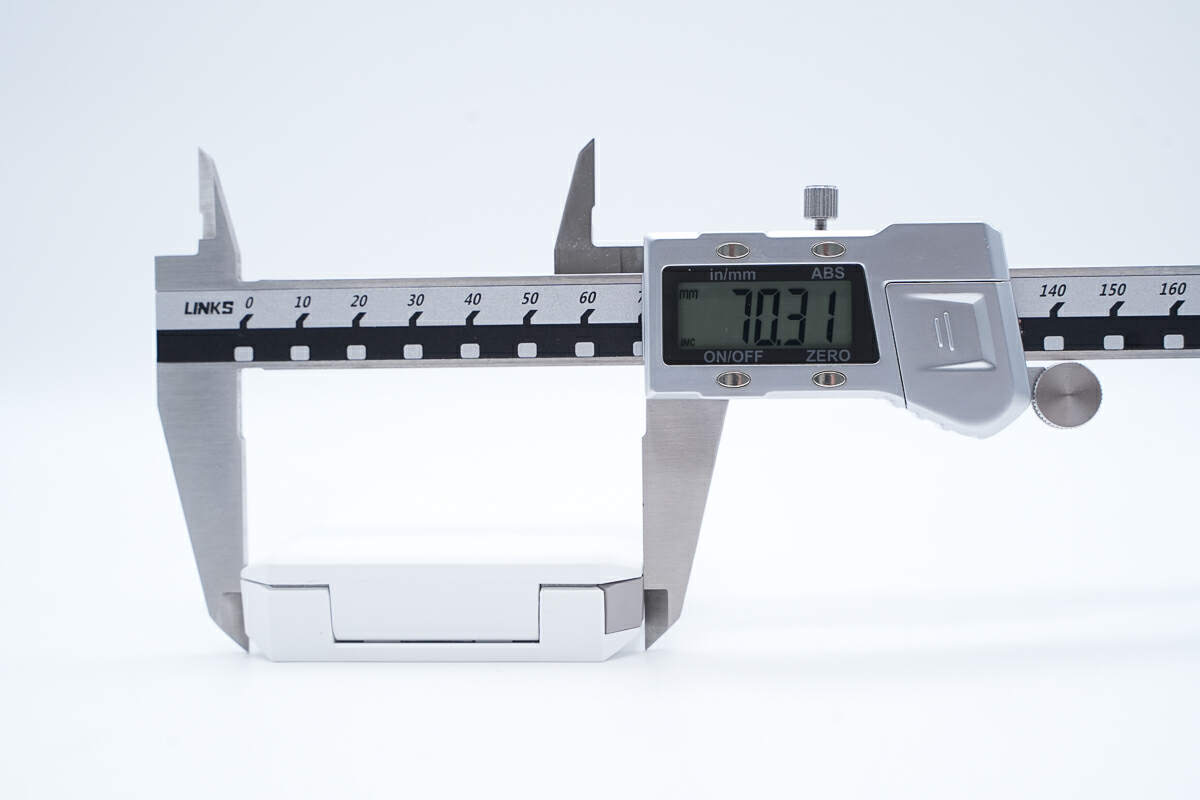
The width is about 70.3 mm (2.77 inches).
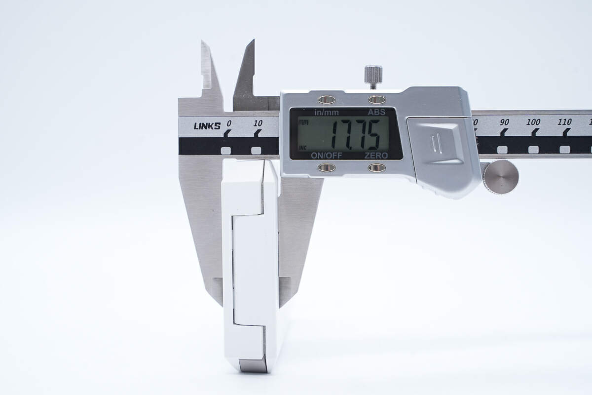
The thickness is about 17.8 mm (0.7 inches).
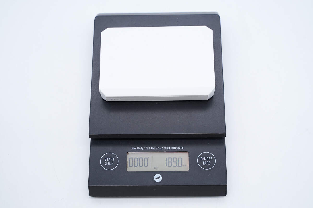
And the weight is about 189 g (6.67 oz).
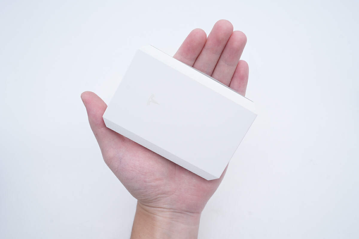
That's how big it is in the hand.
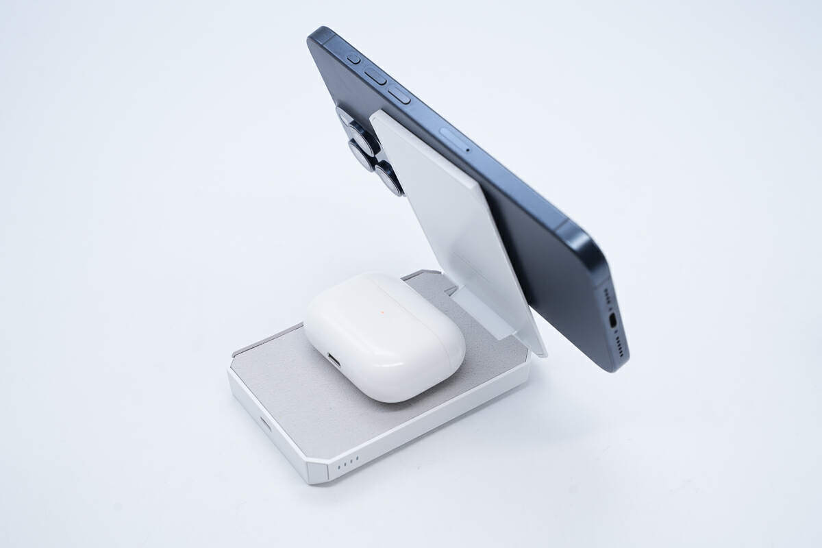
It can wirelessly charge two devices at the same time.
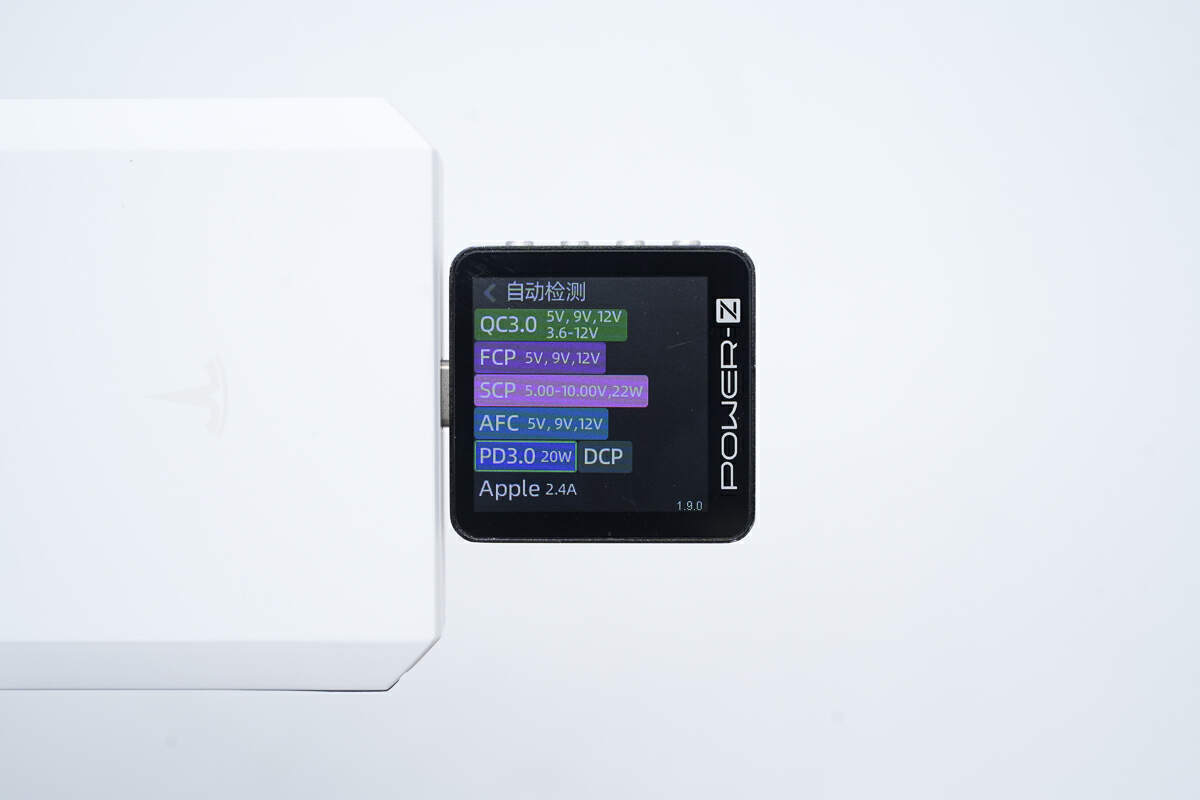
ChargerLAB POWER-Z KM003C shows the USB-C port can support QC3.0, FCP, SCP, AFC, PD3.0, DCP, and Apple 2.4A charging protocols.
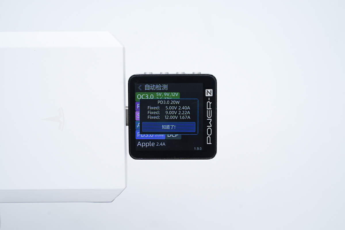
And it has three fixed PDOs of 5V/2.4A, 9V/2.22A, and 12V/1.67A.
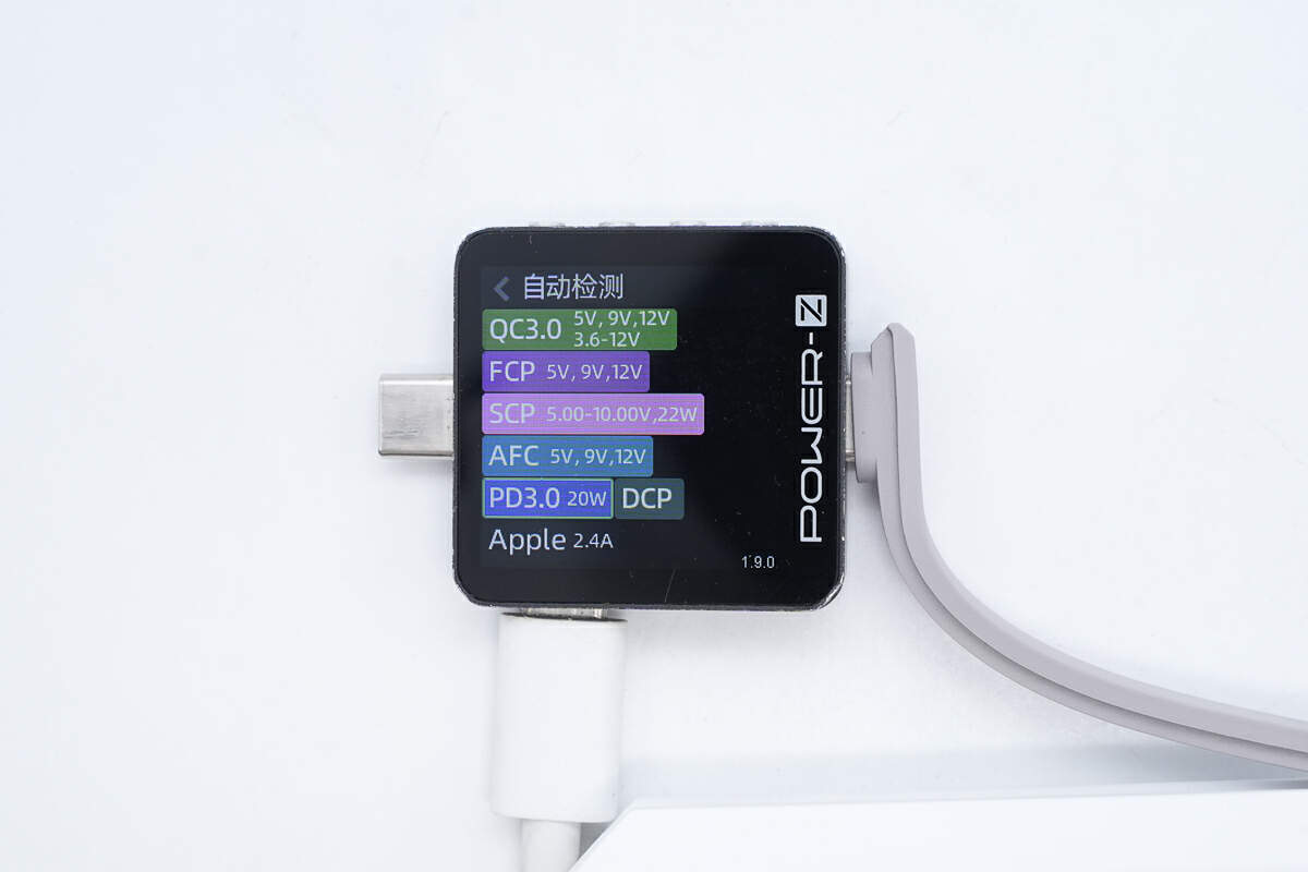
ChargerLAB POWER-Z KM003C shows the USB-C cable can support QC3.0, FCP, SCP, AFC, PD3.0, DCP, and Apple 2.4A charging protocols.
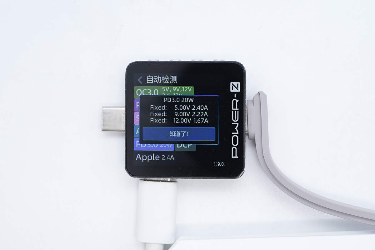
And it has three fixed PDOs of 5V/2.4A, 9V/2.22A, and 12V/1.67A.
Teardown
Next, let's take it apart to see its internal components and structure.
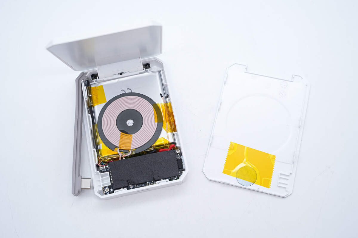
First, pry off the secondly wireless charging panel along the gap, which has a wireless charging coil inside.
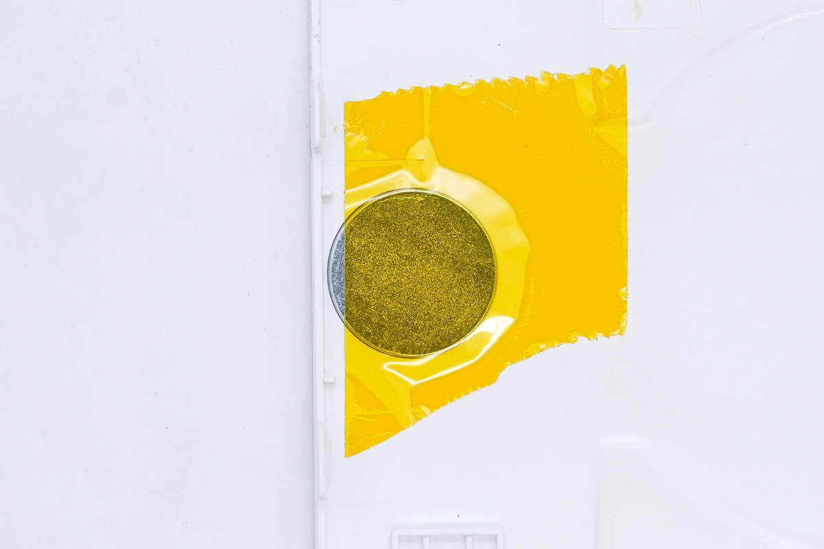
There is a magnet inside the cover to absorb the wireless charging coil on the top cover.
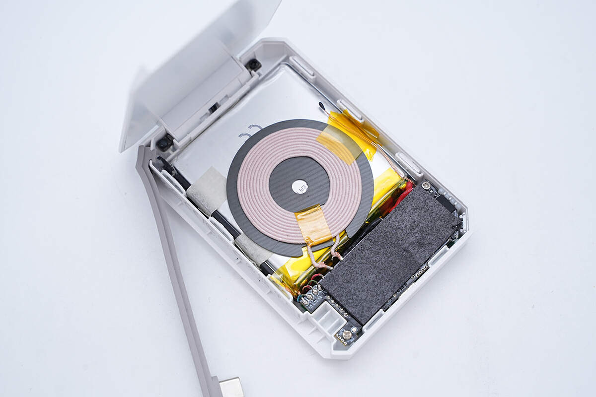
The wireless charging coil is attached to the battery.
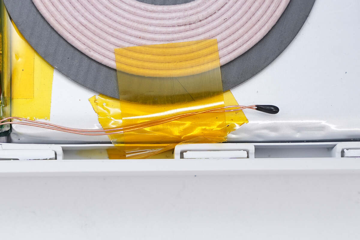
The thermistor on the battery is used to detect temperature.
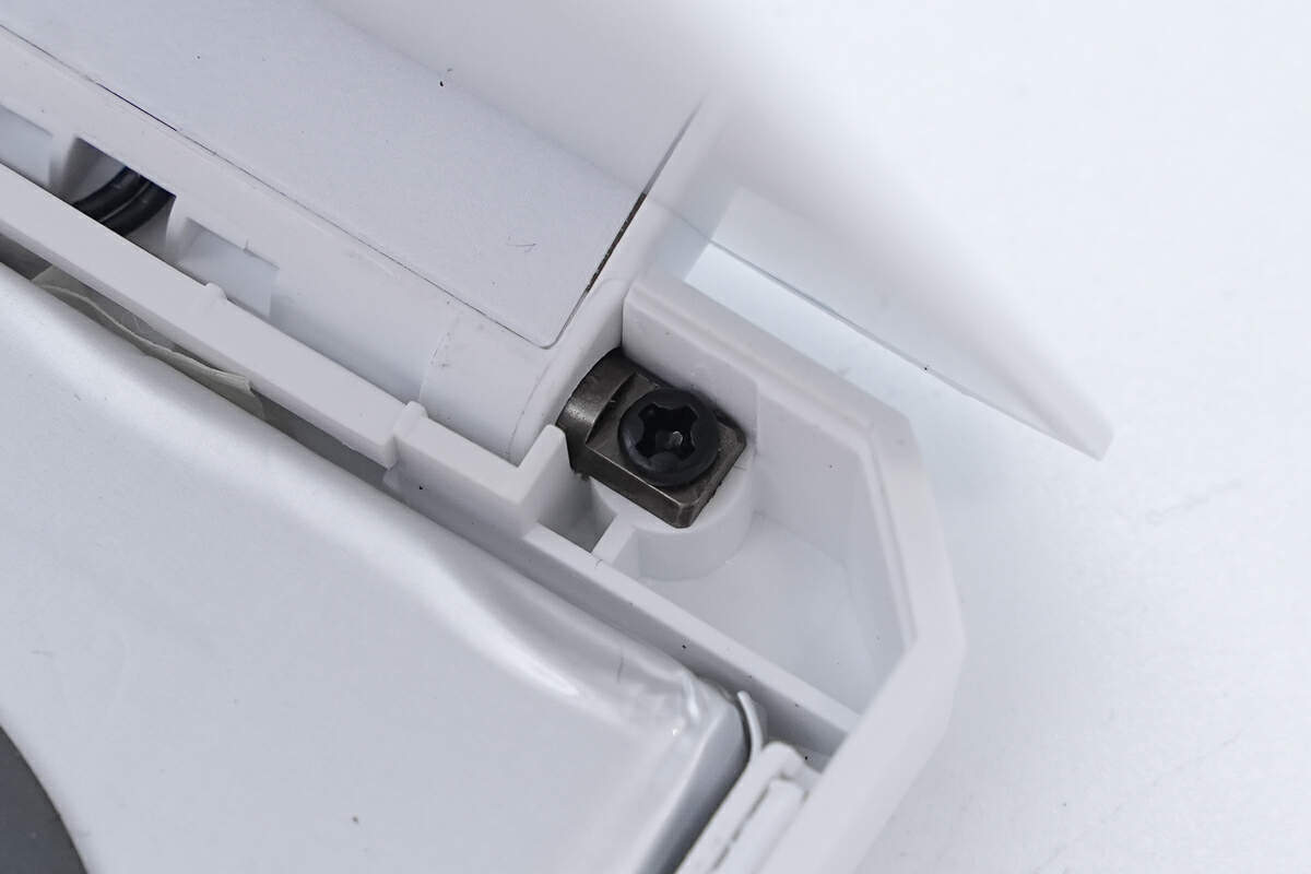
顶盖采用金属转轴固定。
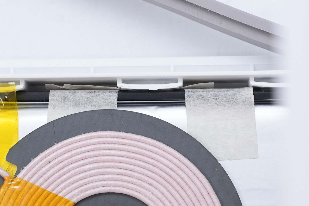
The wires of the wireless charging coil are fixed with tape.
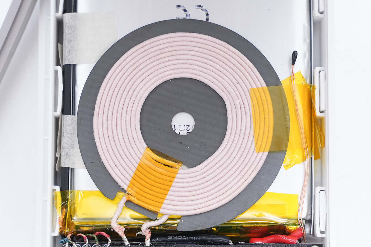
The wireless charging coil is wound with yarn-wrapped wire.
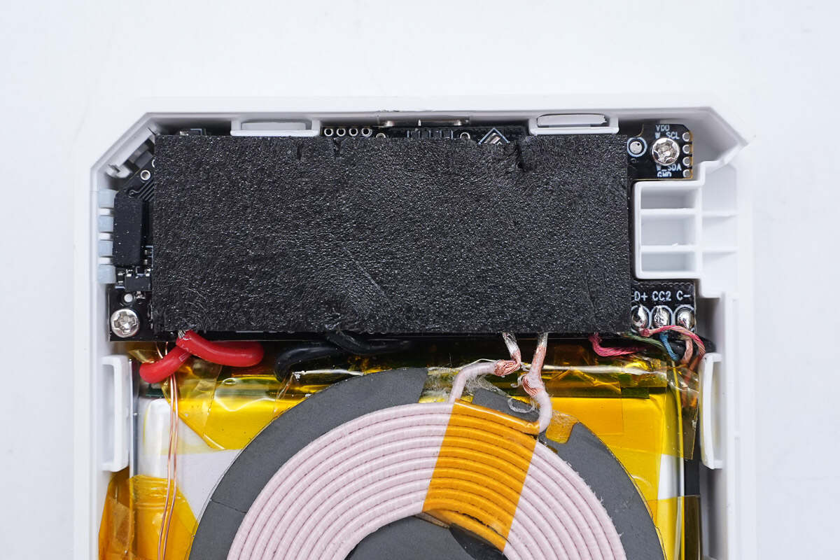
There is foam on the PCBA module for cushioning.
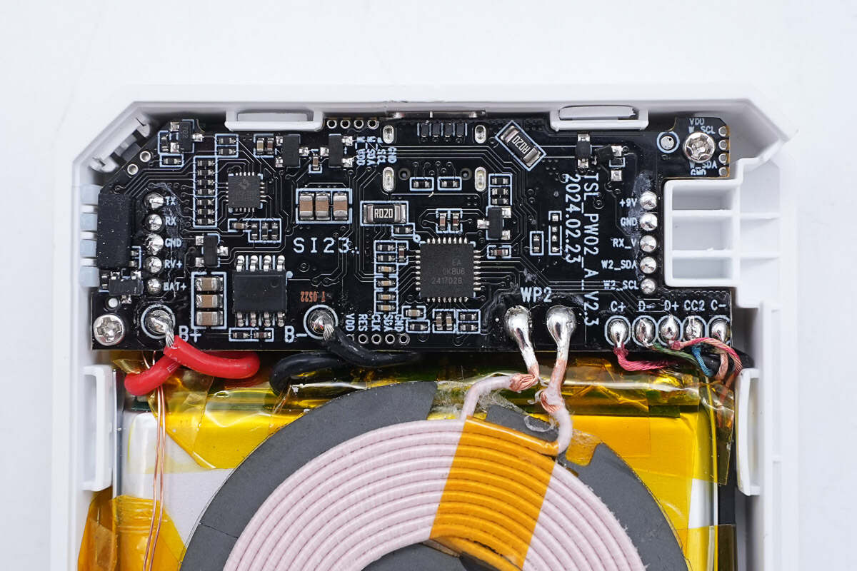
Tear off the foam, here is the PCBA module.
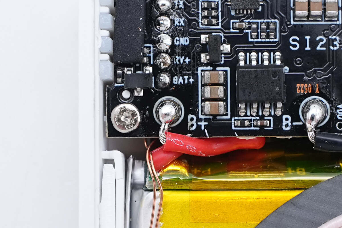
The battery pack is soldered to the PCBA module via wires.
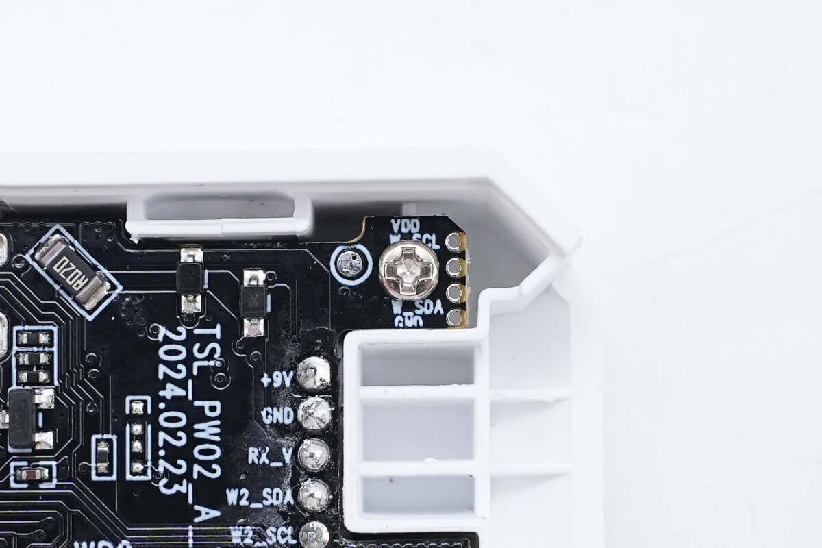
This is the screw used to fix the PCBA module.
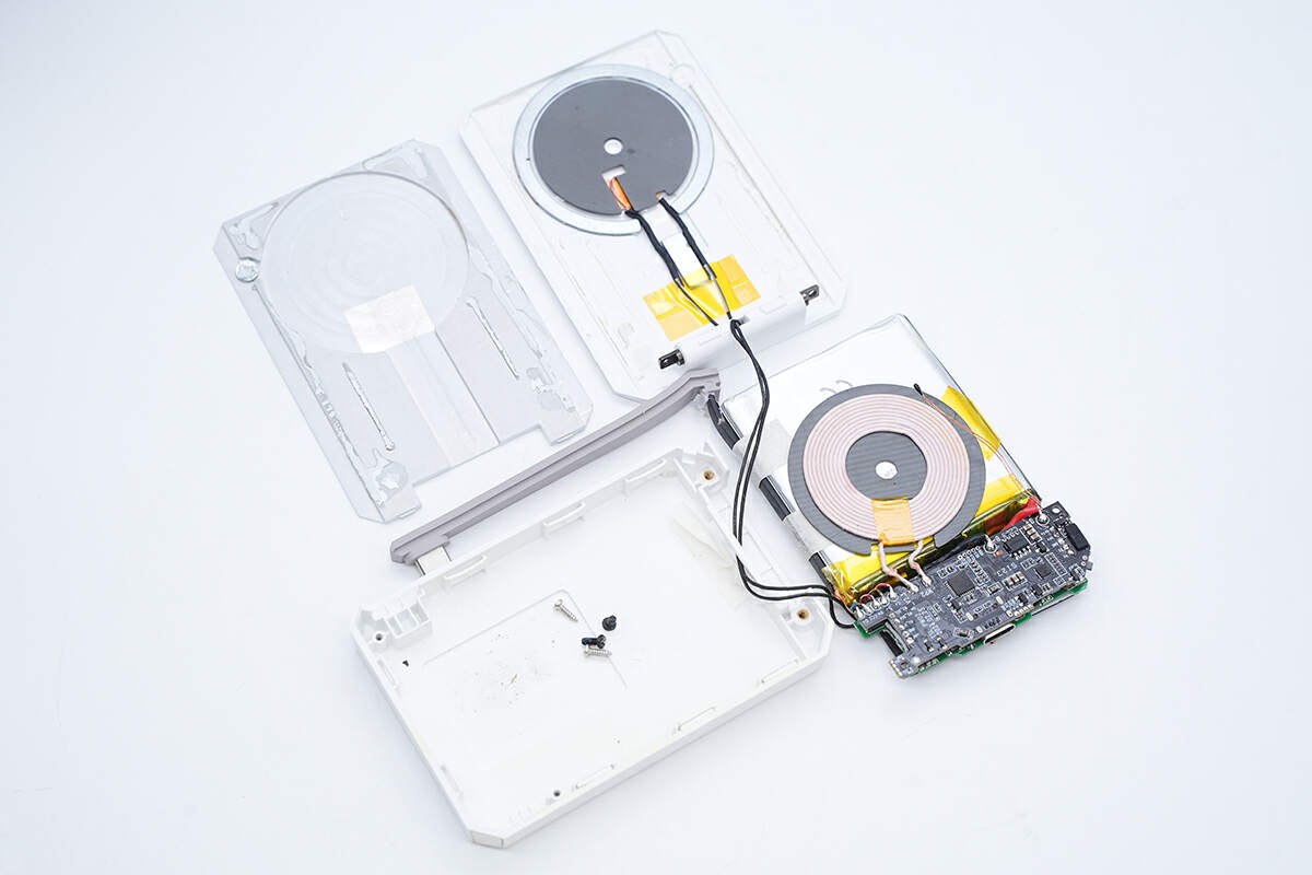
Remove the PCBA module, battery pack, and coil from the shell.
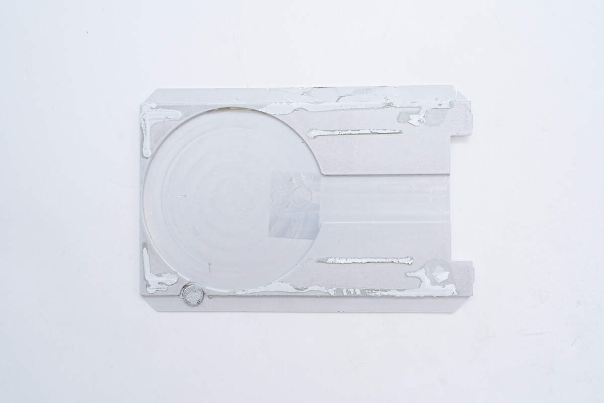
The back of the cover is fixed by glue.
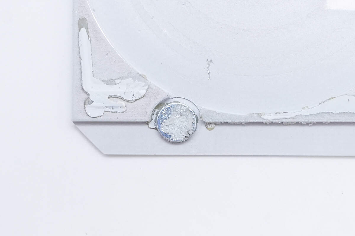
There is also a magnet here that holds the wireless charging coil inside the flap.
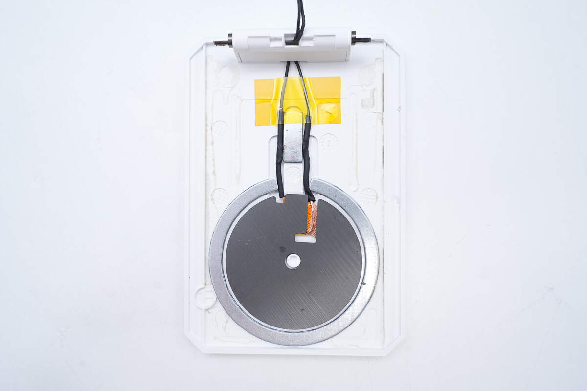
This is the wireless charging coil inside the flip cover.
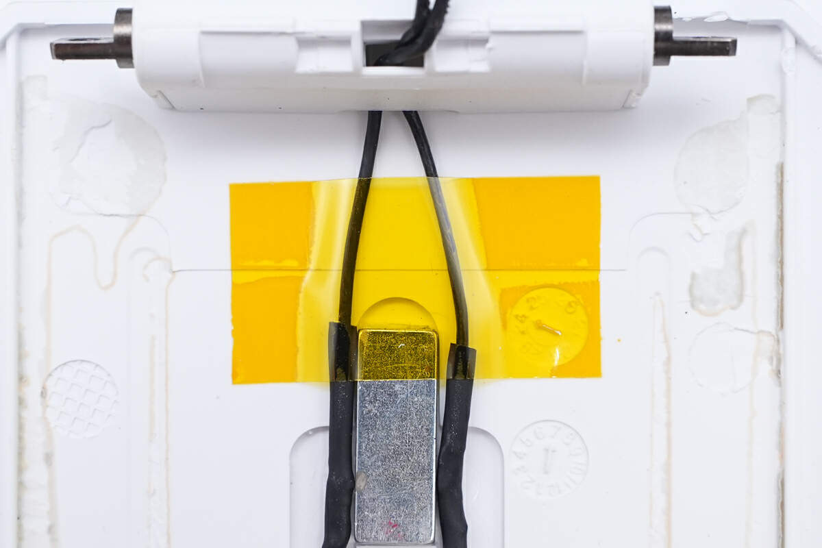
The wires are insulated by heat-shrinkable tubing and secured with high-temperature tape.
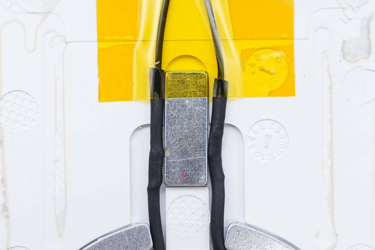
This is a rectangular magnet used to hold phones.
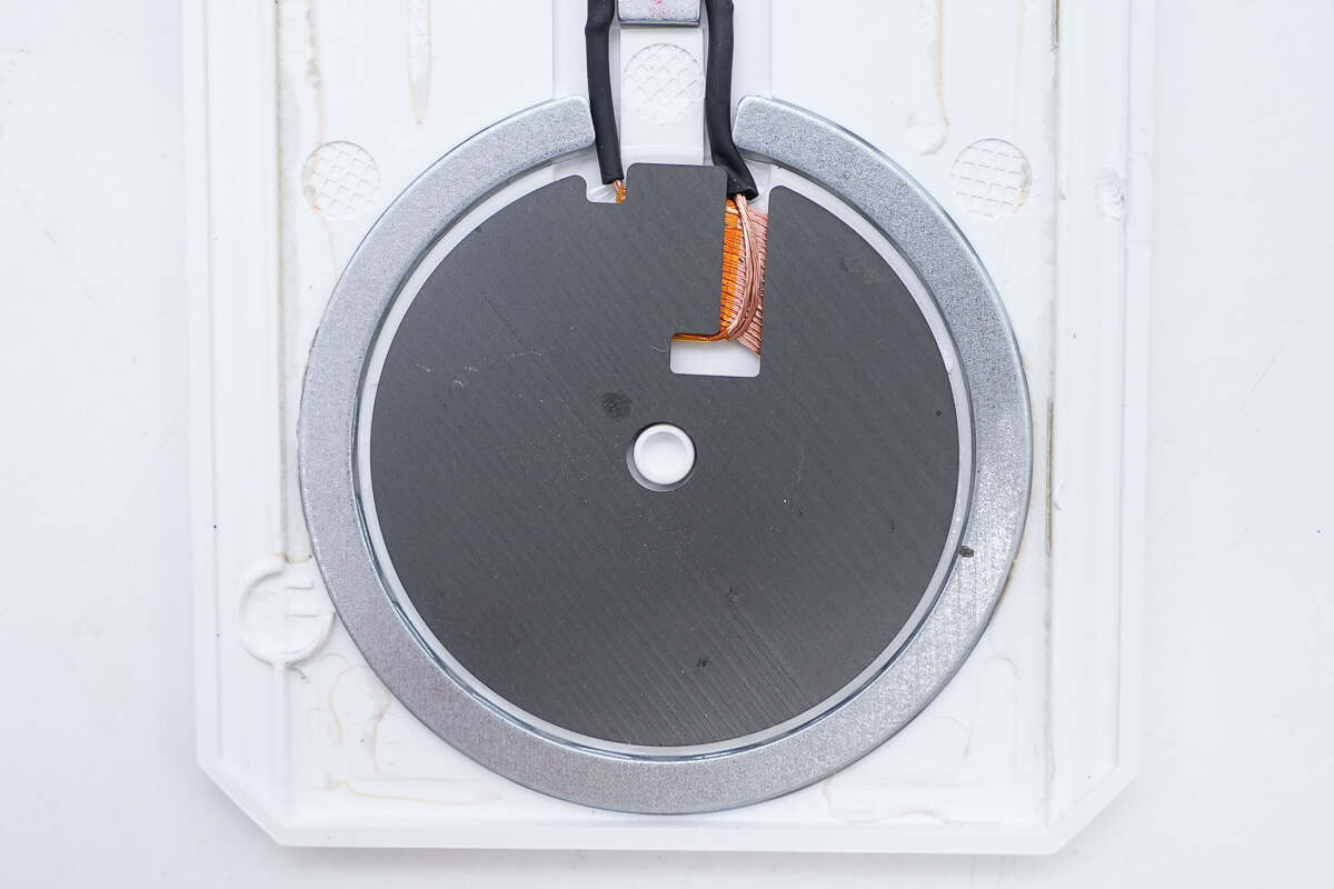
There is a black magnetic isolation sheet on the coil and a ring magnet on the edge for adsorbing the phone.
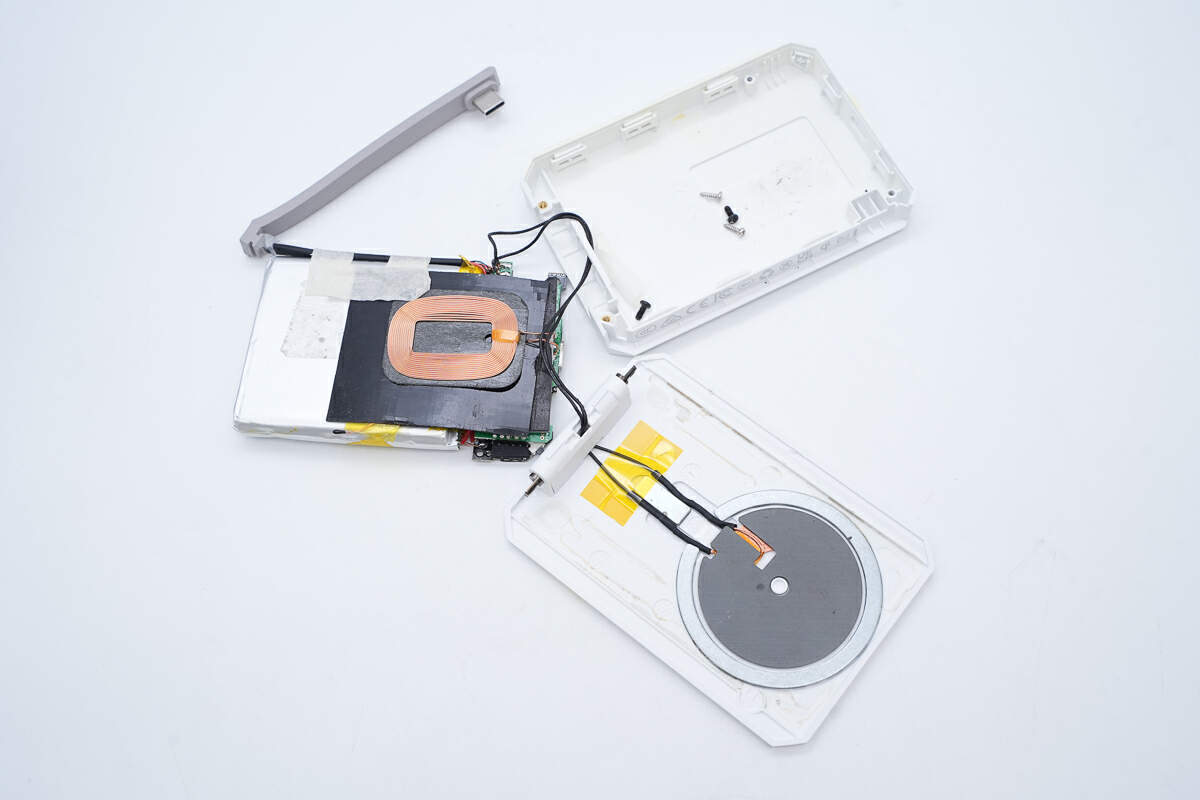
The wiring of the coil inside the flip cover is shown in the figure.
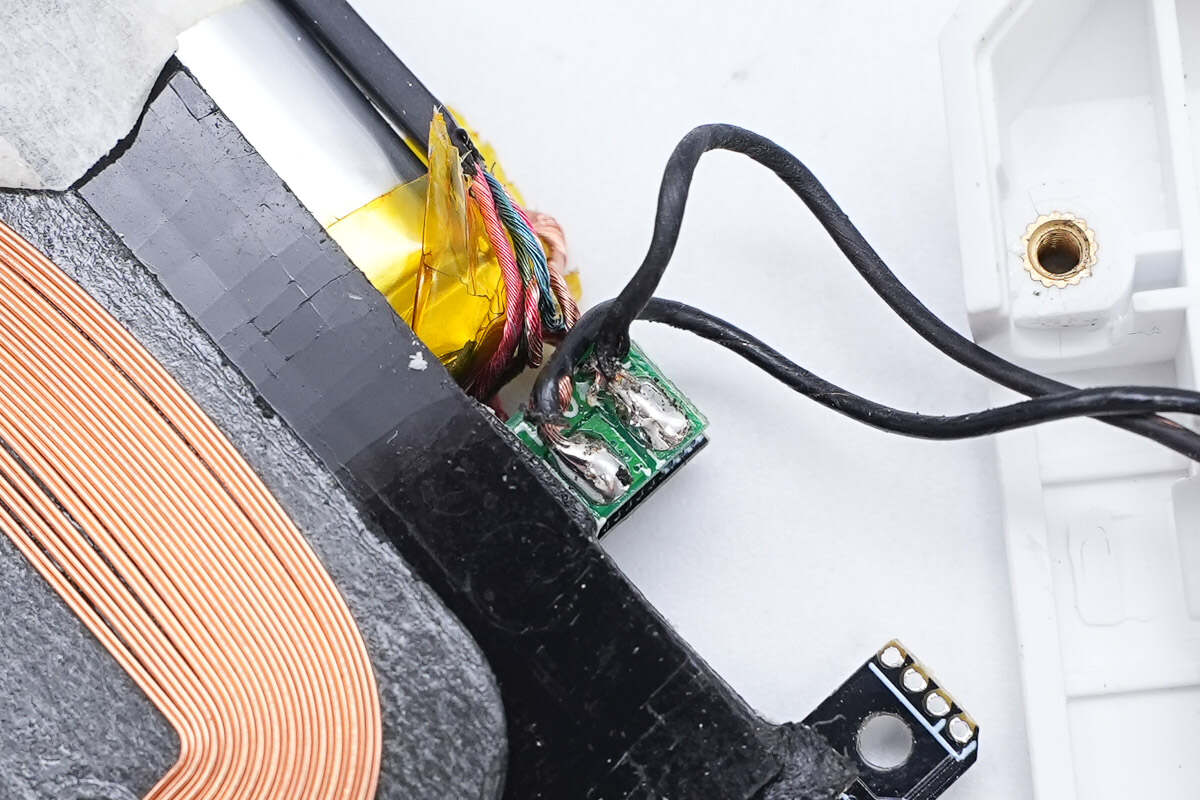
The coil inside the flip cover is connected to the PCBA module through wire welding.
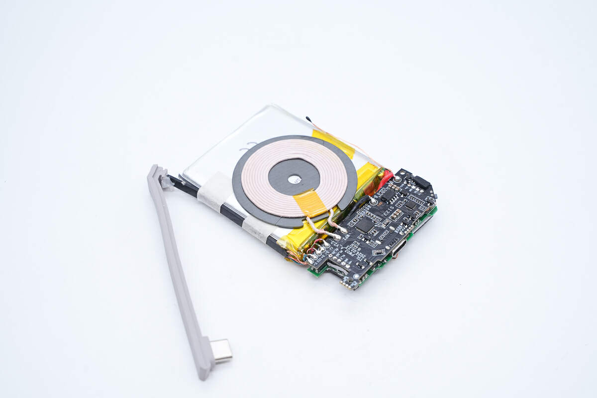
Let’s look at the PCBA module and battery pack.
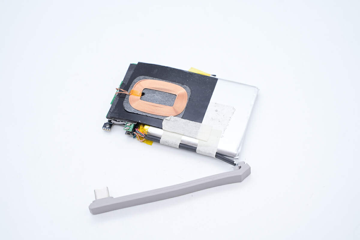
The wireless charging coil is attached to the back of the battery pack.
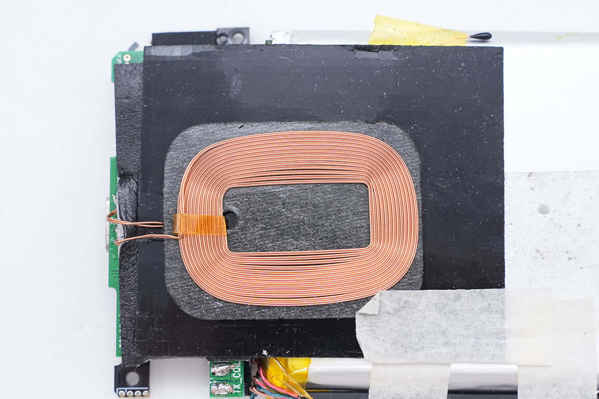
A magnetic isolation sheet is pasted between the wireless charging coil and the battery and fixed with double-sided tape.
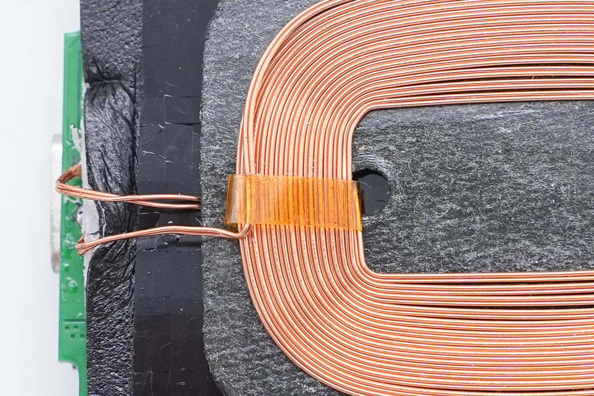
The coil is wound with magnet and insulated wires and tightened with high-temperature tape.
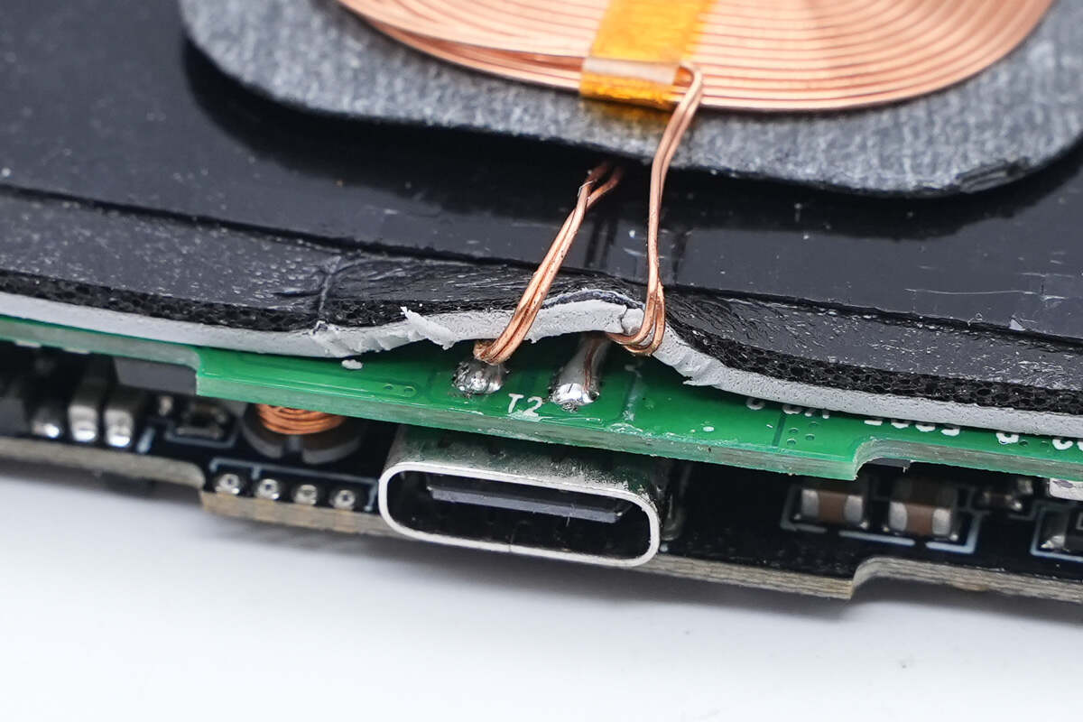
The wires of the coil are soldered to the PCBA module.
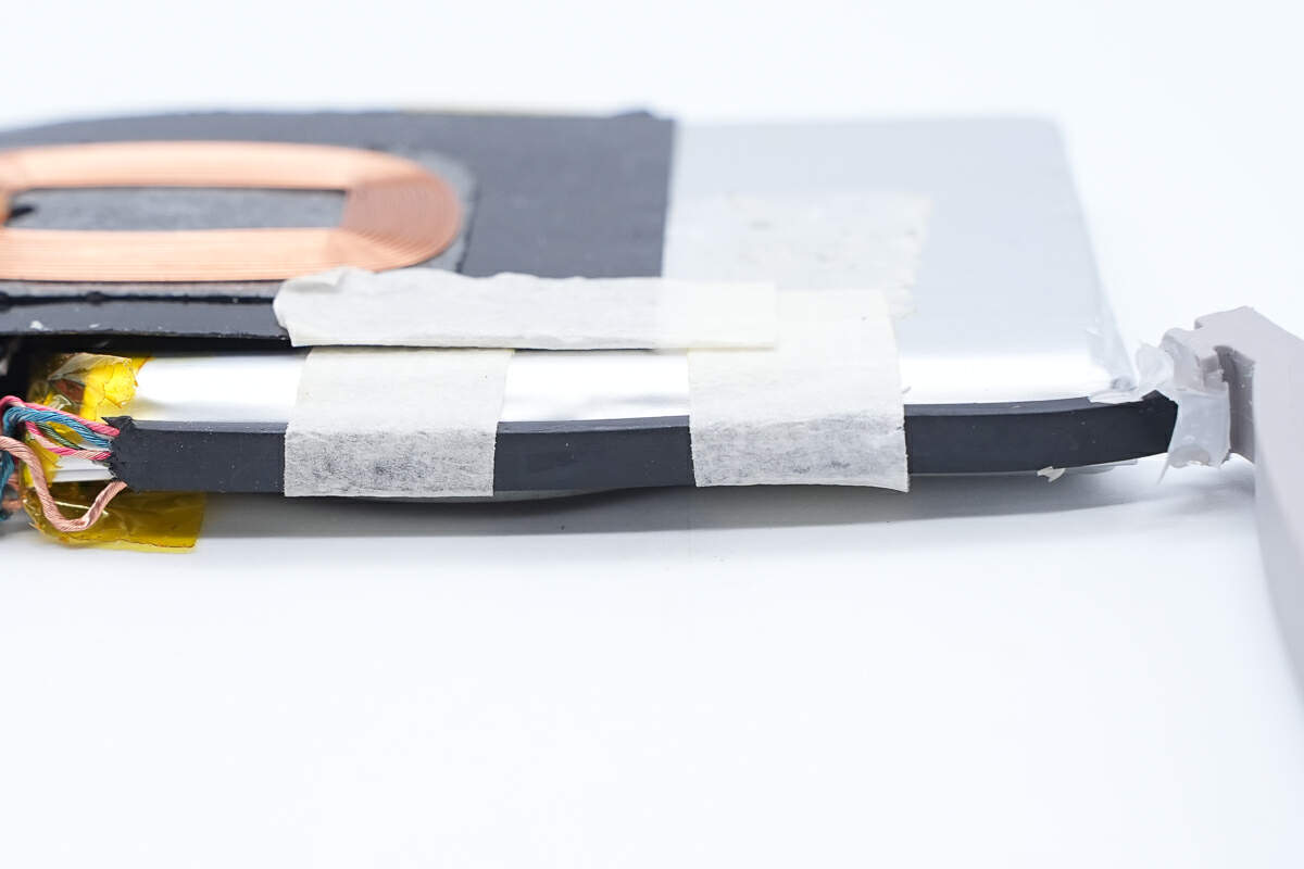
The wire cores of the integrated cable are wrapped with black rubber and adhered to the side of the battery.
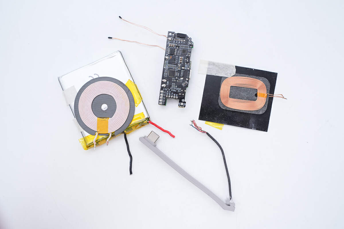
Disconnect the coil wires, battery pack, and PCBA module.
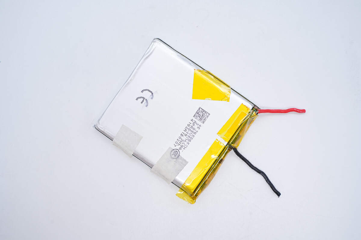
This is the battery.
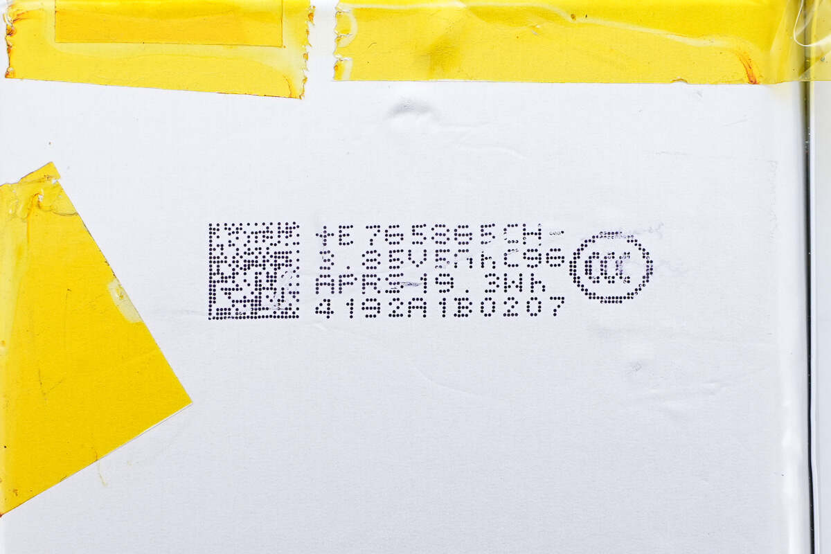
The 765865 battery is from APRS. The rated voltage is 3.85V, the capacity is 5Ah, and the energy is 19.3W.
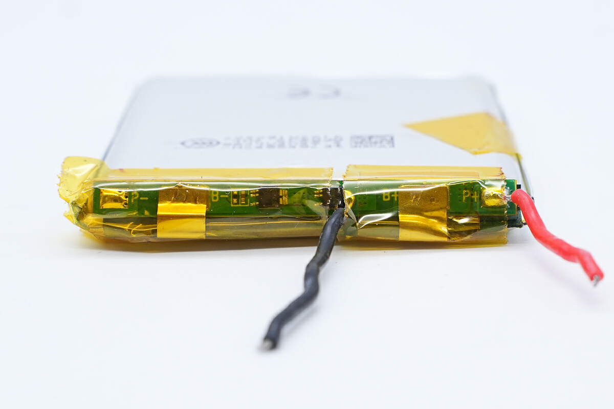
There is a battery protection PCB at the battery cell tabs.
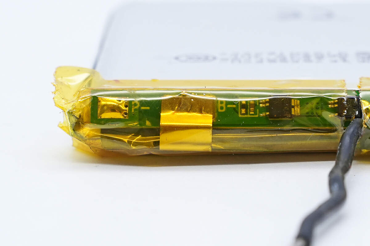
The battery protection PCB is connected by spot welding and insulated by high-temperature tape.
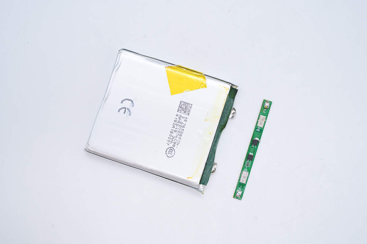
Remove the battery protection PCB.
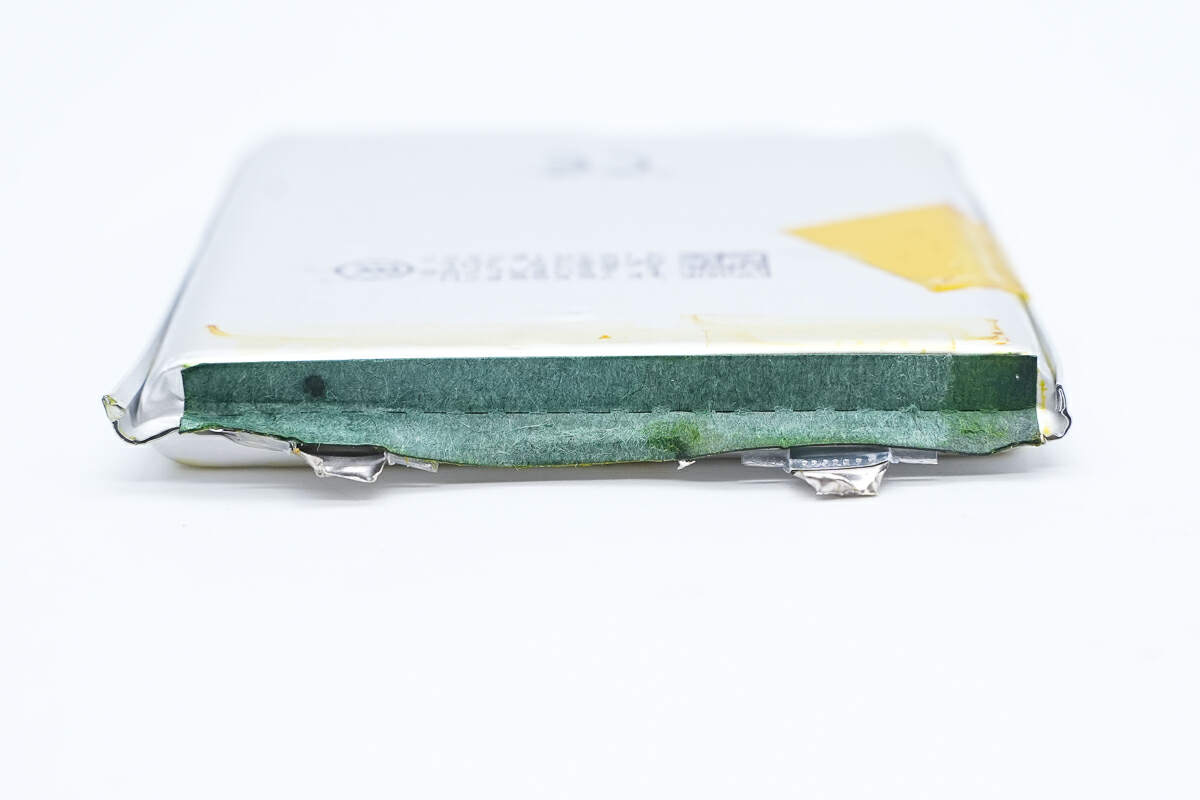
The battery cell and the battery protection PCB are insulated by barley paper.
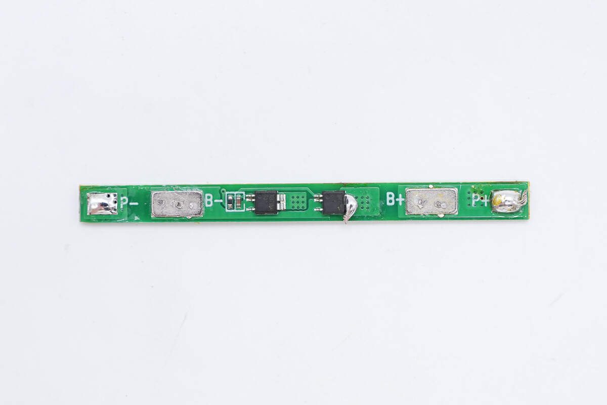
Two battery protection chips are on the battery protection PCB.
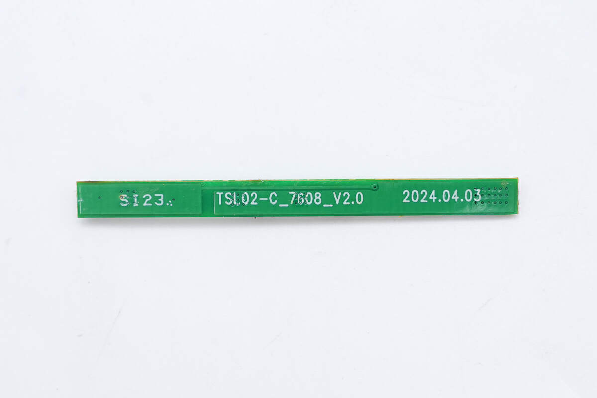
There are no components on the back.
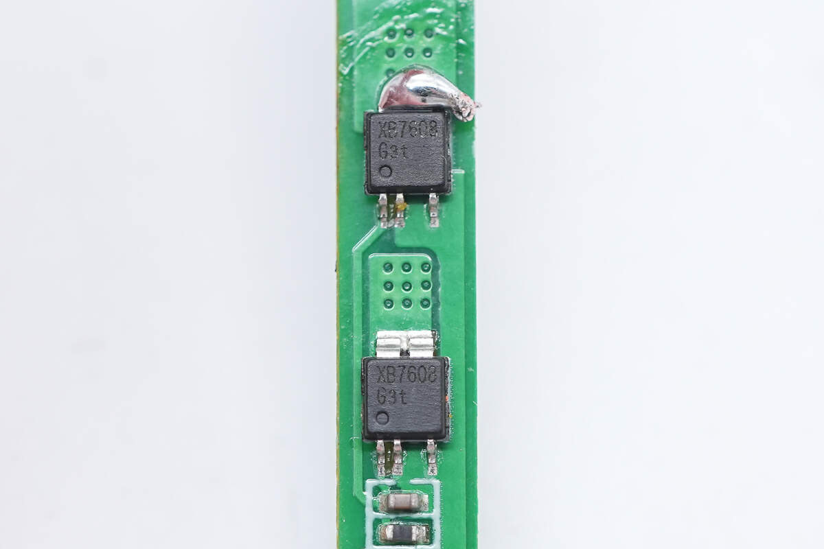
These are two battery-protection MOSFETs.
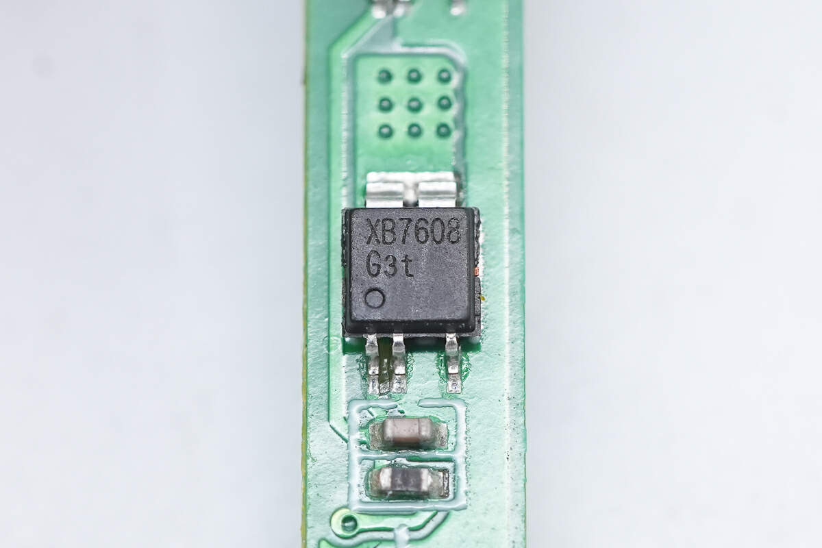
The MOSFET is from XySemi and adopts CPC5 package. Model is XB7608G.
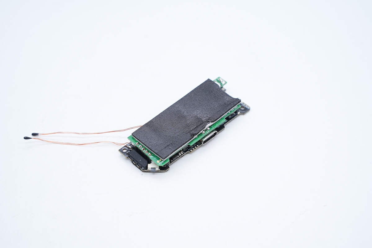
The PCBA module consists of two PCBs, a green one and a black one.
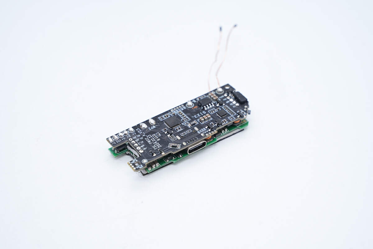
Two PCBAs are connected by pin headers.
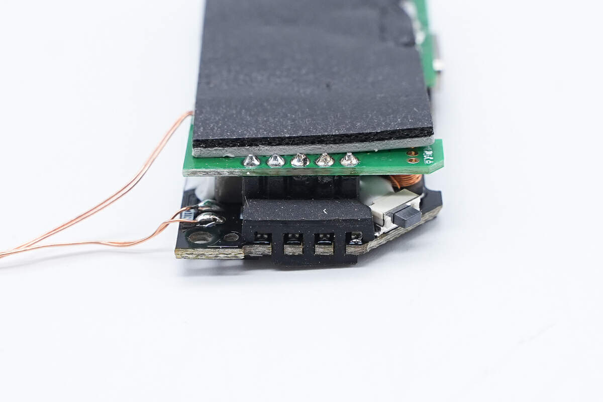
There is a gray thermal pad and a piece of black foam on top of the green PCBA.
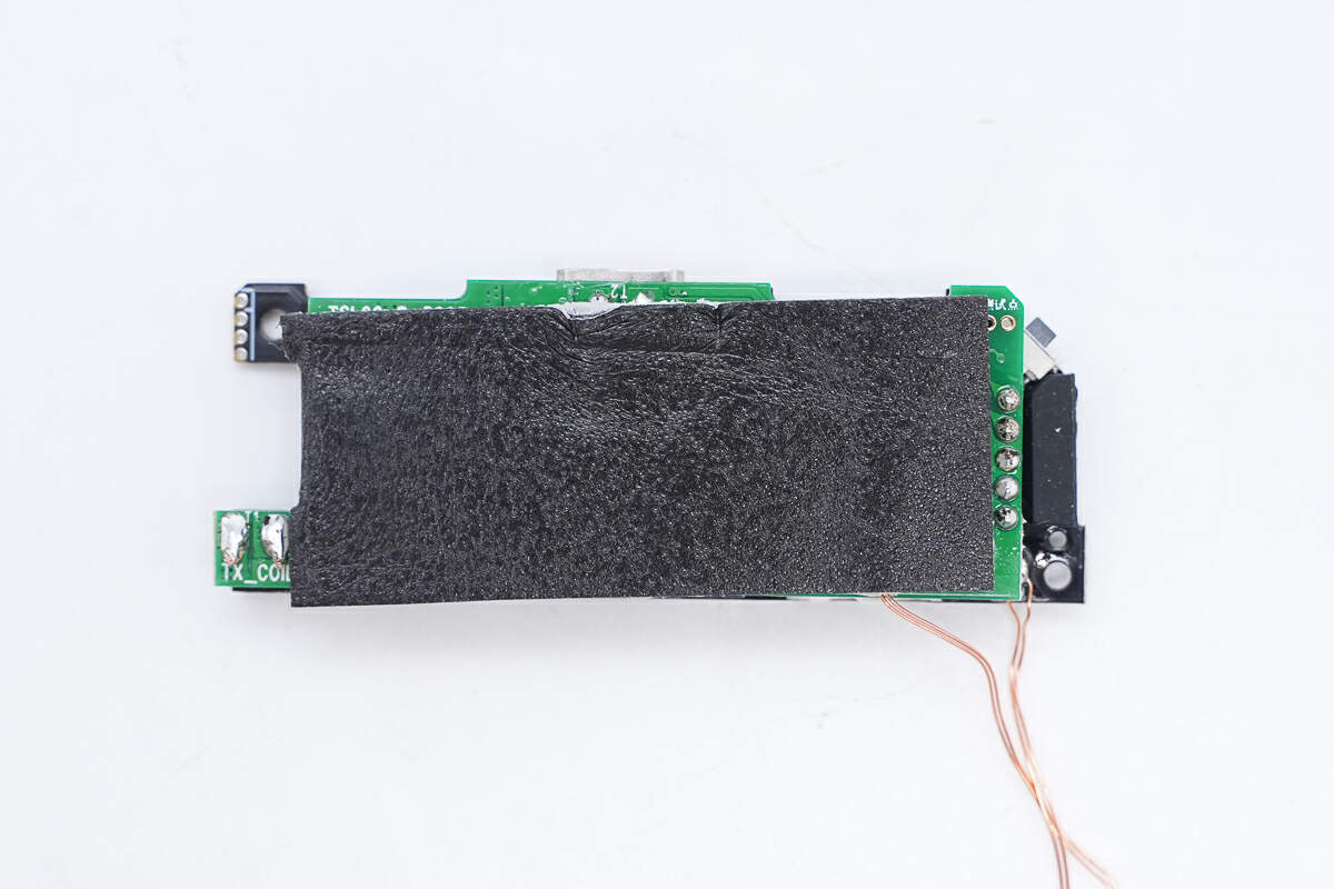
There is also a layer of silicone in the middle of the foam to enhance heat dissipation, and the foam provides buffering and protection for the PCB.
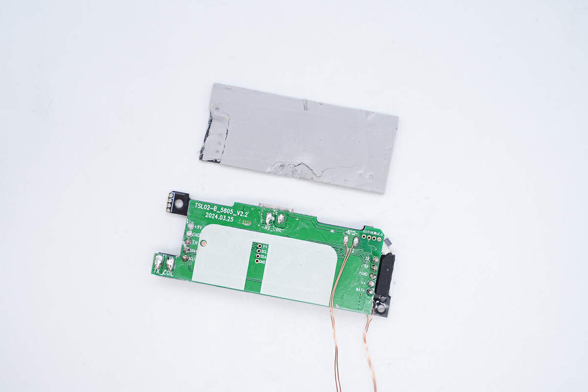
Remove the foam and thermal pad.
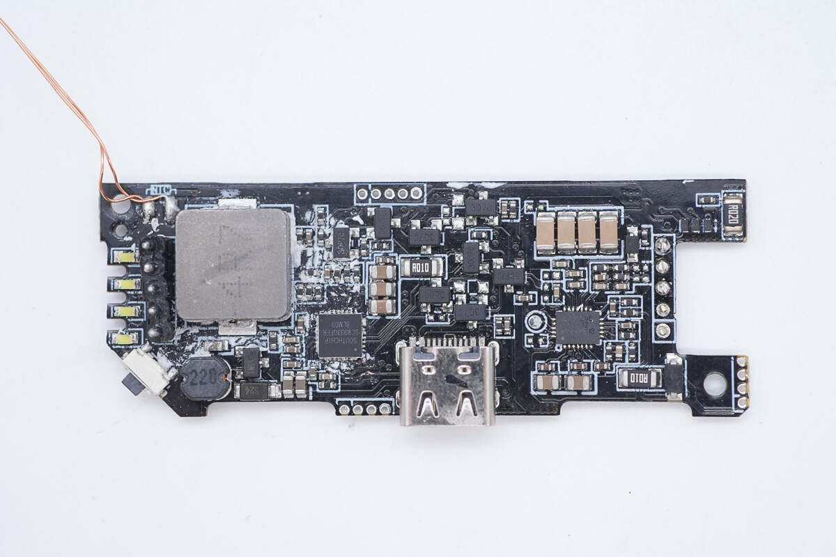
The front of the black PCB has four LED lamp beads, an alloy inductor, a master control chip, a USB-C socket, a resonant capacitor, and a wireless charging chip.
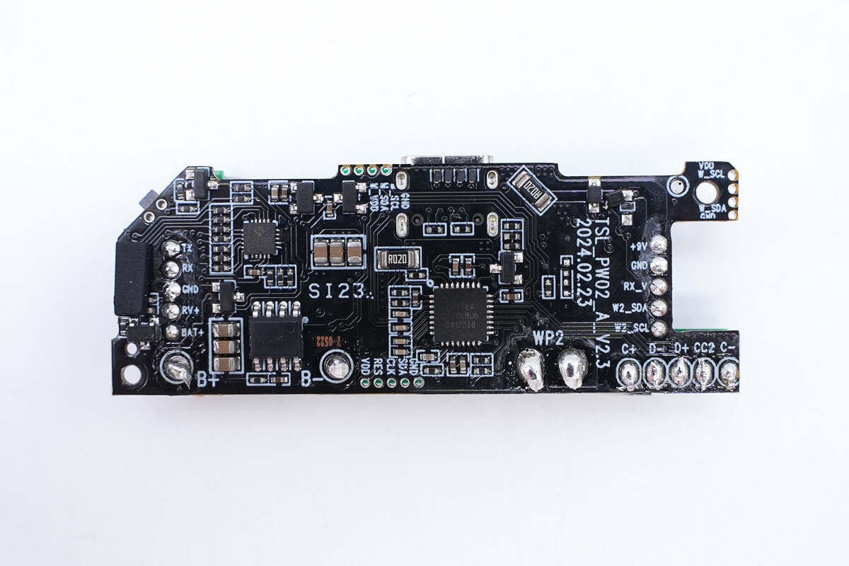
There is an MCU, a battery protection chip, and a protocol chip on the back.
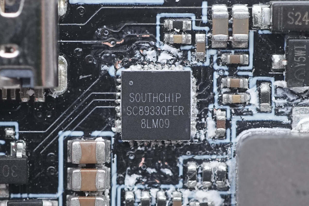
The master control chip is from SOUTHCHIP and adopts QFN32 package. It is a synchronous buck charging converter with reverse boost discharge function. The chip integrates two ultra-low resistance NMOS. Model is SC8933.
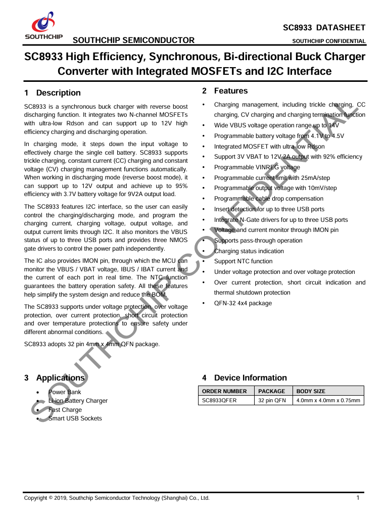
Here is the information about SOUTHCHIP SC8933.
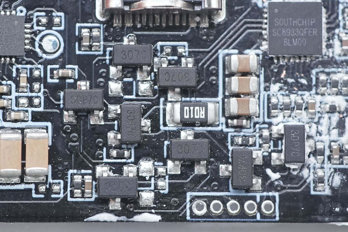
This is the VBUS MOSFET used to switch the USB-C port and USB-C cable.
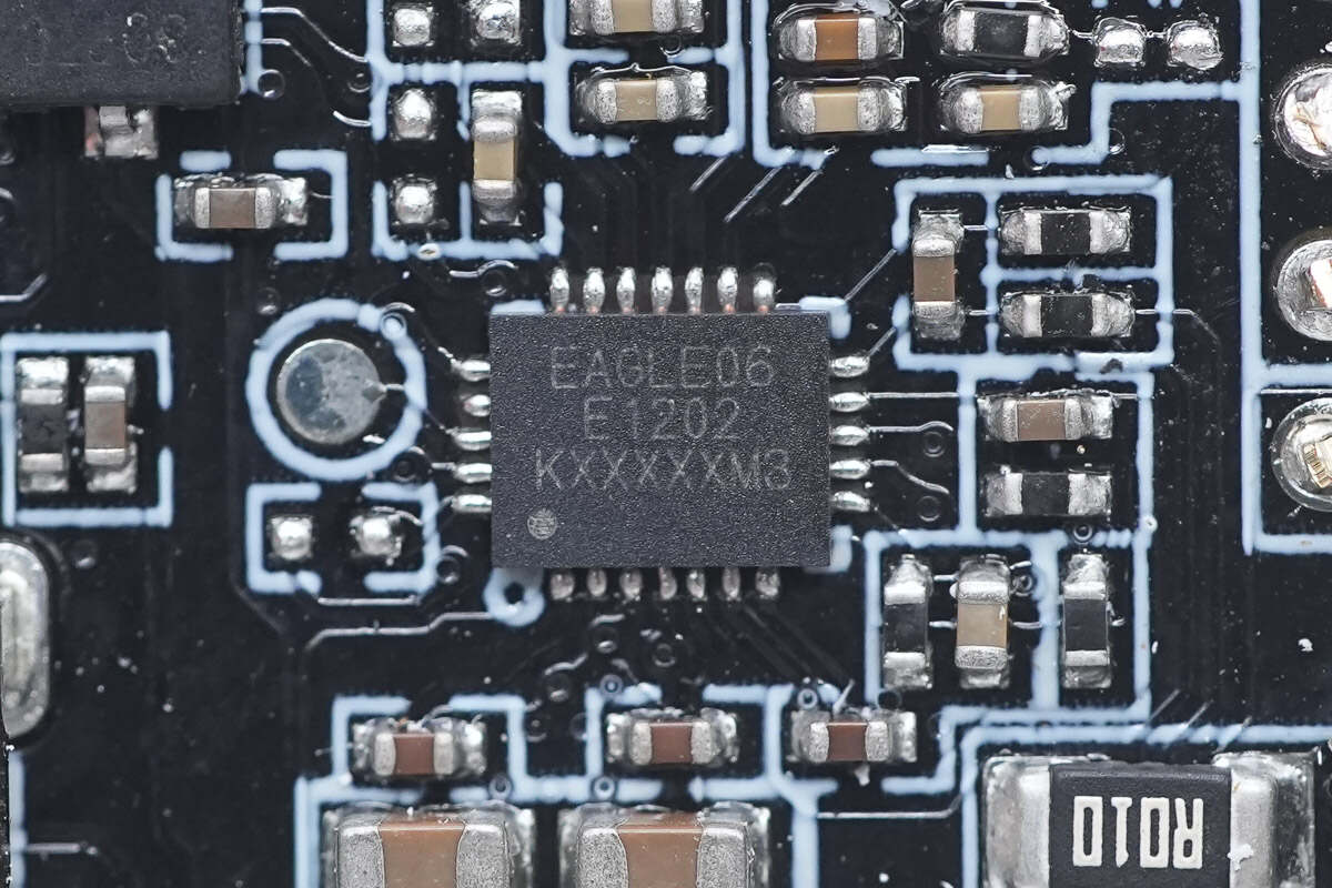
The wireless charging chip is from MAXiC and adopts FCQFN24L package. It is a highly integrated, high-performance wireless charging transmitter chip based on magnetic induction. It supports WPC Qi2 wireless charging protocol and multiple wired fast charging protocols such as PD, UFCS, FCP, SCP, QC, etc. It has passed PD and UFCS wired fast charging protocol certification and supports 4-20V wide input voltage and up to 15W output power.
It supports overvoltage protection (OVP), overcurrent protection (OCP), under-voltage protection (UVP), and overtemperature protection (OTP). In addition, the chip also embeds a dynamic power limit (DPL) comparator to prevent the IC from entering the UVLO state when the input power cannot meet the output power demand. If the VDD voltage drops below the DPL threshold, the chip will reduce the output power accordingly to protect the system from the UVLO state. Model is MT5806.
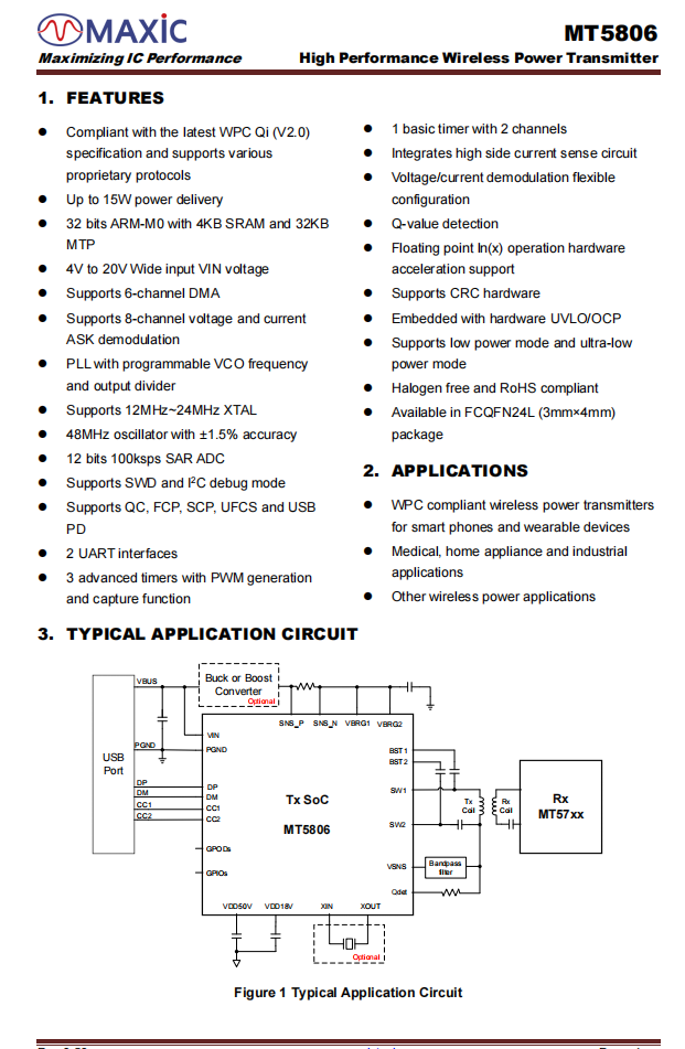
Here is the information about MAXiC MT5806.
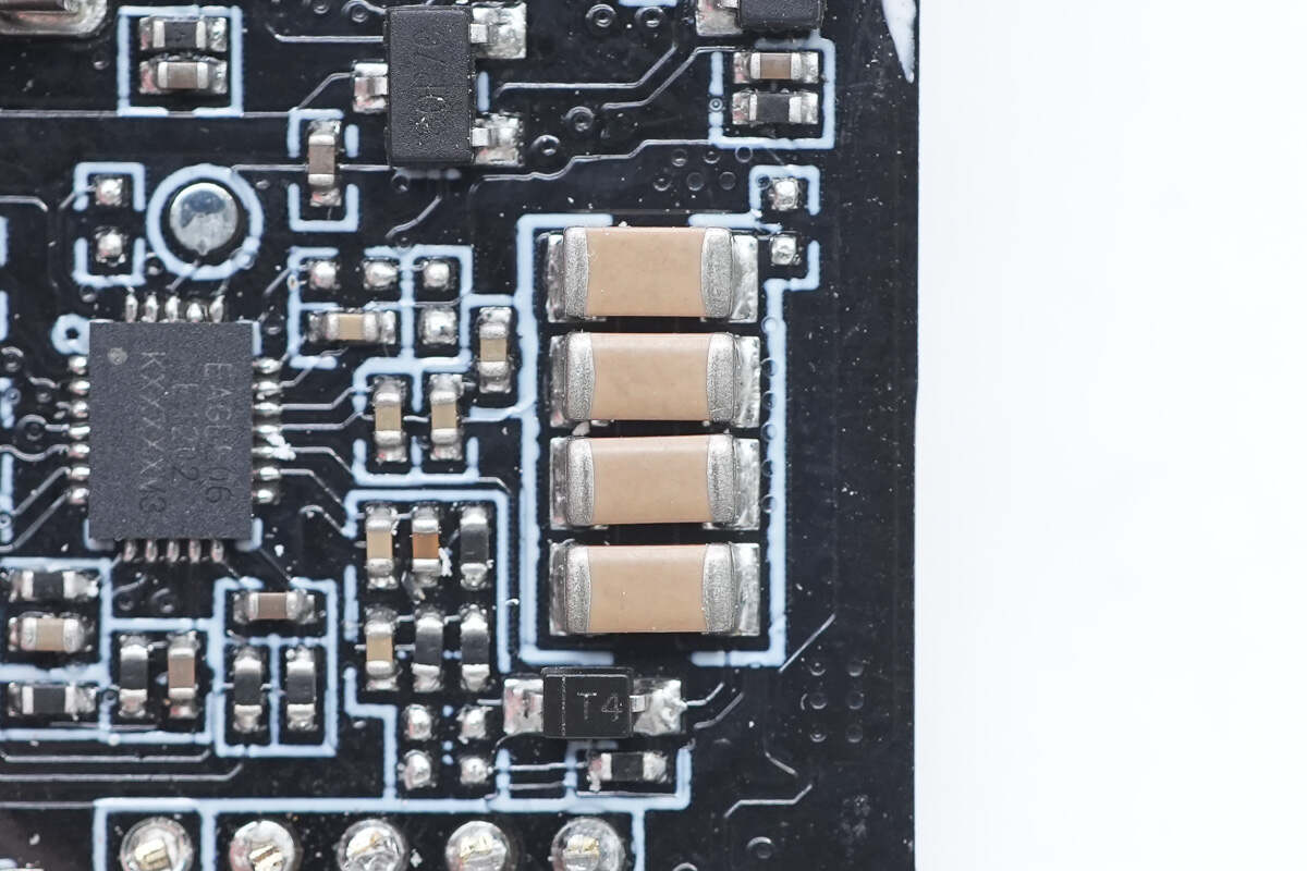
These are four resonant capacitors connected in parallel.
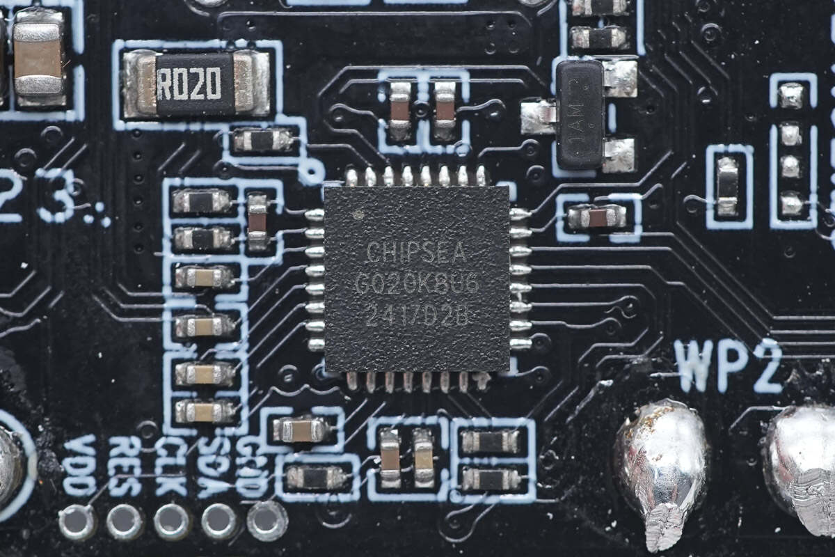
The USB-C protocol chip is from Chipsea and adopts QFN24 and QFN32 packages. It supports dual-channel independent USB-C port applications and has passed PD3.1 certification with good compatibility. Model is CS32G020K8U6.
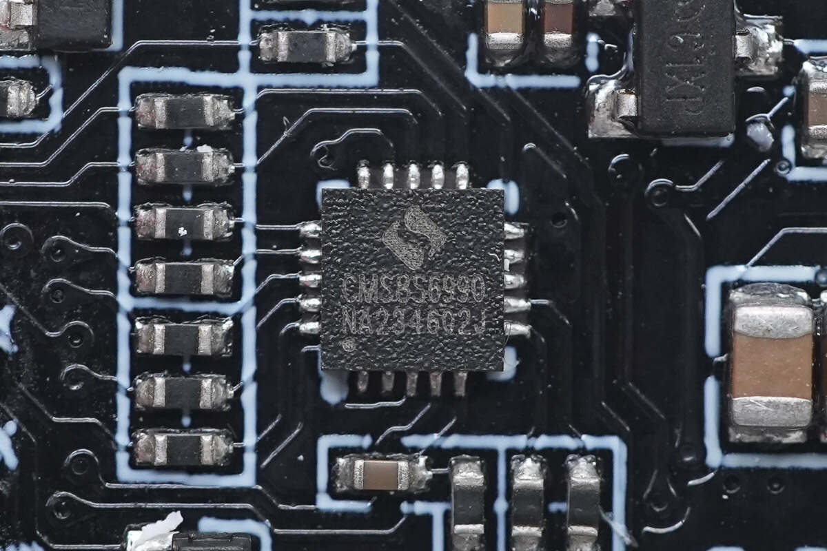
The wireless charging master control chip is from Cmsemicon. It is a general-purpose MCU, an enhanced 1T 8051, with built-in analog comparator, op-amp, and 6-channel PWM output for wireless charging control. Model is CMS8S6990.
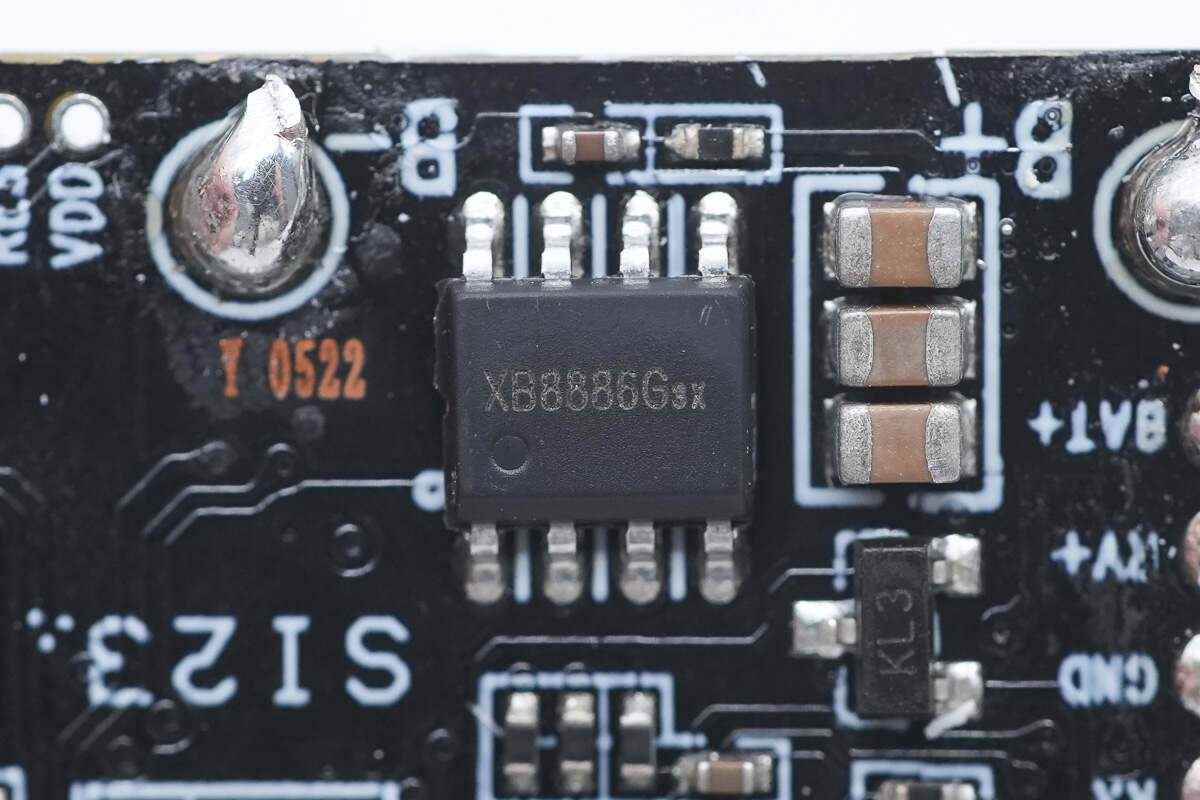
The battery protection chip is from Xysemi and adopts SOP8-PP package. It is a highly integrated lithium-ion/polymer battery protection solution. Model is XB8886G.
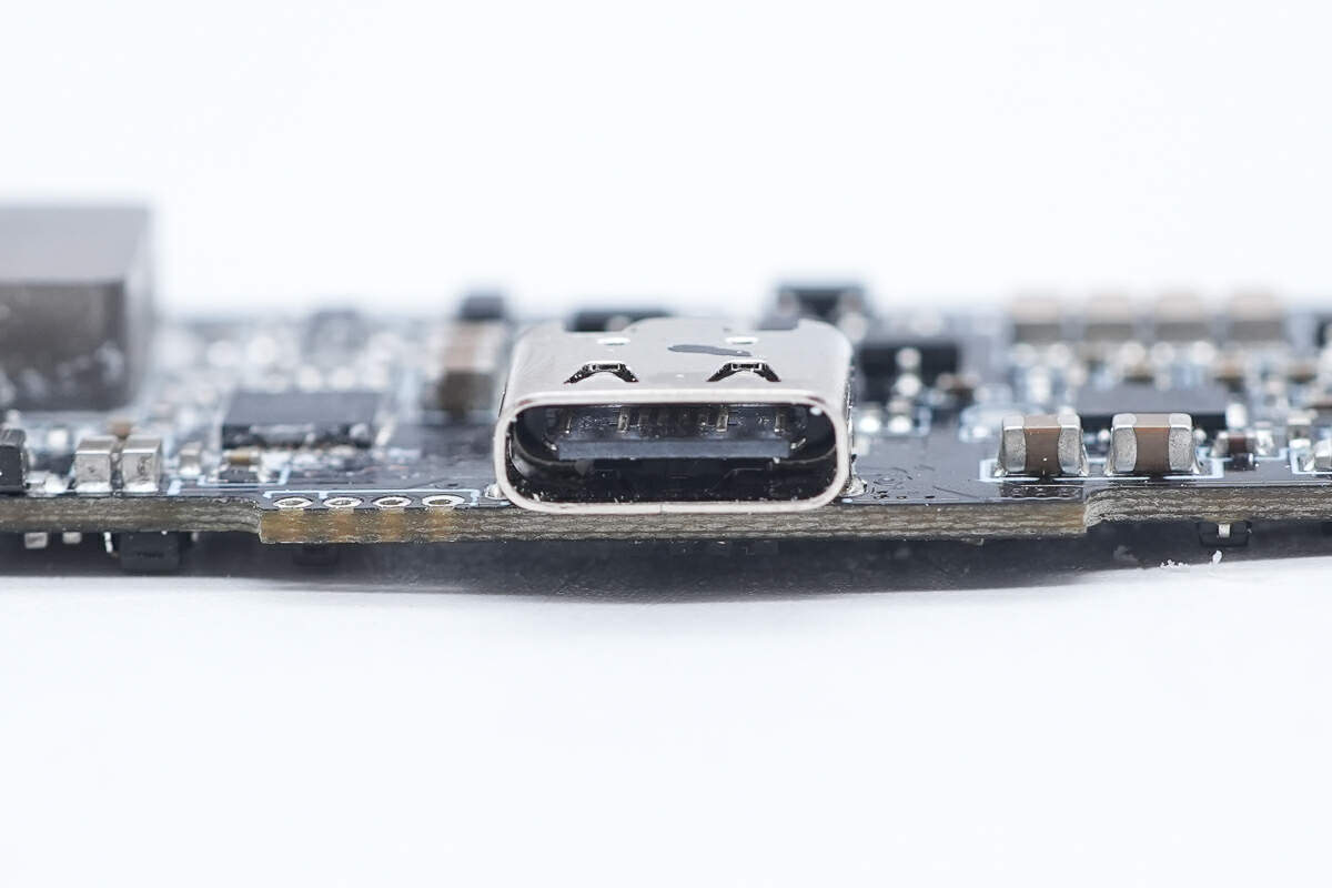
The plastic sheet of the USB-C port is black.
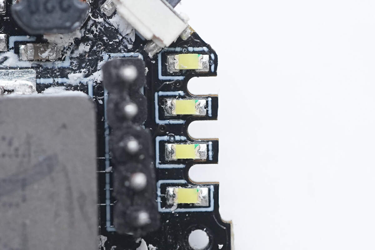
These are four LED lamp beads.
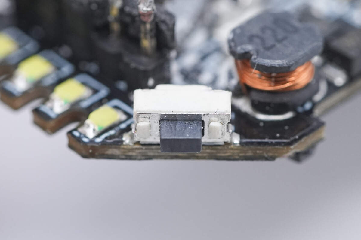
This is the power button.
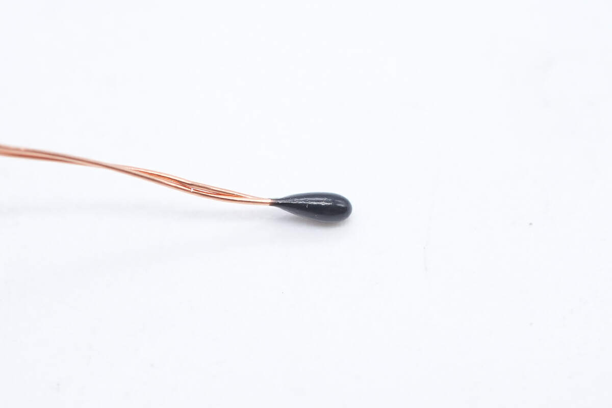
This is a thermistor used to detect the temperature of the coil and battery pack inside the case.
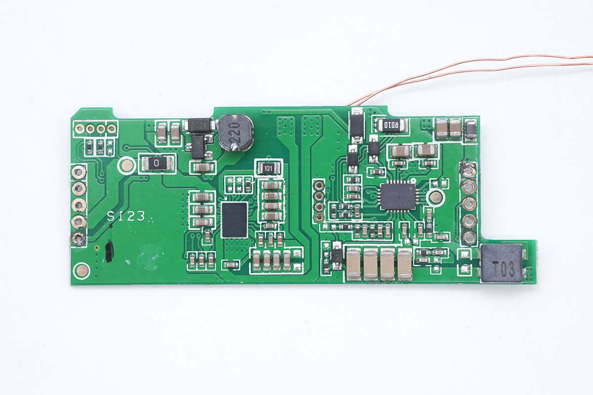
There is a wireless charging receiver chip, a wireless charging chip, four resonant capacitors, and a filter inductor on the front of the green PCBA.
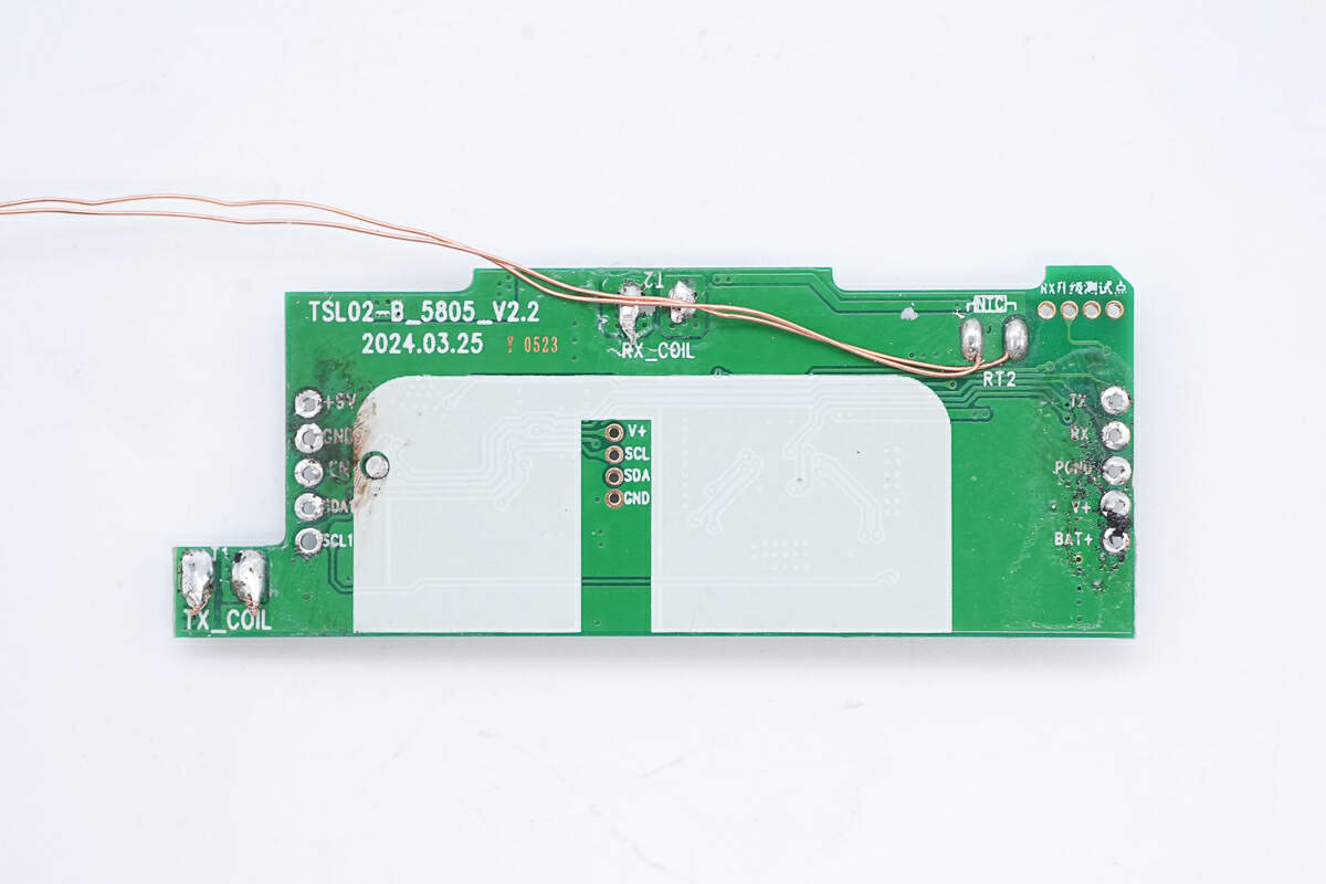
There is a thermistor on the back to detect the battery temperature.
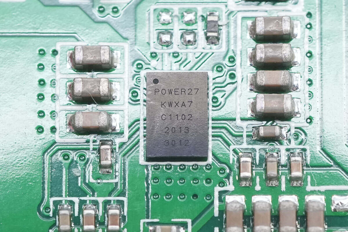
The wireless charging receiver chip marked with POWER27 is from MAXiC and adopts WLCSP52 package. It is a high-efficiency wireless charging receiver chip. It is a single-chip solution that supports 20W power and can be configured as a wireless transmitter to power other receivers. The chip complies with the WPC Qi 1.2.4 specification. It has a built-in ARM M0 processor, 8KB SRAM, and 16KB MTP memory. It has built-in overvoltage and overcurrent protection and supports the I2C interface and configurable GPIO interface. Model is MT5727H.
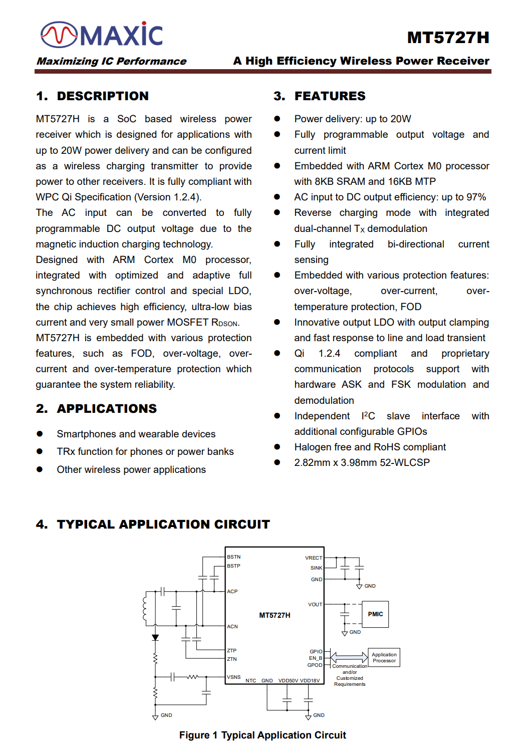
Here is the information about MAXiC MT5727H.
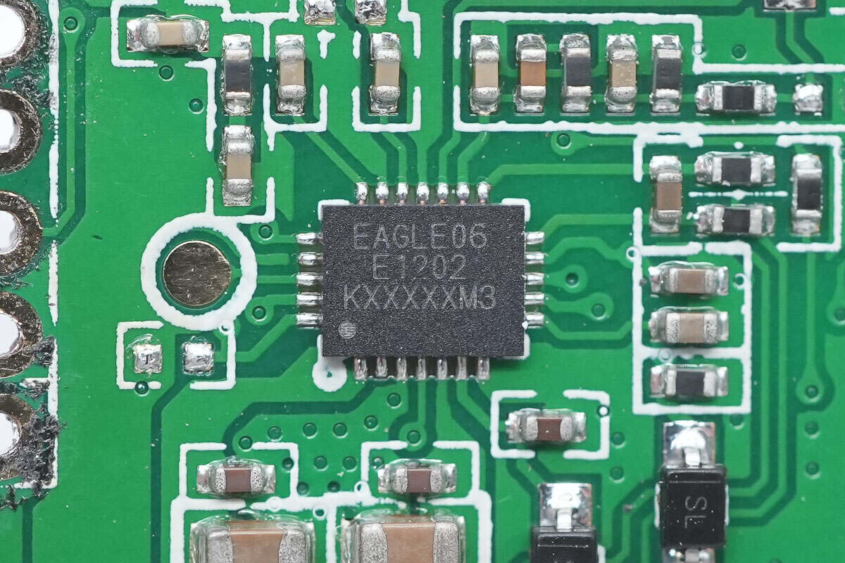
This wireless charging chip also comes from MAXiC and has the same model as the previous one.
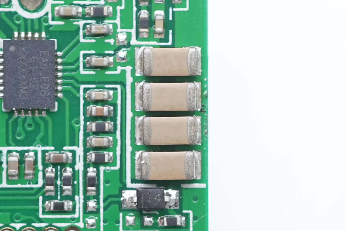
These are four resonant capacitors connected in parallel.
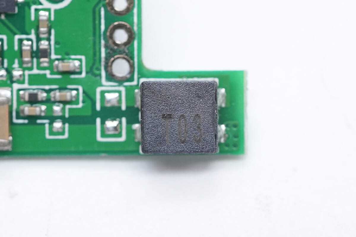
The filter inductor is marked with T03.
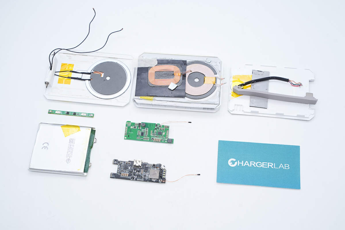
Well, those are all components of the Tesla Wireless Portable Charger.
Summary of ChargerLAB
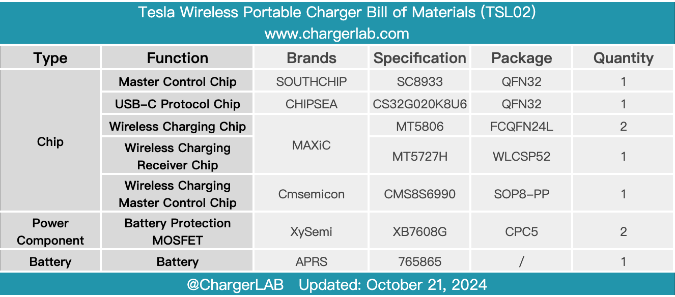
Here is the component list of the Tesla Wireless Portable Charger for your convenience.
It has two wireless charging output panels that support 15W and 5W, respectively, and a 10W wireless charging input panel. In addition, it is also equipped with a USB-C port and a USB-C cable that supports a maximum of 20W input and output.
After taking it apart, we found it adopts a 5000mAh battery cell from APRS and XySemi's integrated battery protection chip for battery pack protection. The PCBA module consists of two PCBs. Two thermistors are inside to detect the coil and battery temperatures, respectively. The PCBA module uses a thermal pad and foam to enhance heat dissipation. The heat dissipation and buffer protection are excellent, and the workmanship is solid.
Related Articles:
1. Review of Tesla Wireless Portable Charger
2. Foldable Design, Dual Wireless Charging | Review of Tesla Wireless Portable Charger
3. Immersive Unboxing of Tesla Wireless Portable Charger

